TOYOTA 1HZ 1HD t 1990 REPAIR MANUAL HƯỚNG dẫn sửa CHỮA ĐỘNG cơ 1HZ 1HD t TOYOTA
Bạn đang xem bản rút gọn của tài liệu. Xem và tải ngay bản đầy đủ của tài liệu tại đây (33.42 MB, 348 trang )
FOREWORD
This repair manual has been prepared to provide information
covering general service repairs for the 1 PZ, 1 HZ and 1HD-T
engines equipped on the TOYOTA LAND CRUISER and
COASTER.
Applicable models:
PZJ70, 73, 75 series
HZJ70, 73, 75, 80 series
HDJ80 series
HZB30 series
HDB30 series
Please note that the publications below have also been prepared
as relevant service manuals for the components and system in
this engine.
All information in this manual is based on the latest product
information at the time of publication. However, specifications
and procedures are subject to change without notice.
TOYOTA MOTOR CORPORATION
Manual Name
Land Cruiser (Wagon) New Car Features
Pub. No.
NCF064E
CAUTION
This manual does not include all the necessary items about repair and service, this manual is made
for the purpose of the use for the persons who have special techniques and certifications. In the
cases that non-specialized or uncertified technicians perform repair or service only using this manu-
al or without proper equipment or tool, that may cause severe injury to you or other people around
and also cause damage to your customer's vehicle.
In order to prevent dangerous operation and damages to your customer's vehicle, be sure to follow
the instruction shown below.
Must read this manual thoroughly. It is especially important to have good understanding all the
contents written in the PRECAUTION of "IN" section.
The service method written in this manual is very effective to perform repair and service. When
performing the operations following the procedures using this manual, be sure to use tools spe-
cified and recommended. If using non-specified or recommended tools and service method,
be sure to confirm safety of the technicians and any possibility of causing personal injury or
damage to the customer's vehicle before starting the operation.
If part replacement is necessary, must replace the part with the same part number or equivalent
part. Do not replace it with inferior quality.
It is important to note that this manual contains various "Cautions" and "Notices" that must be
carefully observed in order to reduce the risk of personal injury during service or repair, or the
possibility that improper service or repair may damage the vehicle or render it unsafe. It is also
important to understand that these "Cautions" and "Notices" are not exhaustive, because it is
important to warn of all the possible hazardous consequences that might result from failure to
follow these instructions.
TOYOTA
1PZ, 1HZ, 1HD-T ENGINE
REPAIR MANUAL
INTRODUCTION
ENGINE MECHANICAL
TURBOCHARGER SYSTEM
FUEL SYSTEM
COOLING SYSTEM
LUBRICATION SYSTEM
STARTING SYSTEM
CHARGING SYSTEM
SERVICE SPECIFICATIONS
STANDARD BOLT TORQUE SPECIFICATIONS
SSTANDSSM
©2001 TOYOTA MOTOR CORPORATION
All rights reserved. This book may not be repro-
duced or copied, in whole or in part, without the
written permission of Toyota Motor Corporation.
First Printing: Feb. 8,1990 01-900208-00
34th Printing: Aug. 28,2001 34-010828-06-2
IN-1
INTRODUCTION
Page
HOW TO USE THIS MANUAL IN-2
IDENTIFICATION INFORMATION IN-4
GENERAL REPAIR INSTRUCTIONS IN-4
ABBREVIATIONS USED IN THIS MANUAL IN-7
IIM-2
INTRODUCTION How to Use This Manual
HOW TO USE THIS MANUAL
To assist you in finding your way through this manual, the
Section Title and major heading are given at the top of every
page.
An INDEX is provided on the 1st page of each section to guide
you to the item to be repaired.
At the beginning of each section, PRECAUTIONS are given that
pertain to all repair operations contained in that section.
Read these precautions before starting any repair task.
TROUBLESHOOTING tables are included for each system to
help you diagnose the problem and find the cause. The repair for
each possible cause is referenced in the remedy column to
quickly lead you to the solution.
REPAIR PROCEDURES
Most repair operations begin with an overview illustration. It
identifies the components and shows how the parts fit together.
Example:
IN-3
INTRODUCTION - How to Use This Manual
The procedures are presented in a step-by-step format:
• The illustration shows what to do and whereto do it.
• The task heading tells what to do.
• The detailed text tells how to perform the task and gives other
information such as specifications and warnings.
Example:
This format provides the experienced technician with a
FAST TRACK to the information needed. The upper case
task heading can be read at a glance when necessary, and
the text below it provides detailed information. Important
specifications and warnings always stand out in bold type.
REFERENCES
References have been kept to a minimum. However, when they
are required, you are given the page to refer to.
SPECIFICATIONS
Specifications are presented in bold type throughout the text
where needed. You never have to leave the procedure to look up
your specifications. They are also found in Appendix A for quick
reference.
CAUTIONS, NOTICES, HINTS:
• CAUTIONS are presented in bold type, and indicate there is a
possibility of injury to you or other people.
• NOTICES are also presented in bold type, and indicate the
possibility of damage to the components being repaired.
• HINTS are separated from the text but do not appear in bold.
They provide additional information to help you efficiently
perform the repair.
IIM-4
INTRODUCTION - Identification Information, General Repair Instructions
IDENTIFICATION INFORMATION
ENGINE SERIAL NUMBER
The engine serial number is stamped on the left side of the
cylinder block.
GENERAL REPAIR INSTRUCTIONS
1. Use fender, seat and floor covers to keep the vehicle clean
and prevent damage.
2. During disassembly, keep parts in order to facilitate reas-
sembly.
3. Observe the following:
(a) Before performing electrical work, disconnect the
negative ( —) cable from the battery terminal.
(b) If it is necessary to disconnect the battery for inspec-
tion or repair, always disconnect the cable from the
negative ( —) terminal which is grounded to the vehi-
cle body.
(c) To prevent damage to the battery terminal post, loosen
the terminal nut and raise the cable straight up with-
out twisting or prying it.
(d) Clean the battery terminal posts and cable terminals
with a shop rag. Do not scrape them with a file or
other abrasive object.
(e) Install the cable terminal to the battery post with the
nut loose, and tighten the nut after installation. Do not
use a hammer to tap the terminal onto the post.
(f) Be sure the cover for the positive ( + ) terminal is
properly in place.
4. Check hose and wiring connectors to make sure that they
are secure and correct.
5. Non-reusable parts
(a) Always replace cotter pins gaskets, O-rings, oil seals,
etc. with new ones.
(b) Non-reusable parts are indicated in the component
illustrations by the "•" symbol.
6. Precoated Parts
Precoated parts are bolts and nuts, etc. that are coated with
a seal lock adhesive at the factory.
(a) If a precoated part is retightened, loosened or caused
to move in any way, it must be recoated with the
specified adhesive.
IN-5
INTRODUCTION - General Repair Instructions
(b) Recoating of Precoated Parts
(1) Clean off the old adhesive from the part's
threads.
(2) Dry with compressed air.
(3) Apply the specified seal lock adhesive to the
part's threads.
(c) Precoated parts are indicated in the component illus-
trations by the "*" symbol.
7. When necessary, use a sealer on gaskets to prevent leaks.
8. Carefully observe all specifications for bolt torques. Always
use a torque wrench.
9. Use of special service tools (SST) and special service
materials (SSM) may be required, depending on the nature
of the repair. Be sure to use SST and SSM where specified
and follow the proper work procedure. A list of SST and
SSM can be found at the back of this manual.
10. When replacing fuses, be sure the new fuse is the correct
amperage. DO NOT exceed the rating or use one of a lower
rating.
11. Care must be taken when jacking up and supporting the
vehicle. Be sure to lift and support the vehicle at the proper
locations.
(a) If the vehicle is to be jacked up only at the front or rear
end, be sure to block the wheels in order to ensure
safety.
(b) After the vehicle is jacked up, be sure to support it on
stands. It is extremely dangerous to do any work on
the vehicle raised on a jack alone, even for a small job
that can be finished quickly.
12. Observe the following precautions to avoid damaging the
parts:
(a) Be careful not to drop electrical components, such as
sensors or relays. If they are dropped on a hard floor,
they should be replaced and not reused.
(b) To pull apart electrical connectors, pull on the con-
nector itself, not the wires.
(c) To disconnect vacuum hoses, pull on the end, not the
middle of the hose.
IIM-6
INTRODUCTION General Repair Instructions
(d) When steam cleaning an engine, protect the air filter,
and injection pump from water.
(e) Never use an impact wrench to remove or install temp,
switches or temp, sensors.
(f) When checking continuity at the wire connector,
insert the tester probe carefully to prevent terminals
from bending.
(g) When using a vacuum gauge, never force the hose
onto a connector that is too large. Use a step-down
adapter instead. Once the hose has been stretched, it
may leak.
13. After removing and reinstalling the injection pump and fuel
hoses, clean off the fuel on engine components. In partic-
ular, be sure to check the radiator hose and by-pass hose,
because they deteriorate easily if they come into contact
with fuel.
IN-7
INTRODUCTION - Abbreviations Used in This Manual
ABBREVIATIONS USED IN THIS MANUAL
A/C Air Conditioner
ACV Air Control Valve
ACSD Automatic Cold Start Device
Approx. Approximately
A/T Automatic Transmission
BACS Boost and Altitude Compensation Stopper
BDC Bottom Dead Center
Ex. Except
FL Fusible Link
FIPG Formed in Place Gasket
HAC High Altitude Compensator
LH Left-Hand
LHD Left-Hand Drive
LST Load Sensing Timer
MP Multipurpose
M/T Manual Transmission
OHC Over Head Cam
O/S Oversized
PCS Power Control System
PCV Positive Crankcase Ventilation
RH Right-Hand
RHD Right-Hand Drive
SSM Special Service Materials
SST Special Service Tools
STD Standard
SW Switch
TDC Top Dead Center
U/S Undersize
w/ With
w/o Without
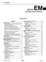
EM-1
ENGINE MECHANICAL
DESCRIPTION EM-2
TROUBLESHOOTING EM-4
Diesel Engine Diagnosis EM-4
Diesel Electrical System Diagnosis EM -14
ENGINETUNE-UP EM-17
COMPRESSION CHECK EM-30
TIMING BELT EM-32
TIMINGGEARS EM-42
CYLINDER HEAD EM-54
CYLINDER BLOCK EM-84
Page
EM-2
ENGINE MECHANICAL - Description
DESCRIPTION
The 1 PZ engine is an in-line 5-cylinder 3.5 liter OHC engine.
The 1 HZ and 1 HD-T engines are an in-line 6-cylinder 4.2 liter OHC engine.
1PZ
1HZ
1HD-T
EM8795 EM8792
EM8965 EM8793
EM8966 EM8794
EM-3
ENGINE MECHANICAL Description
The 1 PZ engine is an in-line 5-cylinder engine
with the cylinders numbered 1 -2-3-4-5 from
the front. This engine's injection order is
1-2-4-5-3.
The 1 HZ and 1HD-T engines are an in-line
6-cylinder engine with the cylinders numbered
1 -2-3-4-5-6 from the front. This engine's
injection order is 1 -4-2-6-3-5.
The crankshaft is supported by 6 (1 PZ) or 7 (1 HZ
and 1HD-T) bearings on the inside of the crank-
case. These bearings are made of aluminum alloy.
The crankshaft is integrated with 10 weights (1 PZ)
or 12 weights (1 HZ and 1HD-T) which are cast
along with it for balancing. Oil holes are built into
the crankshaft for supplying oil to the connecting
rods, bearings and other components.
The crankshaft bearing cap is of ladder frame
construction and is incorporated into the crank
case.
The cylinder head is made of cast iron with a
cross flow type intake and exhaust layout. The
combustion chambers are swirl chamber type for
the 1 PZ and 1 HZ engines and direct injection type
for the 1 H D-T engine. The camshaft journal part of
the cylinder head has camshaft caps made of alu-
minum alloy and is made of cast iron on the cylinder
head side. The camshaft journal has no bearings
(with the exception of the No.1 journal).
The 1 HZ and 1 HD-T engines has dual-type ex-
haust manifolds.
Exhaust and intake valves are equipped with
irregular pitch springs which are capable of follow-
ing the valves even at high engine speeds.
The camshaft is driven by the timing belt. The
camshaft journal is supported at 6 places (1 PZ) or
7 places (1 HZ and 1HD-T). Lubrication of the
camshaft journal and cam is accomplished by oil
being supplied through the oiler port in the No.6
(1 PZ) or No.7 (1 HZ and 1 HD-T) of the camshaft
journal.
Adjustment of the valve clearance is done by
means of an outer shim type system, in which valve
adjusting shims are located above the valve lifters.
This permits replacement of the shims without
removal of the camshaft.
Pistons are made of highly temperature-resistant
aluminum alloy. As the 1 HD-T engine is the direct
injection type, a deep combustion chamber has
been provided. The No.1 piston ring groove has
been strengthened using a fiber reinforced metal.
Piston pins are the full-floating type, with the
pins fastened to neither the connecting rods nor the
piston boss, but with a snap rings fitted to both
ends of the pin to prevent the pin from slipping out.
The No.1 compression ring is made of steel and
the No.2 compression ring is made of cast iron. The
oil ring is made of steel. The outer diameter of each
piston ring is slightly larger than the diameter of the
piston and the flexibility of the rings allows them to
hug the cylinder walls when they are mounted on
the piston. Compression rings No.1 and No.2 work
to prevent the leakage of gas from the cylinder and
the oil ring works to scrape oil off the cylinder walls
to prevent it from entering the combustion cham-
ber.
The cylinder block is made of cast iron. It has 5
cylinders (1 PZ) or 6 cylinders (1HZ and 1HD-T)
which are approximately 1.7 times the length of the
piston stroke. The top of the cylinders is closed off
by the cylinder head and the lower end of the
cylinders becomes the crankcase, in which the
crankshaft is installed. In addition, the cylinder
block contains a water jacket, through which cool-
ant is pumped to cool the cylinders.
Plastic region tightening bolts are used for the
cylinder head bolts, crankshaft bearing cap bolts
and connecting rod cap bolts.
The oil pan is bolted onto the bottom of the
crankshaft bearing cap with bolts and nuts. The oil
pan is an oil reservoir made of pressed steel sheet.
EM-4
ENGINE MECHANICAL - Troubleshooting (Diesel Engine Diagnosis)
TROUBLESHOOTING
Diesel Engine Diagnosis
GENERAL
1. Diesel engine problems are usually caused by the engine or fuel system. The injection pump is very rarely
the cause of fuel system problems.
2. Before beginning fuel system tests, first check that the engine compression, valve timing and other major
systems are within specifications.
PRELIMINARY CHECKS
1. Before performing fuel system checks, ensure that the engine is in good running condition. If necessary,
first check the compression, timing and major components or systems.
2. Check the air filter, and clean or replace it if necessary.
3. Check that there is sufficient fuel in the tank.
4. Check if the fuel is contaminated with gasoline or other foreign elements. Only good-quality diesel fuel
should be used.
5. Bleed air from the system by pumping the priming.
6. Check for water in the fuel filter and fuel tank, and drain as necessary.
7. If the engine will not crank or if it cranks slowly, first troubleshoot the electrical system.
EM-5
ENGINE MECHANICAL - Troubleshooting (Diesel Engine Diagnosis)
PRECAUTION:
1. The basic troubleshooting procedures for the diesel engine (valve clearance, compression,
bearings, valves, pistons, etc.) are the same checks you would make for gasoline engine.
2. Repair of the injection pump requires considerable skill and use of a special test bench.
(Possible Cause) (Check Procedure and Correction Method)
1. LOOSE OR CORRODED
BATTERY CABLES
Check cables from battery to starter and make nec-
essary repairs.
2. DISCHARGED BATTERY Check alternator output and drive belt.
If necessary, repair. (See page CH-5)
3. INOPERATIVE STARTER Check for battery voltage at starter terminals 30 and
50.
If Okay, see STARTING SYSTEM for repair proce-
dure, (see page ST-15)
ENGINE CRANKS SLOWLY-WILL NOT START
HINT: Minimum cranking speed:
Cold HZJ80 (A/T) and HDJ80 (A/T) 110 rpm
Others 100 rpm
Hot 150 rpm
(Possible Cause)
(Check Procedure and Correction Method)
1. LOOSE OR CORRODED
BATTERY CABLES
2. DISCHARGED BATTERY
3. IMPROPER ENGINE OIL
Check cables from battery to starter and make nec-
essary repairs.
Check alternator output and drive belt.
If necessary, repair. (See page CH-5)
Check engine oil.
If improper viscosity, drain and refill with oil of vis-
cosity recommended by manufacturer.
(See page LU-6)
EM-6
ENGINE MECHANICAL Troubleshooting (Diesel Engine Diagnosis)
ENGINE CRANKS NORMALLY BUT WILL NOT START
(Possible Cause) (Check Procedure and Correction Method)
1. NO FUEL TO NOZZLE
2. NO FUEL CUT SOLENOID
OPERATION
3. NO FUEL INTO INJECTION
PUMP
4. FUEL LEAKAGE FROM
INJECTION PIPES
5. INOPERATIVE PREHEATING
OPERATION
Loosen any one injection pipe union nut from its
nozzle holder.
Crank engine for about 5 seconds while confirming
that fuel is being discharged from pipe.
If fuel is coming out, begin diagnosis from item 4.
If not, begin from item 2.
With starter switch turned ON, check for fuel cut
solenoid operation noise (clicking sound) while re-
peatedly connecting and disconnecting fuel cut
solenoid.
If no noise, check if there is battery voltage to sole-
noid when starter switch is ON.
If battery voltage is confirmed, fuel cut solenoid is
faulty and should be replaced. If no voltage, refer to
ELECTRICAL DIAGNOSIS and make necessary re-
pairs.
Disconnect inlet hoses from fuel filter, and feed
clean fuel from separate container directly into fuel
pump.
HINT: When feeding fuel tank directly into pump,
keep container at same level as vehicle fuel tank.
If engine starts, either fuel filter or line between fuel
tank and filter is clogged and should be repaired
accordingly.
If engine still does not start (no fuel intake), check
fuel line between filter and pump.
If normal, pump is faulty and should be replaced.
Check for loose unions or cracks.
If leaking, tighten to standard torque or, if necessary,
replace pipe(s).
With starter switch turned ON and glow plug indi-
cator light illuminated, check that there is voltage
applied to glow plug.
If not, refer to ELECTRICAL DIAGNOSIS and repair
as necessary.
EM-7
ENGINE MECHANICAL - Troubleshooting (Diesel Engine Diagnosis)
6. FAULTY GLOW PLUG
OPERATION
7. IMPROPER INJECTION TIMING
8. (w/ACSD)
IMPROPER COLD START
ADVANCE AND FAST IDLE
9. FAULTY INJECTION NOZZLES
Check glow plug for continuity.
If no continuity, a broken wire is indicated and glow
plug should be replaced.
Check injection timing. (See page EM-27)
Plunger stroke: 1PZ 0.82 —0.88 mm
(0.0323-0.0346 in.)
1HZ 1.03-1.09 mm
(0.0406-0.0429 in.)
1HD-T 1.29-1.35 mm
(0.0508-0.0531 in.)
If not as above, injection pump is improperly
adjusted.
Check timer piston stroke and fast idle lever opening
angle with an injection pump tester when cold start
advance is operated.
Check injection pressure with a nozzle tester.
(See page FU-10 or 20)
Opening pressure:
1PZand1HZ 135-155 kg/cm
2
(1,920-2,205 psi)
(13,239-15,200 kPa)
1HD-T
No.1 opening pressure
180-190 kg/cm
2
(2,560-2,702 psi)
(17,652 - 18,633 kPa)
No.2 opening pressure
(Inspection pressure)
132-138 kg/cm
2
(1,877-1,963 psi)
(12,945-13,533 kPa)
If not as above, nozzle adjustment is improper and
pressure should be readjusted.
If pressure cannot be adjusted to specification, re-
place injection nozzle.
EM-8 ENGINE MECHANICAL Troubleshooting (Diesel Engine Diagnosis)
ROUGH IDLE WITH WARM ENGINE
(Possible Cause)
(Check Procedure and Correction Method)
1. IMPROPER ADJUSTMENT OF
ACCELERATOR CABLE
With accelerator pedal released, check that adjusting
lever is in contact with idle speed adjusting screw.
Also check if accelerator cable or linkage is catching
on something.
If necessary, adjust so that lever is in contact with
screw, or make other required repairs.
2. IDLE SPEED TOO LOW Check idle speed. (See page EM-27)
Idle speed:
1PZ 600-700 rpm
1HZM/T 600-700 rpm
1HZA/T 660-760 rpm
1HD-T M/T 600-700 rpm
1H D -T A/T 750 - 850 rpm
HINT: If less than standard, idling would normally
be rough.
If not as above, adjust with idle speed adjusting
screw.
Check for leaks at injection pump connections,
pump distributive head bolts, injection nozzles and
delivery valve holders.
Tighten any loose connections to specified torque or
replace parts as necessary.
Refer to step 7 of ENGINE CRANKS NORMALLY
BUT WILL NOT START, above.
4. IMPROPER INJECTION TIMING
3. FUEL LEAKAGE
EM-9
ENGINE MECHANICAL - Troubleshooting (Diesel Engine Diagnosis)
5. IMPROPER OPERATION OF
INJECTION NOZZLES OR
DELIVERY VALVES
With engine idling, loosen injection pipe to each
cylinder in order, and check if idle speed changes.
If no change, a faulty cylinder is indicated.
Check according to following procedure.
• Faulty injection nozzle
Check injection nozzle with a nozzle tester.
(See page FU-10 or 20)
Opening pressure:
IPZandiHZ 135-155 kg/cm
2
(1,920-2,205 psi)
(13,239-15,200 kPa)
1HD-T
No.1 opening pressure
180-190 kg/cm
2
(2,560-2,702 psi)
(17,652 - 18,633 kPa)
No.2 opening pressure
(Inspection pressure)
132-138 kg/cm
2
(1,877-1,963 psi)
(12,945-13,533 kPa)
If not as above, nozzle adjustment is improper and
pressure should be readjusted.
If pressure cannot be adjusted to specification, re-
place injection nozzle.
• Faulty delivery valve
If injection pressure is as specified, delivery vale is
defective and should be replaced.
EM-10
ENGINE MECHANICAL - Troubleshooting (Diesel Engine Diagnosis)
ENGINE SUDDENLY STOPS
(Possible Cause) (Check Procedure and Correction Method)
LACK OF POWER
HINT:
• First check that the air cleaner is not clogged or the engine overheating.
• Not applicable if the customer desires an output power higher than specified for that vehicle. For accuracy,
adjust with a chassis dynamo.
1. ENGINE WILL NOT RE-START
2. ROUGH IDLE
3. MALFUNCTION OF FUEL CUT
SOLENOID
4. NO FUEL INTO INJECTION
PUMP
Check to see if engine re-starts according to pre-
scribed procedure.
If not, refer to ENGINE CRANKS NORMALLY BUT
WILL NOT START, above, and repair as necessary.
Refer to ROUGH IDLE WITH WARM ENGINE and
repair accordingly.
Refer to ENGINE CRANKS NORMALLY BUT WILL
NOT START, above, and check accordingly.
HINT: No operation noise from fuel cut solenoid
may be due to loose electrical connections, so check
connectors before proceeding with further repairs.
Refer to step 3 of ENGINE CRANKS NORMALLY
BUT WILL NOT START, above.
(Possible Cause) (Check Procedure and Correction Method)
1. IMPROPER ADJUSTMENT OF
ACCELERATOR CABLE
2. INSUFFICIENT MAXIMUM
SPEED
With accelerator fully depressed, check that adjust-
ing lever is in contact with maximum speed adjust-
ing screw. Also check if accelerator cable or linkage
is catching on something.
If necessary, adjust so that lever is in contact with
screw, or make other required repairs.
Check maximum speed. (See page EM-27)
Maximum speed:
1 PZ and 1 HZ 4,500-4,700 rpm
1HD-T 4,300-4,500 rpm
If not as above, adjust with maximum speed adjust-
ing screw.
EM-11
ENGINE MECHANICAL Troubleshooting (Diesel Engine Diagnosis)
EXCESSIVE EXHAUST SMOKE
HINT:
• Check that the air cleaner is not clogged.
• Check with the customer whether or not oil consumption has been excessive.
(Possible Cause) (Check Procedure and Correction Method)
1. IMPROPER INJECTION TIMING~| 1 Refer to step 7 of ENGINE CRANKS NORMALLY
B(jT W|LL NQT START
HINT: Black smoke indicates advanced timing
while white smoke indicates retarded timing. Adjust-
ments should be made accordingly.
2. CLOGGED FUEL FILTER | 1 Refer to step 5 of LACK OF POWER.
HINT: At high speed (2,000-3,000 rpm), a
clogged filter tends to make exhaust smoke white.
3. FAULTY INJECTION NOZZLES | 1 Refer to step 9 of ENGINE CRANKS NORMALLY
BUT WILL NOT START.
HINT: Excessive exhaust smoke is often caused by
nozzle pressure being too low.
3. INTERCHANGED OVERFLOW
SCREW (OUT) AND INLET (NO
MARK) FITTING
4. FUEL LEAKAGE
5. CLOGGED FUEL FILTER
6. IMPROPER INJECTION TIMING
7. FAULTY INJECTION NOZZLES
1. IMPROPER INJECTION TIMING
2. CLOGGED FUEL FILTER
3. FAULTY INJECTION NOZZLES
HINT: Overflow screw is marked "OUT" and has
an inner jet. Although both fittings are same size,
they must not be interchanged.
Refer to step 3 of ROUGH IDLE WITH WARM EN-
GINE.
Disconnect inlet hose to fuel filter, and feed clean
fuel directly into pump.
HINT: When feeding fuel directly into pump, keep
container at same level as vehicle fuel tank.
If engine condition improves, fuel filter is clogged
and should be replaced. (See page FU-4)
If no increase in engine condition after replacing
fuel filter, check priming pump (hand pump) or per-
form other necessary repairs.
Refer to step 7 of ENGINE CRANKS NORMALLY
BUT WILL NOT START.
Refer to step 9 of ENGINE CRANKS NORMALLY
BUT WILL NOT START.
Refer to step 7 of ENGINE CRANKS NORMALLY
BUT WILL NOT START.
HINT: Black smoke indicates advanced timing
while white smoke indicates retarded timing. Adjust-
ments should be made accordingly.
Refer to step 5 of LACK OF POWER.
HINT: At high speed (2,000-3,000 rpm), a
clogged filter tends to make exhaust smoke white.
Refer to step 9 of ENGINE CRANKS NORMALLY
BUT WILL NOT START.
HINT: Excessive exhaust smoke is often caused by
nozzle pressure being too low.
EM-12
ENGINE MECHANICAL - Troubleshooting (Diesel Engine Diagnosis)
EXCESSIVE FUEL CONSUMPTION
HINT: Check whether clutch slipping, brakes grabbing, tires wrong size or air filter clogged.
(Possible Cause)
(Check Procedure and Correction Method)
1. FUEL LEAKAGE
2. IDLE SPEED TOO HIGH
3. MAXIMUM SPEED TOO HIGH
4. IMPROPER INJECTION TIMING
5. FAULTY INJECTION NOZZLES
Refer to step 3 of ROUGH IDLE WITH WARM
ENGINE.
After sufficiently warming up engine, check idle
speed. (See page EM-27)
Idle speed:
1PZ 600-700 rpm
1HZM/T 600-700 rpm
1HZA/T 660-760 rpm
1HD-T M/T 600-700 rpm
1H D -T A/T 750 - 850 rpm
If not as above, adjust with idle speed adjusting
screw.
Check maximum speed. (See page EM-27)
Maximum speed:
1PZ and 1 HZ 4,500 - 4,700 rpm
1H D -T 4,300 - 4,500 rpm
If not as above, adjust with maximum speed adjust-
ing screw.
Refer to step 7 of ENGINE CRANKS NORMALLY
BUT WILL NOT START.
Refer to step 9 of ENGINE CRANKS NORMALLY
BUT WILL NOT START.
EM-13
ENGINE MECHANICAL - Troubleshooting (Diesel Engine Diagnosis)
ENGINE NOISE WHEN WARM
(Cranking Noise with Excessive Vibration)
(Possible Cause) (Check Procedure and Correction Method)
1. ENGINE COOLANT
TEMPERATURE TOO LOW
Check coolant temperature with coolant temperature
gauge.
If not sufficiently warm, thermostat is faulty and
should be replaced.
2. IMPROPER INJECTION TIMING
3. FAULTY INJECTION NOZZLES
Refer to step 7 of ENGINE CRANKS NORMALLY
BUT WILL NOT START.
Refer to step 9 of ENGINE CRANKS NORMALLY
BUT WILL NOT START.
ENGINE WILL NOT RETURN TO IDLE
(Possible Cause) (Check Procedure and Correction Method)
BINDING ACCELERATOR CABLE
Operate adjusting lever on top of injection pump,
and check if engine returns to idle. (See page
EM-27)
If so, accelerator cable is binding or improperly ad-
justed and should be repaired accordingly.
If engine does not return to idle, injection pump is
faulty and should be replaced.
ENGINE WILL NOT SHUT OFF WITH KEY
(Possible Cause)
(Check Procedure and Correction Method)
IMPROPER FUEL CUT SOLENOID
OPERATION
Disconnect connector of fuel cut solenoid, and
check if engine stops.
If so, starter switch is faulty and should be repaired
as necessary or replaced.
If engine does not stop, either fuel cut solenoid is
faulty or there is interference by foreign particles.
Repair as necessary.
EM-14 ENGINE MECHANICAL - Troubleshooting (Diesel Electrical System Diagnosis)
Diesel Electrical System Diagnosis
ENGINE DOES NOT START COLD
HINT:
• Battery voltage at least 12 V (or 24 V) - starter switch OFF.
• Engine cranks normally.
• Fusible link okay.
• Check the voltage marked with an asterisk (.) just as the starter switch is placed at ON because the voltage
will change.
1. Pre-Heating System (Super Glow Type)
Disconnect the water temperature
sensor.
Check if indicator light lights up
with starter switch ON.
Light on: 6-7 seconds
Yes
No
Check fuse.
(See page ST-2)
Fuse OK
Fuse
Blown
Check for short circuit
and repair if necessary.
Check indicator
light bulb. Bulb
No Good
Replace bulb.
Bulb OK
Starter switch OFF Check for battery voltage to terminal 3 of pre-heating
timer connector (on wire harness side).
If okay, pre-heating timer is faulty and should be
replaced.
*Check for battery voltage to
terminal 1 of pre-heating timer
with starter switch ON.
No
Voltage
*Check that there is 1 V or less to terminal 9.
If okay, timer is faulty and should be replaced.
Voltage
No
Yes
Starter switch OFF.
CONTINUED ON PAGE EM-15
*Check if voltage to terminal 1 of
pre-heating timer is terminated
after engine is started.
Start engine and check/if there is a voltage at terminal
9 of pre-heating timer.
If faulty, repair charging system as necessary.
If okay, timer is faulty and should be replaced.
Pre-Heating Timer
6 5 4 3 1
11 109 7
ST0049