Wireless Security & Safety System ppt
Bạn đang xem bản rút gọn của tài liệu. Xem và tải ngay bản đầy đủ của tài liệu tại đây (918.56 KB, 54 trang )
Wireless Security & Safety System
OWNER’S MANUAL
1
Table of Contents
I
ntroduction Main Console………………………………………………………………
3
System Package
……………………………………………………………
3
Optional Accessories
……………………………………………………….
3
P
lanning for Installation
…………………………………………………………………
4
Choosing Location
………………………………………………………….
4
Setting Alarm Zones
………………………………………………………
4
Installing the Back
-
up Battery
……………………………………………
4
Powering the Main Console
………………………………………………
4
Connecting the Telephone Line
…
………………………….…………….
5
Setting the Antenna
………………………………………………………
5
Mounting the Main Console
……………………………………………….
5
About Password
…………………………………………………………….
5
Others
………………………………………………………………………
5
About the main Console operation
……………………………………………………
6
LCD Panel illustration
. ……………………………………………………
6
Terminal Block Function
illustration
………………………………………
7
Function for Installer
-
Factory Default Password
………………………
8
Function for Master
-
Factory Default Password
………………………….
1
4
Check Function
…………………………
…………………………………
1
5
Panic Alert Function
………………………………………………………
1
5
Arm or Disarm via the Telephone Line
…………………………………
1
5
Two
-
Way Voice Communication
………………………………………….
1
6
Chime Function for Door Sensor
… ………………………………………
1
6
LCD
“
MSG
”
Message Indicating
on LCD
………………………………
1
6
PI
R
Motio
n
Detector ……………………………………………………………………
1
8
Door/Window Detector …………………………………………………………………
2
1
Remote Control
Handset
………………………………………………………………
2
5
External Siren and Strobe Light ……………………………………………………….
2
6
Panic Watch Tran
smitter
………………………………………………………………
.
27
Smoke Detector
…………………………………………………………………………
.
29
Door Keypad Detector
…………………………………………………………………
.
31
Gas Detector
……………………………………………………………………………
32
Range Extender
…………………………………………………………………………
.
36
Wireless Siren
……………………
………………………………………………………
39
GSM Transmitter
…………………………………………………………………………
41
LCD display on the Main Console for wire sensors message ……………………
4
5
Specification
s
of Main Console System ………………………………………………
4
6
Summary of Main Console Programmed ……………………………………
……….
4
7
Summary of Sensor
and Zones S
etting ………………………………………………
4
8
Encl. LCD Display - ‘Master’ Setting Structure ………………………………….…
49
LCD Display - ‘Installer’ Setting Structure ……………………………………
5
0
LCD Display - ‘Check’ Setting Structure ……………………………………
5
1
2
Important Safety Instruction
Read Instructions – All the safety and operating instructions should be read before
operating this equipment. These instructions should be retained for future reference
Heed Warnings – All warnings on the equipment and in the operating instructions
should be adhered to. All instructions regarding care and operation of this equipment
should be followed.
Power Sources – Equipment should only be connected to the power supply
specified in the operating instructions or as marked on the equipment.
Grounding or Polarization – Take precautions that the equipment is properly
grounded. Take note that the power supply is fitted in the correct input jack ( marked
DC 12V ), and auxiliary units ( external siren and strobe light ) are fitted into the
correct external jack points.
Power-Cord Protection – Keep cable cords and plugs clear of other objects,
particularly at the point where they exit the equipment.
Cleaning – Clean the equipment by wiping with a soft cloth, (do not use any abrasive
agents or water ).
Non-use Periods – Power cords should be unplugged from the outlet when left
unused for a long period of time.
Object and Liquid Entry – Take care not to drop objects or liquids on any part of the
equipment.
Damage Requiring Service – The alarm should be serviced by a qualified service
personnel when:
- The power-supply cord or the plug has been damaged, or
- Objects have fallen, or liquid has been spilled onto the equipment, or
- The equipment has been exposed to rain, or
- The equipment does not appear to operate normally or exhibits a marked
change in performance, or
- The equipment has been dropped, and/or the enclosure has been
damaged.
Servicing – Do not attempt to service the appliance beyond that described in the
operating instructions. All other servicing should be referred to a Qualified
Distributor’s Service Personnel.
System Maintenance – Under normal use your system requires virtually no
maintenance other than regular testing. It is recommended that you test your system
once a week, and replace the batteries at least once every 6 months ( or as needed ).
WARNING: TO REDUCE THE RISK OF FIRE OR ELECTRIC SHOCK, DO NOT
EXPOSE THIS APPLIANCE OR POWER ADAPTER TO WATER OR MOISTURE
IMPORTANT NOTE: IF YOU RETURN TO YOUR PREMISES AND FIND THAT
THE ALARM IS IN PROGRESS, DO NOT ENTER, AS A FIRE OR AN INTRUDER
MAY BE PRESENT. GO TO A NEIGHBOR AND CONTACT THE RELEVANT
LOCAL AUTHORITIES FROM THERE.
3
Introduction
Thank you for choosing our wireless home security system. This home security system is
a high-quality, reliable and versatile security system. This system provides both two-way
voice communication and built in Auto-dialer function. To ensure the best performance of
your system, please read this manual thoroughly and follow the precautions and
instructions presented. These systems are designed to be simple and easy to install and
maintain.
Wireless easy to use : No messy and expensive wiring is required to install the
system.
Expandability : You can add different kinds of accessories to the system to
create a more complex system as your future needs may
require.
Flexibility : You can choose the kinds of sensors and response actions for
the system.
Personalized : Program the system to notify whoever you choose in the case
of alarm activation.
System Package
Main Console
X 1
Remote Control Handset
X 1
PIR Motion Detector
X 1
Door/Window Detector
X 1
Wired External Siren with Strobe Light
X 1
Optional Accessories
Panic Watch Transmitter
Smoke Detector
Door/Window De
tector ( DC
9
V battery)
Door Keypad
Gas Detector
Range Extender
Wired Mini Siren
Wireless Siren
GSM Transmitter
Rechargeable Battery
8
MR
-
13
00 (for Main Console )
Rechargeable Battery
8
MR
-
30
0 (for Range Extender)
4
Planning for Installation
DISARMPANIC
HOME
AWAY
The home security system is designed to be as flexible as possible in order to meet your
present needs, and also to adapt as your needs change. For the reason, we recommend
that you read and consider the following information and plan your system before installing
devices.
Choosing Location
It is important to try and place the Main Console in a central area. In doing so; it would
allow all the sensors to transmit signals with maximum efficiency. In addition, The Main
Console must be placed near a power and telephone outlets.
Setting Alarm Zones
Before installation, you should have the sensors learned into Main Console via system
learning mode of the Main Console. This system allows installing maximum 63 wireless
sensors and 3 wired sensors.
Installing the Back-up Battery
Remove the battery cover of the Main Console and install the backup battery which will
power the system should power be cut.
Powering the Main Console
1. Attach the end of the adapter into the connector provided at the back inside of the
console.
2. Locate the AC adapter, plug the AC adaptor to power outlet.
3. Shown as the LCD screen while power on.
5
Connecting the Telephone Line
To connect the Main Console to the telephone line, Please follow these steps:
1. Locate the two phone jacks on the back inside of the main console. These phone
jacks are marked “ Phone “ and “ Line “.
2. Connect one end of the telephone cord that came with the system into the connector
labeled Line. Connect the other end of that cord into the wall jack.
3. Connect a telephone to the Main Console through the phone jack.
4. Set the back cover and fix it securely. (Before setting the back cover, you need to
finish the Battery and AC Adaptor installation)
Setting the Antenna
Carefully extend the antenna upward in order to maximize the range of communication
between sensors and the Main console.
Mounting the Main Console
The Main Console may be set on a table top, or mounted on a wall. To mount the console
on a wall, follow these steps.
1. Remove the two black rubber pads and store them away for future use.
2. Measure and fix screws into the wall so that the two screws fit into grooves left
under removed pads.
3. Connect all wire connection to the jacks on the back inside. and replace to back
cover.
4. Set the console onto the screws and carefully allow the console to drop into the
groove securely from inside.
About Passwords
This system provides two sets of password for setting the system. A〉”Install ” B〉”Master ”
A〉”Install ” : You can use this password to set the system, such as telephone numbers or
record message…etc
B〉”Master ” : This password is used for setting “ Arm”( Arm away or Arm home) or
“Disarm” the system.
When the system is finished installation, your family members only need to “ Arm” or
“Disarm” the system.
Others
We recommend that you install and program the console after installing the other
components (sensors) of the system. This is to ensure that all of the components are
working together properly.
00 HOME SECURITY
Disarmed
SONIC SAFETY
6
About the Main Console operation
The Main Console is the heart of the security system. It monitors the sensors and the
responds according to how it is programmed, whenever the sensor is activated. The
controls shown on the Main Console may look complex at the first sight, however, most
procedures are straightforward and easy. Please review the illustration below which labels
all of the parts of the Main Console.
LCD Panel Illustration
LEGEND
1. LCD PANEL
2. ARMED LED
3. POWER LED
4. MICROPHONE
5. SPEAKER
7. CHECK KEY
8. AWAY KEY
9. HOME KEY
10. CANCEL KEY
11. ENTER KEY
12. SPEED DIAL KEY
13. CHIME KEY
14. HELP KEY
6. TELEPHONE KEY
1. LCD panel : Shows the messages and/or status of setting and operating.
2. Armed LED : When the light ‘on’, system is armed; the light ‘off’, system is
disarmed.
3. Power LED : Indicates the AC Adaptor power is on or off.
4. Microphone : To record the messages and use for two way communication voice
input.
5. Speaker : Sounds alarm, plays back messages and door chime.
6. Numeric keys
and #,* keys
: For telephone setting included pound and star keys.
7. Check
: Press CK button to review sensor setting and check
recording message.
8. Away
: Key-in the “ Master ” code then press AWAY button to arm at
away mode, It will always light on when system is in Away mode
9. Home
: Key-in the “ Master ” code then press HOME button to arm at
home mode, It will flash when system is in Home mode
10. Cancel
: Press C button to go back to previous menu or deleted
MSG.
11. Enter : Press the button to confirm program entry.
12. Speed Dial
: Press SP button together with 4 , 5 or 6 to
activate 3-emergency dialing.
13. Chime
: Press chime button to turn on/off the chime function in disarm
status. or use in extension number ex. 4949123P123, P indicate to
pause 2 seconds.
14. Help : One-touch button to trigger the system for emergency help
7
Terminal Block Function Illustration
2
3
4
15
6
7
8
9
5
DC INPUT JACK
TEL JACK
RECHARGEABLE BATTERY
TERMINAL BLOCK
1.
2.
3.
4.
5.
6.
RESET SWITCH
LEGEND
7.
TAMPER SWITCH
8.
BATTERY SOCKET
9.
SPEAKER ENABLE/DISABLE
TAMPER ENABLE/DISABLE
10
BATTERY COVER
10.
1. Reset button : Press reset button to return back to factory defaults
2. Tamper : Select the Jumper to E or D mode. Enable (E position) mode means it will
trigger alarm when the Main Console is moved. Setting to D (Disable) mode
will disable the tamper features.
3. Alarm Voice setting on/off : Select the Jumper to D (Disable) position, It will disable
Speaker sound
4. Tamper Switch : Remove the battery cover will activate the Tamper Switch
5. Input/Output : External device. Ex, wired sensor, external siren or NC/NO contact
BGL : To connect with the wired sensor for burglary / police office purpose.
SMOKE : To connect with the wired sensor for fire purpose.
HELP : To connect with the wired sensor for medical purpose.
NC : Normal close contact
NO : Normal open contact
GND : To connect with the ground for wired sensor.
B+ : DC 12V for external device.
OUT : To connect with the external wired siren.
GND : For external wired siren
6. DC supply inlet : DC12V input
7. Telephone Socket : Connect PSTN line to Line Jack and Telephone set to Phone Jack.
8. Rechargeable Battery : Use 8MR-1300(1300mA) rechargeable battery
9. Battery Socket : Rechargeable battery input ( please note the polarity of Battery)
10. Battery Cover : Remove the cover to set up the power and line assignment. once the
setting is finished, Please use cotton to cover the hole.
8
Function for Installer – Factory Default Password :123456
1. Enter password to start the menu. LCD shown as below(Enter the password and do
the function setting according to your need)
Incorrect password entering will show “ Access Denied” and will emit beep
sound warning.
If 3 incorrect password are entered, keyboard disabled and locked (LCD
shown as below). Try it again after one minute idle or use Remote Control
Handset ( DISARM button) to disarm the system.
If 9 incorrect password are entered, (has 3 times keyboard locked, system
disabled and locked, LCD shown as below). It will trigger alarm but won’t dial
out the phone number. you can use Remote Control Handset ( DISARM
button) to disarm the system.
2. If the password is correct (default 123456), It will have beep sound and LCD panel
shown as below.
3. Select the Number setting
0 -SET Function menu : Press 0 to start setting
Access Denied
HOME SECURITY
KEYBOARD LOCKED
System Lock
Learning : 0 – SET
1 – SEQUE 2 – OVR 3 - CLR
Pass
Install Mode
Code : ******
9
(1) 0-T : For time setting (Default is 30 seconds.) minimum 1 second, maximum
255 seconds.
Press 0 button, will go to time setting (exit, alarm, entry) time
Press 1 button, setting delay time for exiting house.
Press 2 button, setting alarm time for triggering alarm
Press 3 button, setting delay time for entering house
(2) 123456-P Numeric key : To set telephone number ( can set 6 sets phone
number and each number up to 20 digits)
Setting 1 , 2 or 3
: For neighbors, relative friends and family members
to notify in case of emergencies.
Setting 4
: The first priority dial in case of Burglary. ( check
police dept if acceptable or other people)
Setting 5
: The first priority dial in case of Fire. ( check fire
dept if acceptable or other people)
Setting 6
: The first priority dial in case of Medical help.
( check hospital if acceptable or other people )
(3) 7- MSG : To set recorded message which contains 4 segments of different
Setting : 0 – T 1 2 3 4 5 6 – P
7 – MSG 8 – DIAL 9 - CODE
Setting : Time 1 - Exit
2 – Alarm 3 - Entry
Setting : Time
1 – Exit : 30 Sec
Setting : Time
2 – Alarm : 30 Sec
Setting : Time
3 – Entry : 30 Sec
Setting : Phone Num : 1
********************
10
recorded messages and each segment is maximum to 15 seconds. If the
recorded message is less than 15 Secs, press ENTER to end the
recorded message. When alarm is triggered, it will play one of the first 3
segments depending on what sensor designated and next together with
Msg 4 recording. ex. (Msg 1, Msg 4) or (Msg 2, Msg 4) or ( Msg 3, Msg 4)
responding to the emergency.
Msg 1 : Record message for Burglary help while pressing 1, it will
automatically count down from 15 and start recording the
message.
Msg 2 : Record message for Fire help
Msg 3 : Record message for emergency (medical) help
Msg 4 : Record message for name, address and telephone
numbers…etc. (this is common message)
Press 7 and in the message recording menu, (It contains 4 segments
can be recorded )
Press 1 to start first segment message recording (it will automatically count
down from 15 Sec)
When finished recording message, it will automatically playback recorded
message one time and LCD panel shown as below.
(4) 8 – DIAL : To set Dial mode. (default is 2-ALL to dial all telephone sets)
Setting : Message Rec
Sel Msg : 1 2 3 4
Setting : Message Rec
Sel Msg : 1 15 Sec
Setting : Message Play
Sel Msg : 1 15 Sec
11
Press 1 for single attempt dial. ( if one of the telephone set is acceptable, it
will stop to dial next telephone set)
Press 2 for 3 cycles attempt dial.( it will be in turn to dial all the telephone
set)
(5) 9 – CODE : To make password change. (factory defaults, Install code 1-123456,
Master code 2-135246). If you want to change the password, key-in 6
digits and will automatically show “OK”( max set 6 digits), if the word is
less than 6 digits, you can press ENTER after key-in the number and
it will show ”OK”.
Press 1 and in the change Install code menu.
Press 2 and in the change Master code menu.
1.SEQUE
: " Sequent" for code learning to set zone location . First of all, all the sensors
need to be learned into main console, and main console can receive the
signal if the sensor is triggered. When sensor is learned into main console,
main console will set the learning order for the sensor. This system allows
to set Zone numbers maximum to 63 addresses. It is recommend that you
use a pen on the sensor back label to mark the sensor location, You can
also overlay or clear sensor for changing sensor.
In the learning menu,
Setting : Dialer Mode
1 – Single 2 – All 1
Setting : Change code
1 – Install : 1 2 3 4 5 6
Setting : Change code
2 – Master : 1 3 5 2 4 6
Setting : Dialer Mode
1 – Single 2 – All 2
Setting : Change Code
1 – Install 2 – Master
Learning : 0 – SET
1 – SEQUE 2 – OVR 3 – CLR
Setting : Dialer Mode 2
1 – Single 2 – All
12
Press 1 and into the learning Sequent Mode
(01 sensor learning order)
The method for sensors learning:
1. PIR Motion Detector :
First to install Battery and push the Power Switch from OFF to C position. PIR
sensor LED will light on for 1 Sec, it means that the sensor transmit 1 sec
signal. Or you can move in the front of PIR, It will detect your movement and
transmit 1 sec signal. The sensor will be learned into main console.
2. Door / Window Detector :
First to install Battery and let the magnetic switch from close to open, the led
will light on for 1 Sec, The sensor will be learned into main console.
3. Remote Control handset :
First to install Battery and press PANIC button, the led will light on for 1 Sec,
The sensor will be learned into main console.
4. Panic Watch :
First to install Battery and press RED button, the led will light on for 1 Sec,
The sensor will be learned into main console.
5. Smoke Detector :
First to install Battery and press S1 button, the led will light on for 1 Sec,
The sensor will be learned into main console.
6. Gas Detector :
Plug the AC power and press the TEST button, the led will light on for 2
Sec, The sensor will be learned into main console.
7. When the sensor is learned into main console, It will show the message as
below. At the time it will automatically switch to next sensor learning mode
8. If the sensor has been learned in main console. Main console will show the
sensor has been learned in memory and not allow same sensor to learn into
main console.
9. If sensors have learned and reach 63 zone numbers, LCD panel shows
memory full message.
NOTE :1. Sensors belong to 24 hours included:
Learning : Sequent
Trigger Sensor 01
STORAGE SENSOR
IN MEMORY
Learning : Sequent
Trigger Sensor 02
Learning : Sequent
Memory Full 63
WARNING !!
Sensor in memory
13
Smoke Detector, Gas Detector, Panic Watch
Remote Control Handset(PANIC button) and Main
Console HELP button.
2. Distinguish A-AWAY and H-HOME mode:
When system is armed in HOME mode, Main Console will neglect the
transmission signal from the PIR Detector
2. OVR
: To overlay the sensor. (when sensor is faulty or needs replacement)
To replace the original sensor, only need to key-in sensor learned order
number. Finish the number key-in and press ENTER , system will ask
for relearning the Sensor, you can trigger the sensor and learn the sensor
into the main console.
Press 2 to go into overlay learning mode.
3. CLR
: Clear Sensors (clear 1 - Single zone or 2 - All zones)
Select 1- Single, you can key-in learned sensor order code and press
ENTER . It will clear the sensor. If select 2- All, It will clear all learned
sensors.
Press 3 and go into clear mode.
Press 1 and key-in learned sensor order code then press ENTER ,It will clear
this sensor.
Press 2 , It will show the “Are you sure ? ”. press ENTER It will clear all
learned sensors.
Function for Master – Factory Default Password – 135246
Learning : OVER
Overlay Num : xx
Learning : CLEAR
1 – Single 2 - All
Learning : CLEAR
Clear OK Num : xx
Learning : CLEAR
Are You Sure ? Enter
Learning : CLEAR
Waiting …
Learning : CLEAR
Clear All OK
Learning : CLEAR
1 – Single Num: xx
14
1. To enter Master code – 135246, LCD display shown as below
When the password is incorrect, It will introduce Beep …Warning sound.
LCD display shown as below.
If the password is correct, It will introduce a long Beep sound. LCD display
shown as below.
You can select the arm mode to set as below:
A - AWAY : Press AWAY button to set “ Armed - Away “ alert,
(Armed LED always lights on)
H-HOME
: Press HOME button to set “ Armed - Home “ alert,
( Armed LED always blinks)
* - CODE : The program will be designed for Central Monitoring use in future.
The function is not available at the moment.
NOTE:1. Sensors belong to 24 hours included:
Smoke Detector, Gas Detector , Panic Watch
Remote Control Handset ( PANIC button) and Main Console HELP button.
2.Distinguish A-AWAY and H-HOME mode:
When system is armed in HOME mode, Main console will neglect the
transmission signal from the PIR Detector
Check Function
Code : ******
MASTER
A-AWAY H-HOME
00 HOME SECURITY
Armed AWAY
Pass
Master Mode :
Access Denied
00 HOME SECURITY
Armed HOME
15
To press CHECK button to check the memory data you have installed previously
without any password, but you can only review not allow to change the data in ‘Check’
Mode. Following with the menu structure as below.
Check :
0 – T : To review (1- Exit) Exit time, (2-Alarm) Alarm time, (3- Entry) Entry time.
123456 – P : To review phone number sets.
7 – MSG
: To review recorded message (Press number key will play back the
recorded message).
8 – DIAL : To review dial mode.
Panic Alert Function
Press and hold SPEED DIAL button and assigned button, Main console will
automatically execute the autodial and alarm, if you want to cancel the autodial and
alarm when they are activated, Please key-in the Master password to cancel them
SPEED DIAL + 4 , the autodial order is: phone 4 → phone 1 → phone 2
→ phone 3 (Intruder happened condition)
SPEED DIAL + 5 , the autodial order is: phone 5 → phone 1 → phone 2
→ phone 3 (Fire happened condition)
SPEED DIAL + 6 , the autodial order is: phone 6 → phone 1 → phone 2
→ phone 3 (Medical help happened condition)
Arm or Disarm Via the Telephone Line (for Tone Mode)
This function allows you to dial your home telephone from outside to Arm or Disarm your
security system. When hear a long ‘Beep’ sounds after 10 rings in the phone, then enter
‘Master code’135246 (default) if the password is correct, it will respond a long Beep
sounds in the phone then to respond the system status at this moment(if the password is
less than 6 digits, need to use # button to finish the password entry). One ‘Beep’ sound
means in ‘Armed-Away’, two ‘Beep’ sound means in ‘Armed-Home’ and three ‘Beep’
sound means in ‘Disarm’. At this moment you can key-in (1, 2, 3 or 4). Main console will
respond the relative message.
Respond message as below:
Press 1 means in ‘Armed-Away’ and in the phone will hear one ‘Beep’ sound.
Press 2 means in ‘Armed-Home’ and in the phone will hear two ‘Beep’ sound .
Press 3 means in ‘Disarm’ and in the phone will hear three ‘Beep’ sound.
Press 4 will switch to telephone communication mode.
Press 0 will end the telephone communication.
If the system has been programmed in ‘Armed-Away’ or ‘Armed-Home’ status
previously, you need to ‘Disarm’ it first to reset the status. If you do not
Check : 0 – T 1 2 3 4 5 6 –P
7 – MSG 8 – DIAL
16
disarm first, and press ‘1’ or ’2’ directly, the system will emit ‘bi-bi-bi’ to reject
your setting. So press ‘3’ to disarm it.
Two-Way Voice Communication
Operation method: Main console to remote party
*. When the remote party receive the main console emergency help. In the party phone
can hear the recorded message (which is stored in main console). If you want to know
what happened, press number 4 on the phone then you can communicate with
some people or threaten the intruder via Main Console. If you finished talking, press the
0 button to end the voice communication or automatically exit the voice
communication after 5 minutes.
*. When you use this function, main console will stop to dial out remains telephone set.
Chime Function for Door Sensor
When system is in disarm status, press the Chime button to turn on ‘Chime’ function. if
the Door sensor is activating and Main Console unit will sound ‘Ding - Dong’, LCD shown
as below. To press Chime button again to turn off ‘Ding-Dong’ function.
Auto-dialer priority
This system stores up to six (6) telephone numbers in the Main Console. If it is triggered
and alarm is activated, the auto-dialer will call the pre-set telephone numbers and play
your pre-recorded message.
If system is triggered
Burglary help - It will automatically dial phone 4 → phone 1 →
phone 2
→
phone 3
call sequentially by 3 cycles attempt (4, 1, 2, 3). When telephone
answered, it will playback message 1 and 4 by 2 times (1, 4)
Fire help - It will automatically dial phone 5 →
phone 1 →
phone 2
→
phone 3,
call sequentially by 3 cycles attempt (5, 1, 2, 3). When telephone
answered, it will playback message 2 and 4 by 2 times (2, 4)
Medical help - It will automatically dial phone 6 →
phone 1 →
phone 2
→
phone 3,
call sequentially by 3 cycles attempt (6, 1, 2, 3). When telephone
answered, it will playback message 3 and 4 by 2 times (3, 4)
LCD “MSG” : Message indicating on LCD
This system will leave warning message on LCD panel while sensors opened or triggered
or in low battery. It also emits 3 short ‘Beep’ at every 10 Sec. to remind you in the
meantime, It can be stored first 5 messages and displayed on the LCD. If you want to
check or delete the MSG, the system need to be in disarm mode. LCD display shown as
below.
00 HOME SECURITY
Chime Disarmed
00 HOME SECURITY
Disarmed MSG
17
Press ENTER button to read the message. Press ENTER again will read next
message…etc.
When Backup Battery is in battery low condition
Press CANCEL button to delete all ‘MSG’. It will show as below.
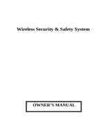
P.I.R Motion Detector
63 DOOR SENSOR
01 Open
Backup Bat Low
MESSAGE DELETED
18
The PIR Motion Detector is designed to detect the movement of object in rooms or hallway.
The effective range of the motion sensor is 30 feet long, and with an 84 degree horizontal
angle.
Before using the sensor, the sensor needed to be learned into main console. If main
console is armed in HOME mode. Even if PIR Triggered, the main console will neglect the
PIR signal.
Main Features :
1. LED : When PIR has detected any moving of human. The red LED will blink for one
sec. It means to transmit out a signal to Main Console. When the battery power
is down to low level, It will send out a low voltage signal.
The red LED will blink for one sec. If Main Console receive the signal, will leave
some message on the display.
2. C/OFF/W SWITCH :
When the switch is set on “C – Continue” position, the PIR continually
detects at interval every 3 to 5 seconds after detecting the movement
of human (dog ,cat).It is an idea for checking
When the switch is set on “ OFF” position, It will turn off the power, the
PIR does not detect at all.
When the switch is set on “W- Wait” position, the PIR detects at every
2 minutes to 3 minutes after detecting the movement of human ( dog,
cat). “ W ” position set mode will save the power.
3. DETECTING SENSITIVITY : (1 , 2 , 4) select the sensor to high , medium or low
sensitivity.
4. BATTERY : Remove the Battery cover and insert one 9V alkaline battery.
5. ARM & HOLDER : For mounting on the wall.
6. BATTERY COVER
Replace the Battery
19
When the sensor send the low battery voltage signal to main console.
Please replace a new battery for the sensor. In the main console, the LCD
display shown the message as below
Zone Address Setting
Enter the Installer password and the main console is in learning mode, after installing the
battery on the PIR. Set the power switch from “ OFF ” to “ C ” position. In the PIR panel,
The red LED will blink for 1 sec, It means to transmit out a signal for 1 sec or to activate
PIR sensor by detecting people pass by, then the Main Console emits one ‘Beep’ and LCD
displays ‘In Memory’, it means the PIR has learned into the system successfully.
When main console is in armed mode, If PIR detects the movement of human or
animals (cat, dog), it will leave message on the LCD display as below.
Notes on the Position when Install
Motion sensors detect the movement of humans and animals within their range. In order to
prevent false alarms, we recommend that you do not install any motion sensor in the
following areas:
Do not install any motion sensor in the following areas:
Where there is a device that causes rapid temperature change or rapid heat
transfer. for instance, near an air conditioner, fire place, heater or other
intermittent heat sources.
Where the sensor will be exposed to direct sunlight.
Near large electrical devices and/or high output radio frequency sources, like
the refrigerator, microwaves computers, and light dimmers.
Where the effective range of the sensor is covered or blocked by furniture.
Where pets enter and exit freely, for instance - a cat or dog door.
Directly opposite any large object with flat reflecting properties, like large
windows or mirrors.
In a bathroom or other area that is exposed to moisture and extreme
temperature change.
Installing the Motion Sensor
63 PIR SENSOR
01 Low battery
63 PIR SENSOR
01 Zone
20
Before installing the sensor, consider the following points:
Mount the sensor at two meters (6-1/2’) high for best coverage.
Mount the sensor with a 14 degree downward incline against the wall for optimum
range.
To install the Motion Sensor, please follow these steps:
Take out the screws or double sided adhesive and install the mounting bracket on
the wall. press the ball joint portion into the bracket until it snaps securely.( To
secure the mounting bracket to the wall at 2 meters above the floor).
Put the PIR on the mounting bracket.
Test the sensor by walking within its range. When the sensor is triggered, the red
LED light will flash once for 1 sec
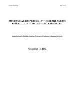
Door/Window Detector
21
The magnetic Door/Window detector is a contact sensor applied on door or window. When
the magnetic contact is opened (broken) or the battery is in low level, the sensor will send
out the signal to main console. The message of the triggered sensor can be read from the
Main Console’s LCD display.
Door/Window Detector (for DC 12V battery)
Button Function:
1.Magnet
2.Transmit LED :
When the sensor is
activated, LED will light for 1
sec.
3.Magnet Sensor
4.Battery Cover :
Remove the cover and put
one 12V alkaline battery
here.
Door/Window Detector (for DC 9V battery)
Button function
1. Magnet.
22
2. Magnetic Switch
3. Transmit LED : When the sensor is activated, LED will light for 1 sec.
4. Magnet sensor
5. Battery Cover : Remove the cover then put one 9V alkaline battery here.
Note: Magnet and magnet switch needed to be placed on parallel position (triangle arrow)
to ensure the better setting.
Change the Battery
When the sensor sends the low battery signal to main console, please replace a new
Battery for the sensor, in the meantime the LCD display shown the low battery message
as below.
Zone address setting
You can set the sensor as “ Door “ or “ Window “ detector by using the jumper selector and
follow the marked. Ex. You want to set the sensor as Door sensor, put the Jumper on
marked “D” side. (If set Jumper on marked “W” side, the sensor becomes as Window
sensor).
DOOR
DOOR / WINDOW
SELECT
JUMPER
TYPE SEL
WINDOW
DOOR / WINDOW
SELECT
WINDOW
DOOR
JUMPER
TYPE SEL
DC 12V
DC 9V
Notes on the Door/Window Detector
1. The LED on the sensor will flash once when the sensor is triggered.
2. There cannot be a gap greater than 1/4 inch (5 mm) between the magnet sensor and
the magnet, otherwise, the sensor will not work properly.
Enter the installer password and let main console in learning mode. take magnet away
from magnet sensor, it will trigger the sensor and LED will light on for 1 sec. the Main
Console emits one ‘Beep’ and LCD displays ‘In Memory’, it means sensor has learned into
63 WINDOW SENSOR
01 Low battery
23
the system successfully.
LCD display on the Main Console for Door/Window Detector
When system is in armed mode. (message shown on main console)
Window opened Door opened
When system is in disarm mode. (message shown on main console)
Window closed
Window battery cover opened Door battery cover opened
I
nstalling the Door/Window Detector
Installing for( DC 12V Detector):
To install a Door/Window Detector, follow these steps:
1. Before installing the sensor, ensure the sensor has learned in main console
successfully
2. Apply double aided adhesive tape to the back of the sensor.
3. Find the arrow embossed on the sensor, just below the LED light. Find a similar arrow
on the magnet. Before exposing the adhesive backing, align the two arrows on the
surface where you want them installed. Check that both parts of the device fit and that
they can be mounted with a gap less than 1/4 inch between them.( refer to below
picture).
4. When finished the above procedure, please reconfirm the setting is correct or not, in
main console, Press the CHECK button then open the window. The main console will
receive the sensor signal and leave some messages on LCD display.
Installing for( DC 9V Detector):
To install a Door/Window Detector, follow these steps:
1. Before installing the sensor, ensure the sensor has learned in main console
successfully
2. You can select the double aided adhesive tape or screw to install the sensor.
3. If you use the double aided adhesive tape to install the sensor, please refer to DC 12V
Detector installing process 2- 4 to set the sensor.
4. If you use the rivet and screw to install the sensor, please follow the step
Please use the fix sticker on the wall and pinch two holes to install the rivet and screws
5. Use DC 9V Detector back cover with two holes to put on the screws.
6. Use the magnet to set near the door/window frame. Find the arrow embossed on the
sensor, just below the LED light. Find a similar arrow on the magnet. Before exposing
63 WINDOW SENSOR
01 Open
63 DOOR SENSOR
01 Open
63 WINDOW SENSOR
01 Close
63 WINDOW SENSOR
01 Tamper
63 DOOR SENSOR
01 Tamper
24
the adhesive backing, align the two arrows on the surface where you want them
installed. Check that both parts of the device fit and that they can be mounted with a gap
less than 1/4 inch between them.( refer to below picture)
7. When finished the above procedure, please reconfirm the setting is correct or not, in
main console, Press the CHECK button then open the window. The main console will
receive the sensor signal and leave some messages on LCD display.
INSTALLING POSITION REFERENCE FOR DOOR/WINDOW DETECTOR
Remote Control Handset