SIEMENS - simatic standard software for S7-300 and S7-400 standard functions part 2 ppt
Bạn đang xem bản rút gọn của tài liệu. Xem và tải ngay bản đầy đủ của tài liệu tại đây (480.63 KB, 106 trang )
Preface, Contents
Bit Logic Functions
1
Table Functions
2
Shift Functions
3
Move Function and Function
Block
4
Timer Functions and Function
Blocks
5
Convert Functions and Function
Blocks
6
Floating Point Math Function
7
Compare Function Blocks
8
Glossary, Index
03/2000
Edition 03
Standard Software for S7-300
and S7-400
Standard Functions Part 2
Reference Manual
SIMATIC
This manual contains notices which you should observe to ensure your own personal safety,
as well as to protect the product and connected equipment. These notices are highlighted
in the manual by a warning triangle and are marked as follows according to the level of
hazard.
!
indicates an imminently hazardous situation that, if not avoided, will result in death or
serious injury. Danger is limited to the most extreme situations.
Danger
!
indicates that death, severe personal injury, or substantial property damage can
result.You must take proper precautions.
Warning is used for personal injury and also for property damage.
Warning
!
indicates that minor personal injury or property damage can result if proper
precautions are not taken. Caution is also used for property-damage-only accidents.
Caution
Note
draws your attention to particularly important information on the product, handling the product, or
to a particular part of the documentation.
This device should only be set up and operated in conjunction with this manual.
Only qualified personnel should be allowed to install and work on this equipment. Qualified
persons are defined as persons who are authorized to commission, to ground and to tag
equipment, systems and circuits in accordance with established safety practices and
standards.
Note the following:
!
Warning
This device may only be used for the applications described in the catalog or
technical description, and only in connection with devices or components from
other manufacturers which have been approved or recommended by Siemens.
This product can only function correctly and safely if it is transported, stored and
set up carefully and correctly, and operated and maintained as recommended.
Trademarks SIMATIC, SIMATIC HMI and SIMATIC NET are registered trademarks of SIEMENS AG.
Third parties using for their own purposes any other names in this document which refer to
trademarks might infringe upon the rights of the trademark owners.
We have checked the contents of this manual for agreement with the
hardware and software described. Since deviations cannot be
precluded entirely, we cannot guarantee full agreement. However,
the data in this manual are reviewed regularly and any necessary
corrections included in subsequent editions. Suggestions for
improvement are welcomed.
Disclaimer of LiabilityCopyright {Siemens AG 2000 All rights reserved
The reproduction, transmission or use of this document or its
contents is not permitted without express written authority.
Offenders will be liable for damages. All rights, including rights
created by patent grant or registration of a utility model or design, are
reserved.
Siemens AG
Bereich Automatisierungs- und Antriebstechnik
Geschaeftsgebiet Industrie-Automatisierungssysteme
Postfach 4848, D-90327 Nuernberg
Siemens AG 2000
Subject to technical change.
Siemens Aktiengesellschaft 6ES7811-4AA00-0BX0
Safety guidelines
Qualified personnel
Correct usage
iii
Standard Software for S7-300 and S7-400 Standard Functions Part 2
A5E00066867-03
Preface
This manual provides descriptions and examples of S7 functions FCs and
function blocks FBs in ladder logic (LAD) representation. These FCs and
FBs are available to program your S7-300/S7-400 programmable logic
controller (PLC). This manual is intended as a reference to provide the
necessary information for each function.
The FCs and FBs described in this manual are located in the Standard Library
of STEP 7. Using your STEP 7 file manager, you can copy the FCs and FBs
you need to your destination program directory. First make certain that your
program does not contain any FCs or FBs with the same number as the ones
you want to copy from the library. If you have FCs or FBs with matching
numbers, you must renumber either your program FCs or FBs, or the one(s)
you want to copy to your program.
This manual is intended for engineers, programmers, and maintenance
personnel who have a general knowledge of programmable logic controllers.
This manual groups the FCs and FBs into the following functional areas:
• Bit logic functions (Chapter 1)
• Table functions (Chapter 2)
• Shift functions (Chapter 3)
• Move functions and function blocks (Chapter 4)
• Timer functions and function blocks (Chapter 5)
• Convert functions and function blocks (Chapter 6)
• Floating Point Math functions (Chapter 7)
• Compare function blocks (Chapter 8)
• The glossary provides an alphabetical listing of definitions of key terms
and expressions that are applicable to ladder logic programming.
Purpose
Where to Find
the S7 Functions
Audience
How to Use This
Manual
iv
Standard Software for S7-300 and S7-400 Standard Functions Part 2
A5E00066867-03
Each chapter describes FCs and FBs that you can add to your standard set of
instructions to provide additional programming flexibility. Each FC or FB is
listed with the full name, the abbreviation, and the FC or FB number. Each
FC or FB is described according to the following topics:
• Description — a basic functional description.
• Parameters — a table giving the declaration, data type, valid memory
areas, and the description for each parameter.
• Error Information — errors that would prevent the FC or FB from being
executed successfully.
• Example — a figure consisting of a graphic representation of the FC or
FB with example parameters and the results of the execution.
This manual is a part of the STEP 7 documentation package that consists of
the manuals listed in the following table.
Title Content
Working with STEP 7,
Getting Started
The manual offers a basic introduction to the methodology of the structure and
programming of an S7-300/S7-400. It is especially suited to first-time users of an S7
programmable control system.
Programming with
STEP 7
Manual
This manual provides basic information on the structure of the operating system and of
a user program of an S7 CPU. The first-time user of an S7-300 or S7-400 should use
this manual to acquire an overview of the programming methodology and to use it to
base their user program design on.
System Software for
S7-300 and S7-400
System and Standard
Functions
Reference Manual
The S7 CPUs have integrated system functions and organization blocks included with
their operating system, which you can use when programming. The manual provides
you with an overview of the system functions, organization blocks, and loadable
standard functions available in S7, and – in the form of reference information – detailed
interface descriptions for their use in your user program.
Configuring Hardware
and Communication
Connections STEP 7
Manual
The STEP 7 Manual explains the main usage and the functions of the STEP 7
automation software. As a first-time user of STEP 7 and as an experienced user of
STEP 5, this manual will provide you with an overview of the procedures used to
configure, program, and start up an S7-300/S7-400.
While you are working with the software you can access a range of on-line help topics
which offer detailed support on using the software.
From S5 to S7
Converter Manual
You will need the Converting STEP 5 Programs Manual if you want to convert existing
STEP 5 programs to run them on S7 CPUs. The manual provides an overview of the
procedures and usage of the Converter; you can find a detailed description of the
converter functions in the on-line help. You will also find the interface descriptions for
the converted S7 functions available in the on-line help.
Statement List, Ladder
Logic, SCL
1
Reference Manuals
The manuals for the programming language packages Statement List, Ladder Logic,
and SCL (Sequential Control Language) contain both the user’s guide and the reference
description of the programming language or representation type. You only require one
language type for programming an S7-300/S7-400, but you can mix the languages
within a project, if required. If you are using a language for the first time, it is
recommended that you use the manual to learn about the methodology of creating a
program in the chosen language first.
While you are working with the software you can access a range of on-line help topics
which offer detailed support on using the respective editors/compilers.
Overview of the
STEP 7
Documentation Set
Preface
v
Standard Software for S7-300 and S7-400 Standard Functions Part 2
A5E00066867-03
Title Content
S7-GRAPH
1
,
S7-HiGraph
1
, CFC
1
Manuals
The languages S7-GRAPH, S7-HiGraph, and CFC (Continuous Function Chart) offer
additional methods of programming blocks in the form of sequential controls, state
graphs, or charts. The manuals contain both the user’s guide and the reference
description of the programming language. If you are using a language for the first time,
it is recommended that you use the manual to learn about the methodology of creating a
program in the chosen language first.
While you are working with the software you can access a range of on-line help topics
which offer detailed support on using the respective editors/compilers (with the
exception of HiGraph).
1 Optional package for system software for S7-300/S7-400
The various S7-300 and S7-400 CPUs, the S7-300 and S7-400 modules, and
the instructions of the CPU are described in the following manuals:
• For the S7-300 programmable logic controller, refer to the manuals:
Hardware and Installation (CPU Data, Module Data) and the Instruction
List.
• For the S7-400 programmable logic controller, refer to the manuals:
Hardware and Installation (CPU Data, Module Data) and the Instruction
List.
You can find additional information in the on-line help.
If you have any questions not answered in this or one of the other STEP 7
manuals, if you need information on ordering additional documentation or
equipment, or if you need information on training, please contact your
Siemens distributor or sales office.
Other Manuals
Additional
Assistance
Preface
vi
Standard Software for S7-300 and S7-400 Standard Functions Part 2
A5E00066867-03
The following functions and function blocks are described in this manual:
Function or Function Block Number Page
Software Timer On Delay—Retentive (TONR) FC80 5-2
Indirect Block Move (IBLKMOV) FC81 4-2
Reset Range of Outputs (RSET) FC82 1-2
Set Range of Outputs (SET) FC83 1-6
Add to Table (ATT) FC84 2-2
First In/First Out Unload Table (FIFO) FC85 2-4
Table Find (TBL_FIND) FC86 2-6
Last In/First Out Unload Table (LIFO) FC87 2-9
Table (TBL) FC88 2-11
Move Table to Word (TBL_WRD) FC89 2-13
Word Shift Register (WSR) FC90 3-2
Word to Table (WRD_TBL) FC91 2-15
Bit Shift Register (SHRB) FC92 3-4
Seven Segment Decoder (SEG) FC93 6-2
ASCII to Hex (ATH) FC94 6-4
Hex to ASCII (HTA) FC95 6-6
Encode Binary Position (ENCO) FC96 6-8
Decode Binary Position (DECO) FC97 6-9
Ten’s Complement (BCDCPL) FC98 6-10
Sum Number of Bits (BITSUM) FC99 6-11
Reset Range of Immediate Outputs (RSETI) FC100 1-4
Set Range of Immediate Outputs (SETI) FC101 1-8
Standard Deviation (DEV) FC102 7-2
Correlated Data Table (CDT) FC103 2-17
Table to Table (TBL_TBL) FC104 2-19
Scaling Values (SCALE) FC105 6-12
Unscaling Values (UNSCALE) FC106 6-14
Lead/Lag Algorithm (LEAD_LAG) FB80 6-16
Discrete Control Alarm Timer (DCAT) FB81 5-4
Motor Control Alarm Timer (MCAT) FB82 5-7
Index Matrix Compare (IMC) FB83 8-2
Scan Matrix Compare (SMC) FB84 8-6
Event Maskable Drum (DRUM) FB85 5-10
Pack Data (PACK) FB86 4-4
List of Functions
and Function
Blocks
Preface
vii
Standard Software for S7-300 and S7-400 Standard Functions Part 2
A5E00066867-03
Contents
1 Bit Logic Functions 1-1. . . . . . . . . . . . . . . . . . . . . . . . . . . . . . . . . . . . . . . . . . . . .
1.1 Reset Range of Outputs (RSET): FC82 1-2. . . . . . . . . . . . . . . . . . . .
1.2 Reset Range of Immediate Outputs (RSETI): FC100 1-4. . . . . . . . .
1.3 Set Range of Outputs (SET): FC83 1-6. . . . . . . . . . . . . . . . . . . . . . . .
1.4 Set Range of Immediate Outputs (SETI): FC101 1-8. . . . . . . . . . . .
2 Table Functions 2-1. . . . . . . . . . . . . . . . . . . . . . . . . . . . . . . . . . . . . . . . . . . . . . . .
2.1 Add to Table (ATT): FC84 2-2. . . . . . . . . . . . . . . . . . . . . . . . . . . . . . . .
2.2 First In/First Out Unload Table (FIFO): FC85 2-4. . . . . . . . . . . . . . .
2.3 Table Find (TBL_FIND): FC86 2-6. . . . . . . . . . . . . . . . . . . . . . . . . . . .
2.4 Last In/First Out Unload Table (LIFO): FC87 2-9. . . . . . . . . . . . . . . .
2.5 Table (TBL): FC88 2-11. . . . . . . . . . . . . . . . . . . . . . . . . . . . . . . . . . . . . . .
2.6 Move Table to Word (TBL_WRD): FC89 2-13. . . . . . . . . . . . . . . . . . . .
2.7 Word to Table (WRD_TBL): FC91 2-15. . . . . . . . . . . . . . . . . . . . . . . . .
2.8 Correlated Data Table (CDT): FC103 2-17. . . . . . . . . . . . . . . . . . . . . .
2.9 Table To Table (TBL_TBL): FC104 2-19. . . . . . . . . . . . . . . . . . . . . . . .
3 Shift Functions 3-1. . . . . . . . . . . . . . . . . . . . . . . . . . . . . . . . . . . . . . . . . . . . . . . . .
3.1 Word Shift Register (WSR): FC90 3-2. . . . . . . . . . . . . . . . . . . . . . . . .
3.2 Bit Shift Register (SHRB): FC92 3-4. . . . . . . . . . . . . . . . . . . . . . . . . . .
4 Move Function and Function Block 4-1. . . . . . . . . . . . . . . . . . . . . . . . . . . . . .
4.1 Indirect Block Move (IBLKMOV): FC81 4-2. . . . . . . . . . . . . . . . . . . . .
4.2 Pack Data (PACK): FB86 4-4. . . . . . . . . . . . . . . . . . . . . . . . . . . . . . . .
5 Timer Function and Function Blocks 5-1. . . . . . . . . . . . . . . . . . . . . . . . . . . . .
5.1 Software Timer On Delay—Retentive (TONR): FC80 5-2. . . . . . . . .
5.2 Discrete Control Alarm Timer (DCAT): FB81 5-4. . . . . . . . . . . . . . . .
5.3 Motor Control Alarm Timer (MCAT): FB82 5-7. . . . . . . . . . . . . . . . . .
5.4 Event Maskable Drum (DRUM): FB85 5-10. . . . . . . . . . . . . . . . . . . . .
6 Convert Functions and Function Block 6-1. . . . . . . . . . . . . . . . . . . . . . . . . .
6.1 Seven Segment Decoder (SEG): FC93 6-2. . . . . . . . . . . . . . . . . . . . .
6.2 ASCII to Hex (ATH): FC94 6-4. . . . . . . . . . . . . . . . . . . . . . . . . . . . . . . .
6.3 Hex to ASCII (HTA): FC95 6-6. . . . . . . . . . . . . . . . . . . . . . . . . . . . . . . .
6.4 Encode Binary Position (ENCO): FC96 6-8. . . . . . . . . . . . . . . . . . . . .
6.5 Decode Binary Position (DECO): FC97 6-9. . . . . . . . . . . . . . . . . . . . .
viii
Standard Software for S7-300 and S7-400 Standard Functions Part 2
A5E00066867-03
6.6 Tens Complement (BCDCPL): FC98 6-10. . . . . . . . . . . . . . . . . . . . . . .
6.7 Sum Number of Bits (BITSUM): FC99 6-11. . . . . . . . . . . . . . . . . . . . . .
6.8 Scaling Values (SCALE): FC105 6-12. . . . . . . . . . . . . . . . . . . . . . . . . .
6.9 Unscaling Values (UNSCALE): FC106 6-14. . . . . . . . . . . . . . . . . . . . .
6.10 Lead/Lag Algorithm (LEAD_LAG): FB80 6-16. . . . . . . . . . . . . . . . . . .
7 Floating Point Math Function 7-1. . . . . . . . . . . . . . . . . . . . . . . . . . . . . . . . . . . .
7.1 Standard Deviation (DEV): FC102 7-2. . . . . . . . . . . . . . . . . . . . . . . . .
8 Compare Function Blocks 8-1. . . . . . . . . . . . . . . . . . . . . . . . . . . . . . . . . . . . . . .
8.1 Index Matrix Compare (IMC): FB83 8-2. . . . . . . . . . . . . . . . . . . . . . . .
8.2 Scan Matrix Compare (SMC): FB84 8-6. . . . . . . . . . . . . . . . . . . . . . .
Glossary Glossary-1. . . . . . . . . . . . . . . . . . . . . . . . . . . . . . . . . . . . . . . . . . . . . . . . . . . . . . .
Index Index-1. . . . . . . . . . . . . . . . . . . . . . . . . . . . . . . . . . . . . . . . . . . . . . . . . . . . . . . . . .
Contents
1-1
Standard Software for S7-300 and S7-400 Standard Functions Part 2
A5E00066867-03
Bit Logic Functions
This chapter describes the bit logic functions (FCs) that you can add to your
standard set of instructions to provide additional programming flexibility.
Section Description Page
1.1 Reset Range of Outputs (RSET): FC82 1-2
1.2 Reset Range of Immediate Outputs (RSETI):
FC100
1-4
1.3 Set Range of Outputs (SET): FC83 1-6
1.4 Set Range of Immediate Outputs (SETI): FC101 1-8
1
1-2
Standard Software for S7-300 and S7-400 Standard Functions Part 2
A5E00066867-03
1.1 Reset Range of Outputs (RSET): FC82
The Reset Range of Outputs (RSET) function resets the signal state of each
bit in a specified range to 0 if the MCR bit is 1. If the MCR bit is 0, the
signal state of each bit in the range remains unchanged. The number of bits in
the range to be reset is specified by N, and the starting point of the range is
pointed to by S_BIT.
Table 1-1 describes the Reset Range of Outputs (RSET) parameters.
Table 1-1 Reset Range of Outputs (FC82) Parameters
Parameter
Declaration Data Type Memory Area Description
EN Input BOOL I, Q, M, D, L Enable input with signal state of 1 activates the box
ENO Output BOOL I, Q, M, D, L Enable output has a signal state of 1 if the function
is executed without error
S_BIT Input Pointer* I, Q, M, D Points to the first bit in the range
N Input INT I, Q, M, D, L, P
or constant
Number of bits in the range to be reset
*Double word pointer format for area-crossing register indirect addressing
Description
Parameters
Bit Lo
g
ic Functions
1-3
Standard Software for S7-300 and S7-400 Standard Functions Part 2
A5E00066867-03
If the S_BIT pointer references the I/O external input and output memory
area (P memory), the signal state of each bit in the range remains unchanged
and the signal state of ENO is set to 0.
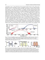
Figure 1-1 shows how the RSET instruction works. If the signal state of input
I 0.0 is 1 (activated) and the MCR bit is 1, the RSET function is executed. In
this example, S_BIT points to the first bit at location M0.0. The N parameter
specifies 10 bits to be reset. After the instruction is executed, the signal state
of each of the 10 bits in the range M0.0 through M1.1 is reset to 0.
If the function is executed without error, the signal states of ENO and Q 4.0
are set to 1.
I 0.0 Q 4.0
RSET
FC82
EN ENO
S_BIT
N
P#M0.0
10
1
M0.0
Before execution:
1 1 1 1 1 11
1
M1.0
1 1 1 1 1 11
0
M0.0
After execution:
0 0 0 0 0 00
1
M1.0
1 1 1 1 1 00
M0.7
M1.7
M0.7
M1.7
Figure 1-1 Reset Range of Outputs (RSET)
Error Information
Example
Bit Lo
g
ic Functions
1-4
Standard Software for S7-300 and S7-400 Standard Functions Part 2
A5E00066867-03
1.2 Reset Range of Immediate Outputs (RSETI): FC100
The Reset Range of Immediate Outputs (RSETI) function resets the signal
state of a range of bytes to 0 if the MCR bit is 1. If the MCR bit is 0, the
signal state of each byte in the range remains unchanged. S_BYTE points to
the first byte in the range, and N specifies the size of the range. The size of
the range is expressed by specifying the number of bits in the range. For
example, to specify a range of 2 bytes, you would enter 16 (16 bits) for the
value of N.
Note
The value of N must be a multiple of eight (for example, 8, 16, 24, etc.).
The S_BYTE pointer must reference the external input and output memory
area (P memory). Since P memory is accessed as bytes, words, or double
words, the S_BYTE must reference an address that is byte-aligned, which
means that the bit number of the pointer must be 0.
Note
The signal state of the corresponding bits in the process-image output table
(Q memory) is also reset to 0.
Table 1-2 describes the Reset Range of Immediate Outputs (RSETI)
parameters.
Table 1-2 Reset Range of Immediate Outputs (FC100) Parameters
Parameter
Declaration Data Type Memory Area Description
EN Input BOOL I, Q, M, D, L Enable input with signal state of 1 activates the box
ENO Output BOOL I, Q, M, D, L Enable output has a signal state of 1 if the function
is executed without error
S_BYTE Input Pointer* P Points to the first byte in the range
N Input INT I, Q, M, D, L, P
or constant
Size of the range of bytes to be reset to 0, specified
by the number of bits in multiples of 8, (for
example, 8, 16, etc.)
*Double word pointer format for area-crossing register indirect addressing
Description
Parameters
Bit Lo
g
ic Functions
1-5
Standard Software for S7-300 and S7-400 Standard Functions Part 2
A5E00066867-03
If any of the following conditions occur, the signal state of each bit in the
range remains unchanged and the signal state of ENO is set to 0.
• The S_BYTE pointer references a memory area other than the I/O
external input and output memory area (P memory).
• The S_BYTE pointer references an address that is not byte-aligned.
• The value of N is not a multiple of eight.
Figure 1-2 shows how the RSETI instruction works. If the signal state of
input I 0.0 is 1 (activated) and the MCR bit is 1, the RSETI function is
executed. In this example, S_BYTE points to the first byte at location P2.0.
The N parameter specifies 16 bits (2 bytes) to be reset. After the instruction
is executed, the signal state of each bit in the range P2.0 through P3.7 is reset
to 0.
If the function is executed without error, the signal states of ENO and Q 4.0
are set to 1.
I 0.0 Q 4.0
RSETI
FC100
EN ENO
S_BYTE
N
P#P2.0
16
1
P1.0
Before execution:
1 1 1 1 1 11
1
P2.0
1 1 1 1 1 11
1
P3.0
1 1 1 1 1 11
1
P4.0
1 1 1 1 1 11
After execution:
1
P1.0
1 1 1 1 1 11
0
P2.0
0 0 0 0 0 00
0
P3.0
0 0 0 0 0 00
1
P4.0
1 1 1 1 1 11
P1.7
P2.7
P3.7
P4.7
P1.7
P2.7
P3.7
P4.7
Figure 1-2 Reset Range of Immediate Outputs (RSETI)
Error Information
Example
Bit Lo
g
ic Functions
1-6
Standard Software for S7-300 and S7-400 Standard Functions Part 2
A5E00066867-03
1.3 Set Range of Outputs (SET): FC83
The Set Range of Outputs (SET) function sets the signal state of each bit in a
specified range to 1 if the MCR bit is 1. If the MCR bit is 0, the signal state
of each of the bits in the range remains unchanged. The number of bits in the
range to be set is specified by N, and the starting point of the range is pointed
to by S_BIT.
Table 1-3 describes the Set Range of Outputs (SET) parameters.
Table 1-3 Set Range of Outputs (FC83) Parameters
Parameter
Declaration Data Type Memory Area Description
EN Input BOOL I, Q, M, D, L Enable input with signal state of 1 activates the box
ENO Output BOOL I, Q, M, D, L Enable output has a signal state of 1 if the function
is executed without error
S_BIT Input Pointer* I, Q, M, D Points to the first bit in the range
N Input INT I, Q, M, D, L, P
or constant
Number of bits in the range to be set
*Double word pointer format for area-crossing register indirect addressing
Description
Parameters
Bit Lo
g
ic Functions
1-7
Standard Software for S7-300 and S7-400 Standard Functions Part 2
A5E00066867-03
If the S_BIT pointer references the I/O external input and output memory
area (P memory), the signal state of each bit in the range remains unchanged
and the signal state of ENO is set to 0.
Figure 1-3 shows how the SET instruction works. If the signal state of input
I 0.0 is 1 (activated) and the MCR bit is 1, the SET function is executed. In
this example, S_BIT points to the first bit at location M0.0. The N parameter
specifies 10 bits to be set. After the instruction is executed, the signal state of
each of the 10 bits in the range M0.0 through M1.1 is set to 1.
If the function is executed without error, the signal states of ENO and Q 4.0
are set to 1.
I 0.0 Q 4.0
SET
FC83
EN ENO
S_BIT
N
P#M0.0
10
0
M0.0
Before execution:
0 0 0 0 0 00
0
M1.0
0 0 0 0 0 00
1
M0.0
After execution:
1
0 0 0 0 110
M1.0
0
1 1 1 1 11
M0.7
M1.7
M0.7
M1.7
Figure 1-3 Set Range of Outputs (SET)
Error Information
Example
Bit Lo
g
ic Functions
1-8
Standard Software for S7-300 and S7-400 Standard Functions Part 2
A5E00066867-03
1.4 Set Range of Immediate Outputs (SETI): FC101
The Set Range of Immediate Outputs (SETI) function sets the signal state of
a range of bytes to 1 if the MCR bit is 1. If the MCR bit is 0, the signal state
of each byte in the range remains unchanged. S_BYTE points to the first byte
in the range, and N specifies the size of the range. The size of the range is
expressed by specifying the number of bits in the range. For example, to
specify a range of 2 bytes, you would enter 16 (16 bits) for the value of N.
Note
The value of N must be a multiple of eight (for example, 8, 16, 24, etc.).
The S_BYTE pointer must reference the external input and output memory
area (P memory). Since P memory is accessed as bytes, words, or double
words, the S_BYTE must reference an address that is byte-aligned, which
means that the bit number of the pointer must be 0.
Note
The signal state of the corresponding bits in the process-image output table
(Q memory) is also reset to 0.
Table 1-4 describes the Set Range of Immediate Outputs (SETI) parameters.
Table 1-4 Set Range of Immediate Outputs (FC101) Parameters
Parameter
Declaration Data Type Memory Area Description
EN Input BOOL I, Q, M, D, L Enable input with signal state of 1 activates the box
ENO Output BOOL I, Q, M, D, L Enable output has a signal state of 1 if the function
is executed without error
S_BYTE Input Pointer* P Points to the first byte in the range
N Input INT I, Q, M, D, L, P
or constant
Size of the range of bytes to be set to 1, specified by
the number of bits in multiples of 8 (for example, 8,
16, etc.)
*Double word pointer format for area-crossing register indirect addressing
Description
Parameters
Bit Lo
g
ic Functions
1-9
Standard Software for S7-300 and S7-400 Standard Functions Part 2
A5E00066867-03
If any of the following conditions occur, the signal state of each bit in the
range remains unchanged and the signal state of ENO is set to 0.
• The S_BYTE pointer references a memory area other than the I/O
external inputs and outputs (P) memory area.
• The S_BYTE pointer references an address that is not byte-aligned.
• The value of N is not a multiple of eight.
Figure 1-4 shows how the SETI instruction works. If the signal state of input
I 0.0 is 1 (activated) and the MCR bit is 1, the SETI function is executed. In
this example, S_BYTE points to the first byte at location P2.0. The N
parameter specifies 16 bits (2 bytes) to be set. After the instruction is
executed, the signal state of each bit in the range P2.0 through P3.7 is set
to 1.
If the function is executed without error, the signal states of ENO and Q 4.0
are set to 1.
I 0.0 Q 4.0
SETI
FC101
EN ENO
S_BYTE
N
P#P2.0
16
P1.0
Before execution: After execution:
P2.0
P3.0
P4.0
1
P1.0
1 1 1 1 1 11
0
P2.0
0 0 0 0 0 00
0
P3.0
0 0 0 0 0 00
1
P4.0
1 1 1 1 1 11
00000000
00000000
00000000
00000000
P1.7
P2.7
P3.7
P4.7
P1.7
P2.7
P3.7
P4.7
Figure 1-4 Set Range of Immediate Outputs (SETI)
Error Information
Example
Bit Lo
g
ic Functions
1-10
Standard Software for S7-300 and S7-400 Standard Functions Part 2
A5E00066867-03
Bit Lo
g
ic Functions
2-1
Standard Software for S7-300 and S7-400 Standard Functions Part 2
A5E00066867-03
Table Functions
This chapter describes the table functions (FCs) that you can add to your
standard set of instructions to provide additional programming flexibility.
Section Description Page
2.1 Add to Table (ATT): FC84 2-2
2.2 First In/First Out Unload Table (FIFO): FC85 2-4
2.3 Table Find (TBL_FIND): FC86 2-6
2.4 Last In/First Out Unload Table (LIFO): FC87 2-9
2.5 Table (TBL): FC88 2-11
2.6 Move Table to Word (TBL_WRD): FC89 2-13
2.7 Word to Table (WRD_TBL): FC91 2-15
2.8 Correlated Data Table (CDT): FC103 2-17
2.9 Table To Table (TBL_TBL): FC104 2-19
2
2-2
Standard Software for S7-300 and S7-400 Standard Functions Part 2
A5E00066867-03
2.1 Add to Table (ATT): FC84
The Add to Table (ATT) function adds DATA into the next entry of a table
and increments the number of entries by one. The table consists of words.
This function allows you to add entries into tables for use by the FIFO and
LIFO functions.
• The first entry in the FIFO or LIFO table contains the maximum number
of entries of the table (table length).
• The second entry in the table contains the number of entries entered.
• The third entry in the table contains the first word of data.
Note
You must initialize the first two entries when you create the table.
Table 2-1 describes the Add to Table (ATT) parameters.
Table 2-1 Add to Table (FC84) Parameters
Parameter
Declaration Data Type Memory Area Description
EN Input BOOL I, Q, M, D, L Enable input with signal state of 1 activates the box
ENO Output BOOL I, Q, M, D, L Enable output has a signal state of 1 if the function
is executed without error
DATA Input WORD I, Q, M, D, L, P
or constant
Data to add to table
TABLE Input Pointer* I, Q, M, D Points to the start of the FIFO or LIFO table
*Double word pointer format for area-crossing register indirect addressing
Description
Parameters
Table Functions
2-3
Standard Software for S7-300 and S7-400 Standard Functions Part 2
A5E00066867-03
If the number of entries is equal to or greater than the table length, the data
will not be added to the table and the signal state of ENO is set to 0.
Figure 2-1 shows how the ATT instruction works. If the signal state of input
I 0.0 is 1 (activated), the ATT function is executed. In this example, DATA is
added as the fifth entry in the table and the number of entries increments
from 4 to 5.
If the function is executed without error, the signal states of ENO and Q4.0
are set to 1.
I 0.0 Q 4.0
ATT
FC84
EN ENO
DATA
TABLE
W#16#0024
P#DB1.DBX10.0
Before execution:
Table (table length) DBW10 = W#16#0006
number of entries DBW12 = W#16#0004
DBW14 = W#16#0012
DBW16 = W#16#0029
DBW18 = W#16#0090
DBW20 = W#16#0002
DBW22 = W#16#0000
DBW24 = W#16#0000
After execution:
Table (table length) DBW10 = W#16#0006
number of entries DBW12 = W#16#0005
DBW14 = W#16#0012
DBW16 = W#16#0029
DBW18 = W#16#0090
DBW20 = W#16#0002
DBW22 = W#16#0024
DBW24 = W#16#0000
Figure 2-1 Add to Table (ATT)
Error Information
Example
Table Functions
2-4
Standard Software for S7-300 and S7-400 Standard Functions Part 2
A5E00066867-03
2.2 First In/First Out Unload Table (FIFO): FC85
The First In/First Out Unload Table (FIFO) function returns the oldest entry
from the FIFO table as the function value. The number of entries decrements
by one, and if more entries remain, they are shifted down in the table. The
FIFO table consists of words. You use the ATT function to add values into the
FIFO table.
• The first entry in the table contains the maximum number of entries of the
table (table length).
• The second entry in the table contains the number of entries entered.
• The third entry in the table contains the first word of data.
Table 2-2 describes the First In/First Out Unload Table (FIFO) parameters.
Table 2-2 First In/First Out Unload Table (FC85) Parameters
Parameter
Declaration Data Type Memory Area Description
EN Input BOOL I, Q, M, D, L Enable input with signal state of 1 activates the box
ENO Output BOOL I, Q, M, D, L Enable output has a signal state of 1 if the function
is executed without error
TABLE Input Pointer* I, Q, M, D Points to the start of the FIFO table
RET_VAL Output WORD I, Q, M, D, L, P The oldest entry from the FIFO table
*Double word pointer format for area-crossing register indirect addressing
Description
Parameters
Table Functions
2-5
Standard Software for S7-300 and S7-400 Standard Functions Part 2
A5E00066867-03
If the FIFO table is empty (number of entries = 0), the RET_VAL is not
changed and the signal state of ENO is set to 0.
Figure 2-2 shows how the FIFO instruction works. If the signal state of input
I 0.0 is 1 (activated), the FIFO function is executed. In this example, the
oldest entry in the table is returned as the function value (MW2). The number
of entries is decremented from 5 to 4, and the remaining entries are shifted
down in the table.
If the function is executed without error, the signal states of ENO and Q 4.0
are set to 1.
RET_VAL MW2 = W#16#0012
RET_VAL MW2 = W#16#0000
I 0.0 Q 4.0
P#DB1.DBX10.0
FIFO
FC85
TABLE
RET_VAL
EN ENO
MW2
Before execution:
Table (table length) DBW10 = W#16#0006
number of entries DBW12 = W#16#0005
DBW14 = W#16#0012
DBW16 = W#16#0029
DBW18 = W#16#0090
DBW20 = W#16#0002
DBW22 = W#16#0024
DBW24 = W#16#0000
After execution:
Table (table length) DBW10 = W#16#0006
number of entries DBW12 = W#16#0004
DBW14 = W#16#0029
DBW16 = W#16#0090
DBW18 = W#16#0002
DBW20 = W#16#0024
DBW22 = W#16#0024
DBW24 = W#16#0000
Figure 2-2 First In/First Out Unload Table (FIFO)
Error Information
Example
Table Functions
2-6
Standard Software for S7-300 and S7-400 Standard Functions Part 2
A5E00066867-03
2.3 Table Find (TBL_FIND): FC86
The Table Find (TBL_FIND) function is used to search for a distinct pattern
or to search for a non-consistent pattern in a block of memory. This function
performs the indicated compare command (CMD) between the source pattern
(PATRN) and the source table (SRC) entries. It locates the next entry (after
the entry indexed by INDX) in the table that satisfies the compare command
and places its entry number in INDX. If no match is found, INDX points past
the end of the table and the function’s output is turned off.
• If CMD = 1, the function searches for the first value equal to the PATRN
value.
• If CMD = 2, the function searches for the first value that is not equal to
the PATRN value.
• The first entry in the table contains the maximum number of entries of the
table (table length).
• The second entry in the table contains the first table value.
Note
You must initialize the first entry (table length) of the table.
Description
Table Functions
2-7
Standard Software for S7-300 and S7-400 Standard Functions Part 2
A5E00066867-03
Table 2-3 describes the Table Find (TBL_FIND) parameters.
Table 2-3 Table Find (FC86) Parameters
Parameter
Declaration Data Type Memory Area Description
EN Input BOOL I, Q, M, D, L Enable input with signal state of 1 activates the box
ENO Output BOOL I, Q, M, D, L Enable output has a signal state of 1 if the function
is executed without error
SRC Input Pointer* I, Q, M, D Points to the start of the table
PATRN Input Pointer* I, Q, M, D Points to the pattern to be searched for
CMD Input BYTE I, Q, M, D, L, P Indicates command type:
B#16#01 = equal
B#16#02 = not equal
E_TYPE Input BYTE I, Q, M, D, L, P Indicates the data type of the table entries. Valid data
types for the TBL_FIND function are as follows:
B#16#02 = BYTE
B#16#04 = WORD
B#16#05 = INT
B#16#06 = DWORD
B#16#07 = DINT
B#16#08 = REAL
RET_VAL Output WORD I, Q, M, D, L, P Returns a value of W#16#0000 if the instruction
executes without error; see Error Information for
values other than W#16#0000
INDX Input_Output WORD I, Q, M, D, L Index into table that provides:
Input: starting entry number of the search
Output: entry number of the matching value
*Double word pointer format for area-crossing register indirect addressing
If any of the conditions shown in Table 2-4 occur, the table values are not
changed. The signal state of ENO is set to 0 and the return value is set
appropriately (see Table 2-4).
Table 2-4 Error Conditions for FC86
RET_VAL Explanation
W#16#0008 No match was found
W#16#0009 Invalid E_TYPE and/or CMD
Parameters
Error Information
Table Functions