RF / Microwave Circuit Design for Wireless Application potx
Bạn đang xem bản rút gọn của tài liệu. Xem và tải ngay bản đầy đủ của tài liệu tại đây (20.49 MB, 972 trang )
RF/MICROWAVE CIRCUIT
DESIGN FOR WIRELESS
APPLICATIONS
RF/Microwave Circuit Design for Wireless Applications.
Ulrich L. Rohde, David P. Newkirk
Copyright © 2000 John Wiley & Sons, Inc.
ISBNs: 0-471-29818-2 (Hardback); 0-471-22413-8 (Electronic)
RF/MICROWAVE CIRCUIT
DESIGN FOR WIRELESS
APPLICATIONS
Ulrich L. Rohde
Synergy Microwave Corporation
David P. Newkirk
Ansoft Corporation
JOHN WILEY & SONS, INC.
New York Chichester Weinheim Brisbane Singapore Toronto/////
A WILEY- INTERSCIENCE PUBLICATION
Designations used by companies to distinguish their products are often claimed as trademarks. In all instances
where John Wiley & Sons, Inc., is aware of a claim, the product names appear in initial capital or ALL
CAPITAL LETTERS. Readers, however, should contact the appropriate companies for more complete
information regarding trademarks and registration.
Copyright © 2000 by John Wiley & Sons, Inc. All rights reserved.
No part of this publication may be reproduced, stored in a retrieval system or transmitted in any form or by any
means, electronic or mechanical, including uploading, downloading, printing, decompiling, recording or
otherwise, except as permitted under Sections 107 or 108 of the 1976 United States Copyright Act, without the
prior written permission of the Publisher. Requests to the Publisher for permission should be addressed to the
Permissions Department, John Wiley & Sons, Inc., 605 Third Avenue, New York, NY 10158-0012, (212)
850-6011, fax (212) 850-6008, E-Mail: PERMREQ @ WILEY.COM.
This publication is designed to provide accurate and authoritative information in regard to the subject matter
covered. It is sold with the understanding that the publisher is not engaged in rendering professional services. If
professional advice or other expert assistance is required, the services of a competent professional person should
be sought.
ISBN 0-471-22413-8
This title is also available in print as ISBN 0-471-29818-2.
For more information about Wiley products, visit our web site at www.Wiley.com.
To Professor Vittorio Rizzoli
who has been instrumental in the development of the powerful harmonic-balance
analysis tool, specifically Microwave Harmonica, which is part of Ansofts Serenade
Design Environment. Most of the success enjoyed by Compact Software, now part of
Ansoft, continues to be based on his far-reaching contributions.
v
CONTENTS
Foreword xiii
Preface xv
1 Introduction to Wireless Circuit Design 1
1-1 Overview / 1
1-2 System Functions / 3
1-3 The Radio Channel and Modulation Requirements / 5
1-3-1 Introduction / 5
1-3-2 Channel Impulse Response / 7
1-3-3 Doppler Effect / 13
1-3-4 Transfer Function / 14
1-3-5 Time Response of Channel Impulse Response and Transfer
Function / 14
1-3-6 Lessons Learned / 17
1-3-7 Wireless Signal Example: The TDMA System in GSM / 18
1-4 About Bits, Symbols, and Waveforms / 29
1-4-1 Introduction / 29
1-4-2 Some Fundamentals of Digital Modulation Techniques / 38
1-5 Analysis of Wireless Systems / 47
1-5-1 Analog and Digital Receiver Designs / 47
1-5-2 Transmitters / 58
1-6 Building Blocks / 81
1-7 System Specifications and Their Relationship to Circuit Design / 83
1-7-1 System Noise and Noise Floor / 83
1-7-2 System Amplitude and Phase Behavior / 88
1-8 Testing / 114
1-8-1 Introduction / 114
1-8-2 Transmission and Reception Quality / 114
1-8-3 Base-Station Simulation / 118
1-8-4 GSM / 118
vii
1-8-5 DECT / 118
1-9 Converting C/N or SNR to
E
b
/
N
0
/ 120
2 Models for Active Devices 123
2-1 Diodes / 124
2-1-1 Large-Signal Diode Model / 124
2-1-2 Mixer and Detector Diodes / 128
2-1-3 PIN Diodes / 135
2-1-4 Tuning Diodes / 153
2-2 Bipolar Transistors / 198
2-2-1 Transistor Structure Types / 198
2-2-2 Large-Signal Behavior of Bipolar Transistors / 199
2-2-3 Large-Signal Transistors in the Forward-Active Region / 209
2-2-4 Effects of Collector Voltage on Large-Signal Characteristics in the
Forward-Active Region / 225
2-2-5 Saturation and Inverse Active Regions / 227
2-2-6 Small-Signal Models of Bipolar Transistors / 232
2-3 Field-Effect Transistors / 237
2-3-1 Large-Signal Behavior of JFETs / 246
2-3-2 Small-Signal Behavior of JFETs / 249
2-3-3 Large-Signal Behavior of MOSFETs / 254
2-3-4 Small-Signal Model of the MOS Transistor in Saturation / 262
2-3-5 Short-Channel Effects in FETs / 266
2-3-6 Small-Signal Models of MOSFETs / 271
2-3-7 GaAs MESFETs / 301
2-3-8 Small-Signal GaAs MESFET Model / 310
2-4 Parameter Extraction of Active Devices / 322
2-4-1 Introduction / 322
2-4-2 Typical SPICE Parameters / 322
2-4-3 Noise Modeling / 323
2-4-4 Scalable Device Models / 333
2-4-5 Conclusions / 348
2-4-6 Device Libraries / 359
2-4-7 A Novel Approach for Simulation at Low Voltage and Near
Pinchoff Voltage / 359
2-4-8 Example: Improving the BFR193W Model / 370
3 Amplifier Design with BJTs and FETs 375
3-1 Properties of Amplifiers / 375
3-1-1 Introduction / 375
3-1-2 Gain / 380
3-1-3 Noise Figure (NF) / 385
3-1-4 Linearity / 415
3-1-5 AGC / 431
3-1-6 Bias and Power Voltage and Current (Power Consumption) / 436
viii
CONTENTS
3-2 Amplifier Gain, Stability, and Matching / 441
3-2-1 Scattering Parameter Relationships / 442
3-2-2 Low-Noise Amplifiers / 448
3-2-3 High-Gain Amplifiers / 466
3-2-4 Low-Voltage Open-Collector Design / 477
3-3 Single-Stage FeedBack Amplifiers / 490
3-3-1 Lossless or Noiseless Feedback / 495
3-3-2 Broadband Matching / 496
3-4 Two-Stage Amplifiers / 497
3-5 Amplifiers with Three or More Stages / 507
3-5-1 Stability of Multistage Amplifiers / 512
3-6 A Novel Approach to Voltage-Controlled Tuned Filters Including CAD
Validation / 513
3-6-1 Diode Performance / 513
3-6-2 A VHF Example / 516
3-6-3 An HF/VHF Voltage-Controlled Filter / 518
3-6-4 Improving the VHF Filter / 521
3-6-5 Conclusion / 521
3-7 Differential Amplifiers / 522
3-8 Frequency Doublers / 526
3-9 Multistage Amplifiers with Automatic Gain Control (AGC) / 532
3-10 Biasing / 534
3-10-1 RF Biasing / 543
3-10-2 dc Biasing / 543
3-10-3 dc Biasing of IC-Type Amplifiers / 547
3-11 PushPull/Parallel Amplifiers / 547
3-12 Power Amplifiers / 550
3-12-1 Example 1: 7-W Class C BJT Amplifier for 1.6 GHz / 550
3-12-2 Impedance Matching Networks Applied to RF Power Transistors / 565
3-12-3 Example 2: Low-Noise Amplifier Using Distributed Elements / 585
3-12-4 Example 3: 1-W Amplifier Using the CLY15 / 589
3-12-5 Example 4: 90-W PushPull BJT Amplifier at 430 MHz / 598
3-12-6 Quasiparallel Transistors for Improved Linearity / 600
3-12-7 Distribution Amplifiers / 602
3-12-8 Stability Analysis of a Power Amplifier / 602
3-13 Power Amplifier Datasheets and Manufacturer-Recommended
Applications / 611
4 Mixer Design 636
4-1 Introduction / 636
4-2 Properties of Mixers / 639
4-2-1 Conversion Gain/Loss / 639
4-2-2 Noise Figure / 641
4-2-3 Linearity / 645
4-2-4 LO Drive Level / 647
CONTENTS
ix
4-2-5 Interport Isolation / 647
4-2-6 Port VSWR / 647
4-2-7 dc Offset / 647
4-2-8 dc Polarity / 649
4-2-9 Power Consumption / 649
4-3 Diode Mixers / 649
4-3-1 Single-Diode Mixer / 650
4-3-2 Single-Balanced Mixer / 652
4-3-3 Diode-Ring Mixer / 659
4-4 Transistor Mixers / 678
4-4-1 BJT Gilbert Cell / 679
4-4-2 BJT Gilbert Cell with Feedback / 682
4-4-3 FET Mixers / 684
4-4-4 MOSFET Gilbert Cell / 693
4-4-5 GaAsFET Single-Gate Switch / 694
5 RF/Wireless Oscillators 716
5-1 Introduction to Frequency Control / 716
5-2 Background / 716
5-3 Oscillator Design / 719
5-3-1 Basics of Oscillators / 719
5-4 Oscillator Circuits / 735
5-4-1 Hartley / 735
5-4-2 Colpitts / 735
5-4-3 ClappGouriet / 736
5-5 Design of RF Oscillators / 736
5-5-1 General Thoughts on Transistor Oscillators / 736
5-5-2 Two-Port Microwave/RF Oscillator Design / 741
5-5-3 Ceramic-Resonator Oscillators / 745
5-5-4 Using a Microstrip Inductor as the Oscillator Resonator / 748
5-5-5 Hartley Microstrip Resonator Oscillator / 756
5-5-6 Crystal Oscillators / 756
5-5-7 Voltage-Controlled Oscillators / 758
5-5-8 Diode-Tuned Resonant Circuits / 765
5-5-9 Practical Circuits / 771
5-6 Noise in Oscillators / 778
5-6-1 Linear Approach to the Calculation of Oscillator Phase Noise / 778
5-6-2 AM-to-PM Conversion / 788
5-6-3 Nonlinear Approach to the Calculation of Oscillator Phase Noise / 798
5-7 Oscillators in Practice / 813
5-7-1 Oscillator Specifications / 813
5-7-2 More Practical Circuits / 814
5-8 Design of RF Oscillators Using CAD / 825
5-8-1 Harmonic-Balance Simulation / 825
5-8-2 Time-Domain Simulation / 831
x
CONTENTS
5-9 Phase-Noise Improvements of Integrated RF and Millimeter-Wave
Oscillators / 831
5-9-1 Introduction / 831
5-9-2 Review of Noise Analysis / 831
5-9-3 Workarounds / 833
5-9-4 Reduction of Flicker Noise / 834
5-9-5 Applications to Integrated Oscillators / 835
5-9-6 Summary / 842
6 Wireless Synthesizers 848
6-1 Introduction / 848
6-2 Phase-Locked Loops / 848
6-2-1 PLL Basics / 848
6-2-2 Phase/Frequency Comparators / 851
6-2-3 Filters for Phase Detectors Providing Voltage Output / 863
6-2-4 Charge-Pump-Based Phase-Locked Loops / 867
6-2-5 How to Do a Practical PLL Design Using CAD / 876
6-3 Fractional-
N
-Division PLL Synthesis / 880
6-3-1 The Fractional-
N
Principle / 880
6-3-2 Spur-Suppression Techniques / 882
6-4 Direct Digital Synthesis / 889
APPENDIXES
A HBT High-Frequency Modeling and Integrated Parameter
Extraction 900
A-1 Introduction / 900
A-2 High-Frequency HBT Modeling / 901
A-2-1 dc and Small-Signal Model / 902
A-2-2 Linearized T Model / 904
A-2-3 Linearized Hybrid-
π
Model / 906
A-3 Integrated Parameter Extraction / 907
A-3-1 Formulation of Integrated Parameter Extraction / 908
A-3-2 Model Optimization / 908
A-4 Noise Model Validation / 909
A-5 Parameter Extraction of an HBT Model / 913
A-6 Conclusions / 921
B Nonlinear Microwave Circuit Design Using Multiharmonic
Load-Pull Simulation Technique 923
B-1 Introduction / 923
B-2 Multiharmonic Load-Pull Simulation Using Harmonic Balance / 924
B-2-1 Formulation of Multiharmonic Load-Pull Simulation / 924
B-2-2 Systematic Design Procedure / 925
CONTENTS
xi
B-3 Application of Multiharmonic Load-Pull Simulation / 927
B-3-1 Narrowband Power Amplifier Design / 927
B-3-2 Frequency Doubler Design / 933
B-4 Conclusions / 937
B-5 Note on the Practicality of Load-Pull-Based Design / 937
INDEX 939
xii
CONTENTS
FOREWORD
One of the wonderful things about living in these times is the chance to witness, and
occasionally be part of, major technological trends with often profound impacts on society
and peoples lives. At the risk of stating the obvious, one of the greatest technological trends
has been the growth of wireless personal communicationthe development and success of
a variety of cellular and personal communication system technologies, such as GSM,
CDMA, and Wireless Data and Messaging, and the spreading of the systems enabled by
these technologies worldwide. The impact on peoples lives has been significant, not only
in their ability to stay in touch with their business associates and with their families, but often
in the ability to save lives and prevent crime. On some occasions, people who have never
before used a plain old telephone have made their first long distance communication using
the most advanced satellite or digital cellular technology. This growth of wireless commu-
nication has encompassed new frequencies, driven efforts to standardize communication
protocols and frequencies to enable people to communicate better as part of a global network,
and has encompassed new wireless applications. The wireless web is with us, and advances
in wireless global positioning technology are likely to provide more examples of lifesaving
experiences due to the ability to send help precisely and rapidly to where help is urgently
needed.
RF and microwave circuit design has been the key enabler for this growth and success in
wireless communication. To a very large extent, the ability to mass produce high quality,
dependable wireless products has been achieved through the advances of some incredible
RF design engineers, sometimes working alone, oftentimes working and sharing ideas as
part of a virtual community of RF engineers. During these past few years, these advances
have generated a gradual demystification of RF and microwave circuitry, moving RF
techniques ever so reluctantly from black art to science. Dr. Ulrich Rohde has long
impressed many of us as one of the principal leaders in these advances.
In this book,
RF/Microwave Circuit Design for Wireless Applications
, Dr. Rohde helps
clarify RF theory and its reduction to practical applications in developing RF circuits. The
book provides insights into the semiconductor technologies, and how appropriate technology
decisions can be made. Then, the book discussesfirst in overview, then in detaileach of
the RF circuit blocks involved in wireless applications: the amplifiers, mixers, oscillators,
and frequency synthesizers that work together to amplify and extract the signal from an often
hostile environment of noise and reflected signals. Dr. Rohdes unique expertise in VCO and
PLL design is particularly valuable in these unusually difficult designs.
xiii
It is a personal pleasure to write this forewordDr. Rohde has provided guest lectures to
engineers at Motorola, and provided suggestions on paths to take and paths to avoid to several
design engineers. The value his insights have provided are impossible to measure, but are so
substantial that we owe him a thanks that can never be expressed strongly enough. I believe
that his impact on the larger RF community is even more substantial. This book helps share
his expertise in a widely available form.
E
RIC
M
AASS
Director of Operations, Wireless Transceiver Products
Motorola, SPS
xiv
FOREWORD
PREFACE
When I started two years ago to write a book on wireless technologyspecifically, circuit
designI had hoped that the explosion of the technology had stabilized. To my surprise,
however, the technology is far from settled, and I found myself in a constant chase to catch
up with the latest developments. Such a chase requires a fast engine like the Concorde.
In the case of this somewhat older technology, its speed still has not been surpassed by
any other commercial approach. This tells us there is a lot of design technology that needs
to be understood or modified to handle todays needs. Because of the very demanding
calculation effort required in circuit design, this book makes heavy use of the most modern
CAD tools. Hewlett-Packard was kind enough to provide us with a copy of their Advanced
Design System (ADS), which also comes with matching synthesis and a wideband CDMA
library. Unfortunately, some of the mechanics of getting us started on the software collided
with the already delayed publication schedule of this book, and we were only in a position
to reference their advanced capability and not really demonstrate it. The use of this software,
xv
including the one from Eagleware, which was also provided to us, needed to be deferred to
the next edition of this book. To give a consistent presentation, we decided to stay with the
Ansoft tools. One of the most time-consuming efforts was the actual modeling job, since we
wanted to make sure all circuits would work properly. There are too many publications
showing incomplete or nonworking designs.
On the positive side, trade journals give valuable insight into state-of-the-art designs, and
it is recommended that all engineers subscribe to them. Some of the major publications
include:
Applied Microwave & Wireless
Electronic Design
Electronic Engineering Europe
Microwave Journal
Microwaves & RF
Microwave Product Digest (MPD)
RF Design
Wireless Systems Design
There are also several conferences that have excellent proceedings, which can be obtained
either in book form or on CD:
GaAs IC Symposium (annual; sponsored by IEEE-EDS, IEEE-MTT)
IEEE International Solid-State Circuits Conference (annual)
IEEE MTT-S International Microwave Symposium (annual)
There may be other useful conferences along these lines that are announced in the trade journals
mentioned above. There are also workshops associated with conferences, such as the recent
Designing RF Receivers for Wireless Systems, associated with the IEEE MTT-S.
Other useful tools include courses, such as
Introduction to RF/MW Design
, a four-day
short course offered by Besser Associates.
Wireless design can be split into a digital part, which has to do with the various modulation
and demodulation capabilities (advantages and disadvantages), and an analog part, the
description of which comprises most of this book.
The analog part is complicated by the fact that we have three competing technologies.
Given the fact that cost, space, and power consumption are issues for handheld and
battery-operated applications, CMOS has been a strong contender in the area of cordless
telephones because of its relaxed signal-to-noise-ratio specifications compared with cellular
telephones. CMOS is much noisier than bipolar and GaAs technologies. One of the problems
then is the input/output stage at UHF/SHF frequencies. Here we find a fierce battle between
silicon-germanium (SiGe) transistors and GaAs technology. Most prescalers are bipolar, and
most power amplifiers are based on GaAs FETs or LDMOS transistors for base stations. The
most competitive technologies are the SiGe transistors and, of course, GaAs, the latter being
the most expensive of the three mentioned. In the silicon-germanium area, IBM and Maxim
seem to be the leaders, with many others trying to catch up.
Another important issue is differentiation between handheld or battery-operated applica-
tions and base stations. Most designers, who are tasked to look into battery-operated devices,
ultimately resort to using available integrated circuits, which seem to change every six to
nine months, with new offerings. Given the multiple choices, we have not yet seen a
xvi
PREFACE
systematic approach to selecting the proper IC families and their members. We have therefore
decided to give some guidelines for the designer applications of ICs, focusing mainly on
high-performance applications. In the case of high-performance applications, low power
consumption is not that big an issue; dynamic range in its various forms tends to be more
important. Most of these circuits are designed in discrete portions or use discrete parts.
Anyone who has a reasonable antenna and has a line of sight to New York City, with the
antenna connected to a spectrum analyzer, will immediately understand this. Between
telephones, both cordless and cellular, high-powered pagers, and other services, the spectrum
analyzer will be overwhelmed by these signals. IC applications for handsets and other
applications already value their parts as good. Their third-order intercept points are better
than 10 dBm, while the real professional having to design a fixed station is looking for at
least +10 dBm, if not more. This applies not only to amplifiers but also to mixer and oscillator
performance. We therefore decided to give examples of this dynamic range. The brief surveys
of current ICs included in Chapter 1 were assembled for the purpose of showing typical
specifications and practical needs. It is useful that large companies make both cellular
telephones and integrated circuits or their discrete implementation for base stations. We
strongly believe that the circuits selected by us will be useful for all applications.
Chapter 1 is an introduction to digital modulation, which forms the foundation of wireless
radiocommunication and its performance evaluation. We decided to leave the discussion of
actual implementation to more qualified individuals. Since the standards for these modula-
tions are still in a state of flux, we felt it would not be possible to attack all angles. Chapter
1 contains some very nice material from various sources including tutorial material from my
German company, Rohde & Schwarz in Munichspecifically, from the digital modulation
portion of their 1998
Introductory Training for Sales Engineers
CD.
Note
: On a few rare
occasions, we have used either a picture or an equation more than once so the reader need
not refer to a previous chapter for full understanding of a discussion.
Chapter 2 is a comprehensive introduction to the various semiconductor technologies to
enable the designer to make an educated decision. Relevant material such as PIN diodes have
also been covered. In many applications, the transistors are being used close to their electrical
limits, such as a combination of low voltage and low current. The
f
T
dependence, noise figure,
and large-signal performance have to be evaluated. Another important application for diodes
is their use as switches, as well as variable capacitances frequently referred to as tuning
diodes. In order for the reader to better understand the meaning of the various semiconductor
parameters, we have included a variety of datasheets and some small applications showing
which technology is best for a particular application. In linear applications, noise figure is
extremely important; in nonlinear applications, the distortion products need to be known.
Therefore, this chapter includes not only the linear performance of semiconductors, but also
their nonlinear behavior, including even some details on parameter extraction. Given the
number of choices the designer has today and the frequent lack of complete data from
manufacturers, these are important issues.
Chapter 3, the longest chapter, has the most detailed analysis and guidelines for discrete
and integrated amplifiers, providing deep insight into semiconductor performance and
circuitry necessary to get the best results from the devices. We deal with the properties of
the amplifiers, gain stability, and matching, and we evaluate one-, two-, and three-stage
amplifiers with internal dc coupling and feedback, as are frequently found in integrated
circuits. In doing so, we also provide examples of ICs currently on the market, knowing that
every six months more sophisticated devices will appear. Another important topic in this
chapter is the choice of bias point and matching for digital signal handling, and we provide
PREFACE
xvii
insight into such complex issues as the adjacent channel power ratio, which is related to a
form of distortion caused by the amplifier in its particular operating mode. To connect these
amplifiers, impedance matching is a big issue, and we evaluate some couplers and broadband
matching circuits useful at these high frequencies, as well as providing a tracking filter as
preselector, using tuning diodes. Discussion of differential amplifiers, frequency doublers,
AGC, biasing and push-pull/parallel amplifiers comes next, followed by an in-depth section
on power amplifiers, including several practical examples and an investigation of amplifier
stability analysis. A selection of power-amplifier datasheets and manufacturer-recommended
applications rounds out this chapter.
Chapter 4 is a detailed analysis of the available mixer circuits that are applicable to the
wireless frequency range. The design and the necessary mathematics to calculate the
difference between insertion loss and noise figure are both presented. The reader is given
insight into the differences between passive and active mixers, additive and multiplicative
mixers, and other useful hints. We have also added some very clever circuits from companies
such as Motorola and Siemens, as they are available as ICs.
Chapter 5, on oscillators, is a logical next step, as many amplifiers turn out to oscillate.
After a brief introduction explaining why voltage-controlled oscillators (VCOs) are needed,
we cover the necessary conditions for oscillation and its resulting phase noise for various
configurations, including microwave oscillators and the very important ceramic-resonator-
based oscillator. This chapter walks the reader through the various noise-contributing factors
and the performance differences between discrete and integrated oscillators and their
performance. Here too, a large number of novel circuits are covered.
Chapter 6 deals with the frequency synthesizer, which depends heavily on the oscillators
shown in Chapter 5 and different system configurations to obtain the best performance. All
components of a synthesizer, such as loop filters and phase/frequency discriminators, are
evaluated along with their actual performance. Included are further applications for com-
mercial synthesizer chips. Of course, the principles of the direct digital frequency synthe-
sizer, as well as the fractional-
N
-division synthesizer, are covered. The fractional-
N
-division
synthesizer is probably one of the most exciting implementations of synthesizers, and we
have added patent information for those interested in coming up with their own designs.
The book then ends with two appendixes. Appendix A is an exciting approach to
high-frequency modeling and integrated parameter extraction for HBTs. An enhanced noise
model has been developed that gives significant improvement in the accuracy of determining
the performance of these devices.
Appendix B is another CAD-based application for determining circuit performance
specifically, how to implement load-pulling simulation.
Appendix C is an electronic reproduction of a manual for a GSM handset application board
that can be downloaded via web browser or ftp program from Wileys public ftp area at
It is probably the most exciting portion
for the reader who would like to know how everything is put together for a mobile wireless
application. Again, since every few months more clever ICs are available, some of the power
consumption parameters and applications may vary relative to the system discussed, but all
new designs will certainly be based on its general principles.
We would like to thank the many engineers from Ansoft, Alpha Industries, Motorola,
National Semiconductor, Philips, Rohde & Schwarz, and Siemens Semiconductor (now
Infineon Technologies) for supplying current information and giving permission to repro-
duce some excellent material.
xviii
PREFACE
In the area of permissions, National Semiconductor has specifically asked us to include
the following passage, which applies to all their permissions:
LIFE SUPPORT POLICY
NATIONALS PRODUCTS ARE NOT AUTHORIZED FOR USE AS CRITICAL COMPO-
NENTS IN LIFE SUPPORT DEVICES OR SYSTEMS WITHOUT THE EXPRESS WRIT-
TEN APPROVAL OF THE PRESIDENT OF NATIONAL SEMICONDUCTOR
CORPORATION.
As used herein:
1. Life support devices or systems are devices or systems which (a) are intended for surgical
implant into the body or (b) support or sustain life and whose failure to perform, when
properly used in accordance with instructions for use provided in the labeling, can be
reasonably expected to result in a significant injury to the user.
2. A critical component is any component of a life support device or system whose failure to
perform can be reasonably expected to cause the failure of the life support device or system,
or to affect its safety or effectiveness.
I am also grateful to John Wiley & Sons, specifically George Telecki, for tolerating the
several slips in schedule, which were the result of the complexity of this effort.
U
LRICH
L. R
OHDE
Upper Saddle River, New Jersey
March, 2000
PREFACE
xix
RF/MICROWAVE CIRCUIT
DESIGN FOR WIRELESS
APPLICATIONS
1
INTRODUCTION TO WIRELESS
CIRCUIT DESIGN
1-1 OVERVIEW
Wireless circuits are not that different from commonly known two-way radio, television, and
broadcast arrangements. Some of them require high linearity in modulation (TV picture);
some work via relay stations (two-way radio). The real differences lie in the fact that the cell
sizes are much smaller, and that in most cases we attempt multiple channel use (reuse) using
time-division multiplex, spread spectrum, or some other efficient means of reducing the
bandwidth required for communication. One can argue that the wireless circuits include
simple devices, such as garage-door openers and wireless keys for automobiles (we have
seen many cases where strong interfering signals prevented the car owners from reclaiming
their cars until the interfering signal disappeared). Another longtime favorite is cordless
telephones: initially, 50-MHz models with essentially no privacy protection; later, more
sophisticated models that operate at 900 MHz; and now, dual-band designs that use 900 MHz
and 2.4 GHz.
The largest wireless growth area is probably the cellular telephones. The two major
applications are the handsets, commonly referred to as cell phones or occasionally as
handies, and the base stations. The base stations have many more problems with large-sig-
nal-handling linearity at high power, although handset users may run into similar problems.
An example of this is the waiting area of an airport, where many travelers are trying to
conduct last-minute business: In one instance, we concluded that about 30% of all the people
present were on the air! It would have been fun to evaluate this receiver-hostile environment
with a spectrum analyzer.
From such use comes anxiety factors, the lesser of which is When will my battery
die?a spare battery tends to helpand the greater of which the ongoing question, Will
this cell-phone transmitter harm my body? [22]. A brief comment for the self-proclaimed
experts in this area: A 50100-kW TV transmitter, specifically its video or picture portion,
connected to a high-gain antenna, emits levels of energy in line-of-sight paths that by far
exceed the pulsed energy from a cell phone. Specifically, the duration of energy is signifi-
1
RF/Microwave Circuit Design for Wireless Applications.
Ulrich L. Rohde, David P. Newkirk
Copyright © 2000 John Wiley & Sons, Inc.
ISBNs: 0-471-29818-2 (Hardback); 0-471-22413-8 (Electronic)
cantly smaller, and the absolute energy is more than a thousandfold higher, than the radio
frequency (RF) supposedly harming us from the cellular phone. Handheld two-way radios
have been used for the last 30 years or so by police and other security interests, operating in
the frequency range from 50 to 900 MHz with antennas close to the users heads, and there
are no known cases of cancer or any other illnesses caused by these handheld radios. Recent
studies in England, debatably or not, showed that the reaction-time level of people using cell
phones actually
increased
but then there are always the skeptics and politically motivated
who ignore the facts, try to influence the media, and have their 15 minutes of fame (as Andy
Warhol used to say).
As to the harmful radiation, Figure 1-1 shows the simulated radiation of a Motorola flip
phone. While there are no absolute values attached to the pattern colors, it is interesting to
see that the antenna extension inside the plastic casing also radiates, but most of the energy
definitely is emitted by the top of the antenna. It seems to be a good idea to hold the telephone
in such a way that the antenna points away from the head, just in case. The user will find
a warm sensation that will have more to do with the efficiency of the RF power amplifier
heating up the case than the effect of radiation.
With this introduction in place, we will first take a look at a typical ultra-high-fre-
quency/super-high-frequency (UHF/SHF) transceiver and explain the path from the micro-
phone to the antenna and back. After this, we will inspect the radio channel and its effect on
various methods of digital modulation. Analysis of wireless receivers and transmitters will
be next, followed by a look at available building blocks and how they affect the overall
system. To validate proper system operation, a fairly large number of measurements and tests
must be performed, and conveying their purpose and importance will necessitate the
definition of a number of system characteristics and concepts, such as dynamic range. Finally,
after this is done, we will look at the issue of wireless system testing. Again, we intend to
Figure 1-1
Simulated antenna radiation of a Motorola flip phone.
2
INTRODUCTION TO WIRELESS CIRCUIT DESIGN
give guidance applicable to battery-operated, handheld operation as well as high-powered
base stations.
1-2 SYSTEM FUNCTIONS
A cellular telephone is a hybrid between a double-sideband and frequency-modulated [FM;
or phase-modulated (PM)] transceiver. The actual transmission is not continuous but is
pulsed, and because of the pulse spectrum there is a signal bandwidth concern due to keying
transients, not unlike intermodulation products of a single-sideband (SSB) transceiver
cluttering up adjacent channels. The cellular telephone is also a linear transceiver in the sense
that its signal-handling circuitry must be sufficiently amplitude- and phase-linear to preserve
the modulation characteristics of the AM/PM hybrid emissions it transmits and receives.
Containing such an emissions spectral regrowth, which affects operation on adjacent
channels, is not unlike the linearity requirements we encounter in SSB transceiversre-
quirements so stringent that amplifiers must be run nearly in Class A to meet them. The
time-division multiple access (TDMA) operating mode, which allows many stations to use
the same frequency through the use of short, precisely timed transmissions, requires a system
that transmits with a small duty cycle, putting much less thermal stress on a power amplifier
than continuous operation. Power management, including a sleep mode, is another important
issue in handset design.
Figure 1-2 shows the block diagram of a handheld transceiver. This is applicable for
cellular telephones and other systems that allow full duplex. For those not too familiar with
transceivers, here is a walk through the block diagram. The RF signal intercepted by the
antenna is fed through a duplex filter into a front end consisting of a preamplifier, an
additional filter, and a mixer. The duplexer is optimized more for separating transmit and
receive frequencies than extreme selectivity, but because of the typical low field strengths of
incoming signals, it provides enough selectivity to guard the receiver path against overload
and intermodulation products. The preamplifier is either a single transistor or a cascode
arrangement with a filter following it. These high-band filters, mostly supplied by Murata,
are typically surface acoustic wave (SAW) filters with very small dimensions. We would
already like to point out in this part of the block diagram that these filters typically have
high-impedance inputs and outputs (somewhere between 200
Ω
and 1 k
Ω
), therefore
eliminating the nice test-setup possibilities typically provided in a 50-
Ω
system. Generally,
integrated circuit (IC)-type mixers also operate at high impedances, which makes matching
easier. The filter following the mixer is responsible for reducing the image, and then we go
to the intermediate frequency (IF) and demodulation. The particular chip or chips mentioned
here, supplied by Philips, are set out for a double-conversion receiver, and the demodulation
is accomplished with a quadrature detector for FM analog modulation. The rest of the
circuitry on the horizontal path does digital signal processing (DSP) and overall control
functions. The four blocks at the far right refer to the central processor, which handles such
things as display, power management, and information storage (such as frequently used
telephone numbers). A nice overview about DSP in readable form is given by Kostic [1].
The transmit portion consists of an independent synthesizer that is modulated. There are
dual synthesizer chips available to accommodate this. Both receive and transmit frequencies
are controlled by a miniature temperature-compensated crystal oscillator (TCXO). One of
its outputs is also used as the system master clock for all the digital activities. The output of
the voltage-controlled oscillator (VCO) is then amplified and fed to the antenna through the
1-2 SYSTEM FUNCTIONS
3
Figure 1-2
Block diagram of a handheld cellular telephone transceiver.
4
same duplex filter as the receive portion. There are also schemes available for advanced
modulation methods, specifically, code- , frequency-, and time-division multiple access
(CDMA, FDMA, and TDMA, respectively). In these cases, the transmitter is not active all
the time, and the duplexer can be replaced with a diode switch using a quarter-wavelength
transmission line together with a PIN diode for the required switching.
Many modern devices use zero IF or direct conversion, which simplifies the IF or
modulation portion of the unit significantly. Figure 1-3 shows an Alcatel single-chip
direct-conversion transceiver. The signal is fed to an image-reject mixer with the local
oscillator (LO) in quadrature, and the selectivity is obtained by manipulating the audio
bandwidth. Today we have a large number of implementations using different schemes that
are beyond the scope of this book; therefore, we have decided to limit ourselves to a basic
introduction because most of the relevant demodulation and coding are done in DSP, for
which we will give appropriate references. A nice overview of different architectures is found
in Razavi [2].
1-3 THE RADIO CHANNEL AND MODULATION REQUIREMENTS
1-3-1 Introduction
The transmission of information from a fixed station to a mobile is considerably influenced
by the characteristics of the radio channel. The RF signal not only arrives at the receiving
antenna on the direct path but is normally reflected by natural and artificial obstacles in its
way. Consequently the signal arrives at the receiver several times in the form of echoes, which
are superimposed on the direct signal (Figure 1-4). This superposition may be an advantage
as the energy received in this case is greater than in single-path reception. This feature is
made use of in the digital audio broadcasting (DAB) single-frequency network. However,
Figure 1-3
Single-chip direct-conversion transceiver by Alcatel. Channel selection is accomplished at
baseband by low-pass switched-capacitor filters in a companion mixed-signal complementary metal-ox-
ide semiconductor (CMOS) IC. A trimmed resistance-capacitance/capacitance-resistance (RC/CR)
network generates the necessary quadrature signals for the chip’s mixers.
1-3 THE RADIO CHANNEL AND MODULATION REQUIREMENTS
5
this characteristic may be a disadvantage when the different waves cancel each other under
unfavorable phase conditions. In conventional car radio reception this effect is known as
fading. It is particularly annoying when the vehicle stops in an area where the field strength
is reduced because of fading (e.g., at traffic lights). Additional difficulties arise when digital
signals are transmitted. If strong echo signals (compared to the directly received signal) arrive
at the receiver with a delay on the order of a symbol period or more, time-adjacent symbols
interfere with each other. In addition, the receive frequency may be falsified at high vehicle
speeds because of the Doppler effect so that the receiver may have problems in estimating
the instantaneous phase in the case of angle-modulated carriers. Both effects lead to a high
symbol error rate even if the field strength is sufficiently high. Radio broadcasting systems
using conventional frequency modulation are hardly affected by these interfering effects. If
an analog system is replaced by a digital one that is expected to offer advantages over the
previous system, it has to be ensured that these advantagesfor example, better audiofre-
quency signal/noise (AF S/N) and the possibility of supplementary services for the sub-
scriberare not at the expense of reception in hilly terrain or at high vehicle speeds because
of extreme fading.
For this reason a modulation method combined with suitable error protection has to be
found for mobile reception in a typical radio channel, which is immune to fading, echo, and
Doppler effects.
With a view to this, more detailed information on the radio channel is required. The channel
can be described by means of a model. In the worst case, which may be the case for reception
in built-up areas, it can be assumed that the mobile receives the signal on several indirect
paths but not on a direct one. The signals are reflected, for example, by large buildings; the
resulting signal delays are relatively long. In the vicinity of the receiver these paths are split
up into a great number of subpaths; the delays of these signals are relatively short. These
signals may again be reflected by buildings but also by other vehicles or natural obstacles
like trees. Assuming the subpaths are statistically independent of each other, the superim-
posed signals at the antenna input cause considerable time- and position-dependent field-
strength variations with an amplitude obeying the Rayleigh distribution (Figures 1-5 and
1-6).
If a direct path is received in addition, the distribution changes to the Rice distribution,
and finally, when the direct path becomes dominant, the distribution follows the Gaussian
distribution with the field strength of the direct path being used as the center value.
Figure 1-4
Mobile receiver affected by fading.
6
INTRODUCTION TO WIRELESS CIRCUIT DESIGN
In a Rayleigh channel the bit error rate (BER) increases dramatically compared to the BER
in an additive white Gaussian noise (AWGN) channel (Figure 1-7).
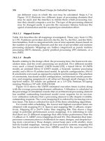
1-3-2 Channel Impulse Response
This scenario can be demonstrated by means of the channel impulse response. Lets assume
that a very short pulse of extremely high amplitude [in the ideal case, a Dirac pulse
δ
(
t
)] is
sent by the transmitting antenna at a time
t
0
= 0. This pulse arrives at the receiving antenna
direct and in the form of reflections with different delays
τ
i
and different amplitudes because
of path losses. The impulse response of the radio channel is the sum of all received pulses
(Figure 1-8). Since the mobile receiver and also some of the reflecting objects are moving,
the channel impulse response is a function of time and of delays
τ
i
; that is, it corresponds to
Figure 1-5
Receive signal as a function of time or position.
Figure 1-6
Rayleigh and Rice distributions.
1-3 THE RADIO CHANNEL AND MODULATION REQUIREMENTS
7