Package Mechanical Drawings ppt
Bạn đang xem bản rút gọn của tài liệu. Xem và tải ngay bản đầy đủ của tài liệu tại đây (6.64 MB, 86 trang )
April 2013 1
© 2013 Microsemi Corporation
Package Mechanical Drawings
Naming Conventions
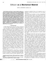
This document lists all package types used for Microsemi FPGAs and provides detailed drawings and dimensions.
Table 1 lists the package types, their acronyms, and the naming convention used when referring to a package of that
type with a particular pin count.
Table 1 • Package Naming Conventions
Package Type Package Name Acronym
Package/Pin Naming
Convention (example)
Ceramic Packages Ceramic Pin Grid Array CPGA PG84
Ceramic Quad Flat Pack CQFP CQ208
Ceramic Chip Carrier Land Grid Substrate CCLG CC256
Ceramic Column Grid Array CCGA CG484
Ceramic Land Grid Array CLGA LG484
Plastic Packages
(leadframe-based, peripheral leads)
Quad Flat No Lead QFN QN48
Plastic Quad Flat Pack PQFP PQ208
Thin Quad Flat Pack TQFP TQ144
Very Thin Quad Flat Pack VQFP VQ176
Plastic Quad Flat Pack (exposed heatsink) RQFP RQ208
Plastic Leaded Chip Carrier PLCC PL44
Plastic Packages
(substrate-based, area array pins)
Plastic Ball Grid Array (1.27 mm pitch) PBGA BG272
Fine Pitch Plastic Ball Grid Array (1.00 mm pitch) FBGA FG144
Chip Scale Package (0.50 mm pitch) CSP CS81
Chip Scale Package (0.80 mm pitch)* CSP CS49
Micro Chip Scale Package UCS UC36
Very Fine Ball Pitch Grid Array VFPBA VF400
Note: *Currently the CS49, CS128, CS180, and CS289 packages are 0.80 mm pitch rather than 0.50 mm pitch.
Revision 44
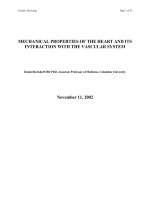
Ceramic Pin Grid Array (CPGA)
2 Revision 44
Ceramic Pin Grid Array (CPGA)
PG84
Notes:
1. All dimensions are in inches unless otherwise stated.
2. BSC = Basic spacing between centers.
Supported Devices
A1010B A1020B
Orientation
Pin
1.100" ± 0.020" square
0.072"
0.088"
0.015"
0.120"
0.140"
0.100" BSC
0.018" ± 0.002"
0.050" ± 0.010"
0.045"
0.055"
L
K
J
H
G
F
E
D
C
B
A
1110987654321
Pin #1 ID
Top View
Bottom View
Side View
1.000" BSC
Package Mechanical Drawings
Revision 44 3
Ceramic Pin Grid Array
PG100
Notes:
1. All dimensions are in inches unless otherwise stated.
2. BSC = Basic spacing between centers.
Supported Devices
A1225XL* A1415A*
Note: *This product is obsolete.
0.015"
Orientation
Pin
1.100" ± 0.015" square
0.072"
0.88"
0.120"
0.140"
0.050" ± 0.010"
Pin #1 ID
0.05"
0.055"
111051
Top View
Bottom View
Side View
0.100" BSC
1.000" BSC
0.01 ± 0.00"
Ceramic Pin Grid Array (CPGA)
4 Revision 44
Ceramic Pin Grid Array
PG132
Notes:
1. All dimensions are in inches unless otherwise stated.
2. BSC = Basic spacing between centers.
Supported Devices
A1240A A1240XL*
Note: *This product is obsolete.
0.015"
Orientation
Pin
0.120"
0.140"
0.100" BSC
0.018" ± 0.002"
0.050" ± 0.010"
1.200" BSC
0.072"
0.088"
Pin #1 ID
0.045"
0.055"
11 12 1310987654321
N
M
L
K
J
H
G
F
E
D
C
B
A
Top View
Bottom View
Side View
1.360" ± 0.015" square
Package Mechanical Drawings
Revision 44 5
Ceramic Pin Grid Array
PG175
Notes:
1. All dimensions are in inches unless otherwise stated.
2. BSC = Basic spacing between centers.
Supported Devices
A1440A*
Note: *This product is obsolete.
Index Mark
0.018" ± 0.002"
0.130" ± 0.010"
0.050" ± 0.005"
0.105" ± 0.010"
1.400" BSC
0.100" BSC
0.05" ± .0005"
1.570" ± 0.015" square
R
P
N
M
L
K
J
H
G
F
E
D
C
B
A
Top View
Bottom View
Side View
123456789101112131415
Ceramic Pin Grid Array (CPGA)
6 Revision 44
Ceramic Pin Grid Array
PG176
Notes:
1. All dimensions are in inches unless otherwise stated.
2. BSC = Basic spacing between centers.
Supported Devices
A1280A A1280XL*
Note: *This product is obsolete.
0.120"
0.140"
0.105" ± 0.010"
0.050" ± 0.005"
1.400" BSC
0.100" BSC
1.570" ± 0.015" square
11 12 13 14 1510987654321
R
P
N
M
L
K
J
H
G
F
E
D
C
B
A
0.018" ± 0.002"
0.05" ± 0.005"
Top View
Bottom View
Side View
Index Mark
Package Mechanical Drawings
Revision 44 7
Ceramic Pin Grid Array
PG207
Notes:
1. All dimensions are in inches unless otherwise stated.
2. BSC = Basic Spacing between Center.
Supported Devices
A1460A
0.100" BSC
0.05" ± 0.005"
0.115" ± 0.011"
11 12 13 14 15 16 1710987654321
U
T
R
P
N
M
L
K
J
H
G
F
E
D
C
B
A
1.600" BSC
0.018" ± 0.002"
0.180" ± 0.010"
0.05" ± 0.005"
Top View
Side View
Bottom View
Index Mark
1.77" ± 0.010" square
Ceramic Pin Grid Array (CPGA)
8 Revision 44
Ceramic Pin Grid Array
PG257
Notes:
1. All dimensions are in inches unless otherwise stated.
2. BSC = Basic spacing between centers.
Supported Devices
A14100A
1.970" ± 0.015" square
0.105" ± 0.012"
0.100" BSC
0.120"
0.140"
0.018" ± 0.002
"
0.05" ± 0.005"
0.005" ± 0.005"
Top View
Bottom View
Side View
A
B
C
D
E
F
G
H
J
K
L
M
N
P
R
T
V
X
Y
1 2 3 4 5 6 7 8 9 10111213141516171819
1.800" ± 0.012
I
ndex Mark
Package Mechanical Drawings
Revision 44 9
Ceramic Quad Flat Pack (CQFP)
CQ84
Notes:
1. Units are mm.
2. LID should be connected to GND.
3. Die attach area should be connected to GND.
Top View
Ceramic Quad Flat Pack (CQFP)
10 Revision 44
Ceramic Quad Flat Pack
CQ84 Side View and Bottom View
Notes:
1. Units are mm.
2. LID should be connected to GND.
3. Die attach area should be connected to GND.
Supported Devices
A1020B RT1020*
A32100DX* RH1020*
A54SX32A RT54SX32S*, RTSX32SU
Note: *This product is obsolete.
Bottom View
Side View
MAX. 2.31
MAX. 2.00
1.77 ± 0.18
2.15 ± 0.25
(2.55)
(0.45)
DEPTH
(2.15)
(2.05)
(2.40)
DEPTH
INDEX MARK
(PLATING OPTION)
84
1
64
64
43
42
21
22
4X
(0.76 × 45º)
CHAMFER
4X
(1.25)
(1.10)
(DEPTH 0.45)
4X
LEAD MATERIAL
Fe-Ni-Co ALLOY
BRAZED
Ag-Cu ALLOY
0.889
4X
24.13 ± 0.25
CERAMIC
Package Mechanical Drawings
Revision 44 11
Plate Thickness
Ni Plating 2.03~8.89 micron
Au Plating 2.54 micron min.
Lid Size A B
A1020B 13.21 13.21
A32100DX* 13.97 13.97
A54SX32A 13.21 13.21
RH1020* 13.21 13.21
RT1020* 13.21 13.21
RT54SX32S*, RTSX32SU 10.54 13.61
Note: *This product is obsolete.
Ceramic Quad Flat Pack (CQFP)
12 Revision 44
Ceramic Quad Flat Pack
CQ132, CQ172, CQ196, CQ208, CQ256 and CQ352—Cavity Up without Heat
Sink
Notes:
1. All dimensions are in inches except CQ208, CQ256, and CQ352, which are in millimeters. Refer to the "CQFP without Heat Sink
Dimensions" section on page 18 for the dimensions.
2. Outside lead frame holes (from dimension H) are circular for the CQ208, CQ256, and CQ352.
3. Seal ring and lid are connected to Ground.
4. Packages are shipped unformed with the ceramic tie bar in a test carrier.
A
b
H
D1
D2
E2 E1
F
L1 K
Ceramic
Tie Bar
Number 1
e
A1
C
Lead Kovar
Lid
Top View
Side View
Package Mechanical Drawings
Revision 44 13
Supported Devices
CQ132 CQ172 CQ196 CQ208 CQ256 CQ352
A1425A
RT1425A
A1280A
RH1280*
RT1280A
A1460A
RT1460A
A42MX36
AX250
AX500
A54SX16
A54SX32
A54SX32A
A54SX72A
APA300
APA600
APA1000
RT54SX32S*
RTSX32SU
RTAX250S
A14100A
AX2000
A54SX32A
A54SX72A
RT14100A
RT54SX32S*
RTSX32SU
RTAX2000S
RT3PE600L
RT3PE3000L
AX250
AX500
AX1000
AX2000
APA300
APA600
APA1000
RTAX250S
RTAX1000S
RTAX2000S
RTAX4000S
RTAX2000D
RTAX4000D
Note: *This product is obsolete.
Ceramic Quad Flat Pack (CQFP)
14 Revision 44
Ceramic Quad Flat Pack
CQ208 and CQ256—Cavity Up with Heat Sink
Notes:
1. All dimensions are in inches except CQ208, CQ256, and CQ352, which are in millimeters. Refer to the "CQFP with Heat Sink
Dimensions" section on page 19 for the dimensions.
2. Outside lead frame holes (from dimension H) are circular for the CQ208, CQ256, and CQ352.
3. Seal ring and lid are connected to Ground.
4. Lead material is Kovar with minimum 60 microinches gold over nickel.
5. Packages are shipped unformed with the ceramic tie bar.
A
b
H
D1
D2
E2 E1
F
L1
K
Ceramic
Tie Bar
Number 1
e
A1
Heat Sink
C
Lead Kovar
Lid
Top View
Side View
Package Mechanical Drawings
Revision 44 15
Supported Devices
CQ208 CQ256
A32200DX*
RT54SX72S*
RTSX72SU
A54SX16
A54SX32
RT54SX72S*
RTSX72SU
Note: *This product is obsolete.
Ceramic Quad Flat Pack (CQFP)
16 Revision 44
CQ256—Cavity Down without Heat Sink
Notes:
1. Dimensions are in millimeters. Refer to the "CQFP with Heat Sink Dimensions" section on page 19 for the dimensions.
2. Seal ring and lid are connected to Ground.
3. Lead material is Kovar with gold plate over nickel.
4. Packages are shipped unformed with the ceramic tie bar.
5. Package is cavity down, with the lid facing the bottom of the package. However, the leads can be formed on either side if the
application requires the lid to be facing the top.
Supported Devices
A42MX36
L1
F
K
e
b
Lid
Lead Material
Fe–Ni–Co Alloy
A
c
A1
Lid E2 E1
1
256
H
D1
D2
Top View
Side View
Package Mechanical Drawings
Revision 44 17
Ceramic Quad Flat Pack
CQ256—Cavity Down with Heat Sink
Notes:
1. Packages are shipped unformed with the ceramic tie bar in a test carrier.
2. Dimensions are in millimeters. Refer to the "CQFP with Heat Sink Dimensions" section on page 19 for the dimensions.
Supported Devices
A32200DX*
Note: *This product is obsolete.
F
eb
Lid
Lead Material
Fe–Ni–Co Alloy
A
c
A1
Heat Sink
Lid
1
Top View
Side View
256
E2 E1
D2
D1
L1
H
K
Ceramic Quad Flat Pack (CQFP)
18 Revision 44
CQFP without Heat Sink Dimensions
JEDEC
Equivalent
CQ132
MO-113 VAR AC
CQ172
MO-113 VAR AE
CQ196
MO-113 VAR AB CQ208
Symbol Min. Nom. Max. Min. Nom. Max. Min. Nom. Max. Min. Nom. Max.
A 0.094 0.105 0.116 0.094 0.105 0.116 0.094 0.105 0.116 2.30 2.80 3.30
A1 0.080 0.090 0.100 0.080 0.090 0.100 0.080 0.090 0.100 2.00 2.30 2.80
b 0.007 0.008 0.010 0.007 0.008 0.010 0.007 0.008 0.010 0.17 0.20 0.22
c 0.004 0.006 0.008 0.004 0.006 0.008 0.004 0.006 0.008 0.11 0.15 0.18
D1/E1 0.940 0.950 0.960 1.168 1.180 1.192 1.336 1.350 1.364 28.96 29.21 29.46
D2/E2 0.800 BSC 1.050 BSC 1.200 BSC 25.5 BSC
e 0.025 BSC 0.025 BSC 0.025 BSC 0.50 BSC
F 0.325 0.350 0.375 0.175 0.200 0.225 0.175 0.200 0.225 7.05 7.75 8.45
H 2.320 BSC 2.320 BSC 2.320 BSC 70.00 BSC
K 2.140 BSC 2.140 BSC 2.140 BSC 65.90 BSC
L1 2.485 2.500 2.505 2.485 2.495 2.505 2.485 2.495 2.505 74.60 75.00 75.40
JEDEC
Equivalent
CQ256
MO-134 VAR AB
CQ352
MO-134 VAR AE
Symbol Min. Nom. Max. Min. Nom. Max.
A 2.302.803.302.432.662.89
A1 2.00 2.30 2.80 2.05 2.28 2.51
b 0.180.200.220.180.200.22
c 0.11 0.15 0.18 0.11 0.15 0.18
D1/E1 35.64 36.00 36.64 47.75 48.00 48.25
D2/E2 31.5 BSC 43.51 BSC
e 0.50 BSC 0.50 BSC
F 7.05 7.75 8.45 5.00
H 70.00 BSC 70.00 BSC
K 65.90 BSC 65.90 BSC
L1 74.60 75.00 75.40 74.60 75.00 75.40
Notes:
1. All dimensions are in inches except CQ208, CQ256, and CQ352, which are in millimeters.
2. BSC = Basic spacing between centers. This is a theoretical true position dimension and so has no tolerance.
Package Mechanical Drawings
Revision 44 19
CQFP with Heat Sink Dimensions
The dimensions above are for reference only. For more accurate dimensions, use the dimensions in the SMD drawings
for a specified device.
For heat sink information, refer to the Hermetic Package Mechanical Configuration document (Cavity, weight, lid size
and heat sink size) located at: www.actel.com/documents/HermeticPckg.pdf
JEDEC Equivalent CQ208
CQ256
MO-134 VAR AB
Symbol Min. Nom. Max. Min. Nom. Max.
A 2.79 3.30 3.90 2.79 3.30 3.90
A1 2.00 2.30 2.80 2.00 2.30 2.80
b 0.18 0.20 0.22 0.18 0.20 0.22
c 0.11 0.15 0.17 0.11 0.15 0.18
D1/E1 28.96 29.21 29.46 35.64 36.00 36.66
D2/E2 25.5 BSC 31.5 BSC
e 0.50 BSC 0.50 BSC
F 7.05 7.75 8.45 7.05 7.75 8.45
H 70.00 BSC 70.00 BSC
K 65.90 BSC 65.90 BSC
L1 74.60 75.00 75.40 74.60 75.00 75.40
Notes:
1. All dimensions are in inches except CQ208, CQ256 and CQ352, which is in millimeters.
2. BSC = Basic spacing between centers. This is a theoretical true position dimension and so has no tolerance.
Ceramic Chip Carrier Land Grid Substrate (CCLG)
20 Revision 44
Ceramic Chip Carrier Land Grid Substrate (CCLG)
CC256
Note: Units are mm.
Supported Devices
RT54SX32S*
RTSX32SU
Note: *This product is obsolete.
(1.000X45°)
CHAMFER
External Bonding Pad 1
256
Top View
(see next page for clear dimension)
17.000±0.203
LID 12.954±0.152
6.001
6.140
192
193
TYP.
(R 0.254)
A1 Index Corner
(0.500X45°)
CHAMFER
LID 15.240±0.152
6.140
6.001
6.140
6.001
4X
0.254
3X
R 0.500
129
64
TYP.
TYP.
(0.127)
(0.762)
128
65
0.114 TYP.
0.076 TYP.
4X
(0.1651)
4X
(0.0953)
6.001
6.140
4X
(13.70)
123 54 6 7 8 9 10111213141516
1.000
15.000
Ø0.600±0.050
256X
T
R
P
N
M
L
K
J
H
G
F
E
D
C
B
A
1.000
15.000
Bottom View
Detail A
Side View
(with partial section view)
LID
A
1.397±0.140
0.508±0.051
0.254±0.025
0.889±0.051
(bottom to External Bonding pads)
4X
(0.250X45
o
)
Chamfer
Package Mechanical Drawings
Revision 44 21
CCLG Substrate Dimensions
External Bonding Pad 1
Top View (Zoom 2.4x)
17.000±0.203
LID 12.954±0.152
6.001 6.140
192
193
256
TYP.
(R 0.254)
A1 Index Corner
(1.000X45°)
CHAMFER
(0.500X45°)
CHAMFER
LID 15.240±0.152
6.140
6.001
6.140
6.001
4X 0.254
3X
R 0.500
129
64
TYP.
TYP.
(0.127)
(0.762)
128
65
0.114 TYP.
0.076 TYP.
4X
(0.1651)
4X
(0.0953)
6.001
6.140
4X
(13.70)
Ceramic Column Grid Array (CCGA)
22 Revision 44
Ceramic Column Grid Array (CCGA)
CG484
Note: The top and side views will be completed in the future.
Supported Devices
RT3PE600L
RT3PE3000L
CCGA
Side View
A1 Corner
Index Area
A2
A1
b
E
CLGA
Side View
A2
Top View
Bottom View
D
A
A
AB
AA
Y
W
V
U
T
R
P
N
M
L
K
J
H
G
F
E
D
C
B
A
1
234
5
67 8
9
10 1112
13
14 15 16
17
18 19 20
21
22
e
e
E1
D1
Package Mechanical Drawings
Revision 44 23
Ceramic Column Grid Array
CG624
Supported Devices
AX1000
AX2000
RTAX1000S
RTAX2000S
RTAX250S
APA600
APA1000
RTSX72SU
CCGA
Side View
e
AE
AD
AC
AB
AA
Y
W
V
U
T
R
P
N
M
L
K
J
H
G
F
E
D
C
B
A
1
234
5
67 8
9
10 1112
13
14 15 16
17
18 19 20
21
22 23 2524
e
A1 Corner
Index Area
A2
A1
b
E1
E
CLGA
Side View
A2
Top View
Bottom View
D1
D
A
A
Ceramic Column Grid Array (CCGA)
24 Revision 44
Ceramic Column Grid Array
CG896
Supported Devices
RT3PE3000L
D1
e
Top View
D
A
A1 Corner
Index Area
E
CCGA
Side View
CLGA
Side View
Bottom View
E1
e
A
B
C
D
E
F
G
H
J
K
L
M
N
P
R
T
U
V
W
Y
AA
AB
AC
AD
AE
AF
AG
AH
AJ
AK
1 2 3 4 5 6 7 8 910111213141516171819202122232425262728
30
29
A
A2
A2
A1
b
Package Mechanical Drawings
Revision 44 25
CCGA Dimensions
Dimension
CG484 CG624 CG896
Min. Nom. Max. Min. Nom. Max. Min. Nom. Max.
CCGA - A 5.19 5.72 6.19 4.54 4.88 5.41 5.65 6.23 6.75
CLGA - A 3.06 3.51 3.83 2.41 2.67 3.05 3.16 3.51 3.86
A1 2.15 2.21 2.36 2.15 2.21 2.36 2.15 2.21 2.36
A2 2.70 3.00 3.30 2.06 2.29 2.52 3.16 3.51 3.86
b 0.43 0.51 0.59 0.43 0.51 0.59 0.43 0.51 0.59
D 22.77 23.00 23.23 32.17 32.50 32.83 30.69 31.00 31.31
D1 21.00 BSC 30.48 BSC 29.00 BSC
E 22.77 23.00 23.23 32.17 32.50 32.83 30.69 31.00 31.31
E1 21.00 BSC 30.48 BSC 29.00 BSC
e 1.00 BSC 1.27 BSC 1.00 BSC