Construction Stage Analysis of Prestressed Concrete Box Bridge using General Funtions potx
Bạn đang xem bản rút gọn của tài liệu. Xem và tải ngay bản đầy đủ của tài liệu tại đây (3.78 MB, 53 trang )
CONTENTS
Construction sequence and construction stage analysis for FCM
1
Assign Working Environment
3
Define material and section properties
4
Structural Modeling
13
Pier Modeling
19
Structure Group
20
Define the boundary group and input boundary conditions 24
Assign Load Group
Define and Arrange Construction Stage
27
29
Define Construction Stage
29
Construction Stage arrangement
34
Load input
37
Performing Structural Aanlysis
51
Construction Stage Analysis of Prestressed Concrete Box Bridge (FCM) using General Functions
In this tutorial the sequence analysis for construction stage analysis is outlined. The
example selected is a prestressed concrete box girder bridge (FCM) and the construction
stage analysis is performed using the Wizard”.
Substructure construction
Form traveler assembly
Substructure completion
Pier table construction and fixity device set
Set the form traveler on the pier table
Form work assembly, reinforcement bar
and tendon placing (7 days)
Pour concrete, curing concrete, and jack
tendons (5 days)
Move Form traveler to next segment
Side span construction (FSM)
Key segment construction
Set bearings, then jacking bottom tendon
Pave structure
Finishing
※ This bridge example is a 3 span bridge and total 4 form traveler is assumed.
1
ADVANCED APPLICATIONS
In the construction stage analysis the above construction sequences should be
considered precisely. The construction stage analysis capability of MIDAS/Civil
comprises an activate/deactivate concept of Structure Groups, Boundary Groups, and
Load Groups. The analysis sequence of construction stage analysis for FCM is as
follows:
1.
Define material and section
2.
Structure modeling
3.
Define Structure Group
4.
Define Boundary Group
5.
Define Load Group
6.
Input Load
7.
Arrange tendons
8.
Prestress tendons
9.
Define time dependent material property
10. Perform structural analysis
11. Review results
In the above steps (from step 2 to 8) are explained in “Construction stage analysis of
prestressed concrete box bridge (FCM) using the Wizard”. In this tutorial, the
procedure to analysis a FCM bridge steps 1 to 8 using general functions will be explained.
The procedures for steps 9 to 11 is identical with those for the “Construction stage
analysis of prestressed concrete box bridge (FCM) using the Wizard”, and will not be
repeated in this tutorial.
2
Construction Stage Analysis of Prestressed Concrete Box Bridge (FCM) using General Functions
To perform a construction stage analysis for a FCM, open a new file (
and save(
New Project)
Save) as ‘fcm.mcb’.
Assign the unit system as ‘kN’ and ‘m’. The unit system can be changed arbitrary during
modeling at user’s convenience.
File /
The unit system
selected
can
be
changed by clicking
on the unit selection
button on the Status
Bar located at the
bottom of screen.
New Project
File /
Save (FCM)
Tools / Unit System
Length> m ;
Force>kN ↵
Figure 1 Assign unit system
3
ADVANCED APPLICATIONS
Define material properties for the girder, pier, and tendons.
Model / Properties /
Material
Type>Concrete ; Standard>ASTM (RC)
DB>Grade C5000 ↵
Type>Concrete ; Standard> ASTM (RC)
DB>Grade C4000 ↵
Name>Tendon
; Type>User Defined
Modulus of Elasticity (2.0e8)
Thermal Coefficient (1.0e-5)
↵
Figure 2 Material Data input dialog box
4
Construction Stage Analysis of Prestressed Concrete Box Bridge (FCM) using General Functions
Define Creep and Shrinkage data for the girder and pier.
Model / Properties /
Name (C5000)
Time Dependent Material(Creep & Shrinkage)
;
Code>CEB-FIP
Compressive strength of concrete at the age of 28 days (35000)
Relative Humidity of ambient environment (40 ~ 99) (70)
Notational size of member (1)
Type of cement>Normal or rapid hardening cement (N, R)
Age of concrete at the beginning of shrinkage (3) ↵
Model / Properties /
Name (C4000)
Time Dependent Material(Creep & Shrinkage)
;
Code>CEB-FIP
Compressive strength of concrete at the age of 28 days (28000)
Relative Humidity of ambient environment (40 ~ 99) (70)
Notational size of member (1)
Type of cement>Normal or rapid hardening cement (N, R)
Age of concrete at the beginning of shrinkage (3) ↵
Figure 3 Creep and Shrinkage Data
5
ADVANCED APPLICATIONS
Define Compressive Strength data for the girder and pier.
Model / Properties /
Name (C5000)
Time Dependent Material(Comp. Strength)
;
Type>Code
Development of Strength>Code>CEB-FIP
Concrete Compressive Strength at 28 Days (S28) (35000)
Cement Type(a) (N, R : 0.25)
Model / Properties /
Name (C4000)
↵
Time Dependent Material(Comp. Strength)
;
Type>Code
Development of Strength>Code>CEB-FIP
Concrete Compressive Strength at 28 Days (S28) (28000)
Cement Type(a) (N, R : 0.25)
Figure 4 Compressive Strength Data
6
↵
Construction Stage Analysis of Prestressed Concrete Box Bridge (FCM) using General Functions
Assign Time Dependent Materials to material data.
Model / Properties /
Time Dependent Material Link
Time Dependent Material Type
Creep/Shrinkage>C5000
Comp. Strength>C5000
Select Material for Assign>Materials>
1: Grade C5000
Selected Materials
Time Dependent Material Type
Creep/Shrinkage>C4000
Comp. Strength>C4000
Select Material for Assign>Materials>
2: Grade C4000
Selected Materials
↵
Figure 5 Time Dependent Material Link window
7
ADVANCED APPLICATIONS
Assign the notational size of members automatically.
Model / Properties /
Change Element Dependent Material Property
Select all
Option>Add/Replace
Element Dependent Material
Notational Size of Member>Auto Calculate ↵
Figure 6 Change Element Dependent Material Property Window
8
Construction Stage Analysis of Prestressed Concrete Box Bridge (FCM) using General Functions
First, define the pier section by User Type and then define the box section. Using the
Tapered Section Group function, section properties for a variable section range can
easily be calculated using the definition of a variable section range, by Group, together
with the input of the dimensions at both ends. When using the Tapered Section Group
function, it is unnecessary to define all the dimensions for each segment, only the section
properties for pier and center span components are needed.
First, define pier section.
Model / Properties /
Section
DB/User tab
Section ID (1) ; Name (Pier)
Section Shape>Solid Rectangle ;
User>H (1.8), B(8.1) ↵
Figure 7 Set Section dialog box
9
ADVANCED APPLICATIONS
Define the section properties for the center span section.
Section
Model / Properties /
PSC tab
Section ID (2) ; Name (Span)
Section Type>1 Cell
Joint On/Off>JO1 (on) ,
JI1 (on),
Outer
HO1 (0.25)
BO1 (2.8)
;
;
HO3 (2.1)
BO1-1 (1.05)
;
HO2 (0.35)
;
BO3 (3.55)
Inner
HI1 (0.275)
HI4 (0.25) ;
;
HI2 (0.325) ;
BI3-1 (1.85)
↵
1.350
1.050
1.750
2.800
450 1.250
250
260
2.100
3.100
1.590
325
275
1.750
250
350
450
BI1-1 (1.35)
BI3 (3.1) ;
1.750
HI3 (1.59)
HI5 (0.26)
BI1 (3.1) ;
1.050
JI5 (on)
Offset>Center-Top
Define the section
from
Center/Top
because sections are
variable
and
the
section shapes are
not uniform.
1.850
3.550
Figure 8 Defined Center Span Section
10
Construction Stage Analysis of Prestressed Concrete Box Bridge (FCM) using General Functions
Define the box section at the supports.
Model / Properties /
Section
PSC tab
Section ID (3) ; Name (Support)
Section Type>1 Cell
Joint On/Off>JO1 (on) ,
JI1 (on),
JI5 (on)
Offset>Center-Top
Outer
HO1 (0.25)
BO1 (2.8)
;
HO2 (0.35)
;
HO3 (6.4)
BO1-1 (1.05)
;
;
BO3 (3.55)
HI2 (0.325)
;
HI3 (5.3)
Inner
HI1 (0.275)
HI4 (0.25) ;
;
HI5 (0.85)
BI1 (3.1) ;
BI3 (3.1) ;
450
1.750
BI3-1 (1.85)
↵
1.350
1.050
1.750
2.800
450 1.250
250
850
6.400
3.100
5.300
325
275
1.750
250
350
1.050
BI1-1 (1.35)
1.850
3.550
Figure 9 Defined Box Section at Supports
11
ADVANCED APPLICATIONS
After completion of section property input, generate the section properties for the
To generate a
Tapered
Section
Group using Tapered
Type
sections,
predefine
Tapered
Type sections.
Tapered Type using section No. 2 and No. 3.
Model / Properties /
Section
Tapered tab
Section ID (4) ; Name (Span-Support)
Section Type>PSC-1 Cell ;
Joint On/Off>JO1 (on)
Size-I>
Each segment is
designed as a liner
tapered
member
because it is difficult
to make a curved
formwork. Define the
section
changes
within
a
tapered
segment as liner, and
model each segment
as one element.
(Span)
Size-J>
(Support)
y Axis Variation>Linear ;
z Axis Variation>Linear
Offset>Center-Top
Section ID (5) ; Name (Support-Span)
Section Type>PSC-1 Cell ;
Joint On/Off>JO1 (on)
Size-I>
(Support)
Size-J>
(Span)
y Axis Variation>Linear ;
z Axis Variation>Linear
Offset>Center-Top ↵
Figure 10 Tapered Section
12
Construction Stage Analysis of Prestressed Concrete Box Bridge (FCM) using General Functions
Model FCM Bridge using general functions in MIDAS/CIVIL.
To perform construction stage analysis, construction stages must first be defined. In
MIDAS/CIVIL, there are two working modes, Base Stage mode and Construction Stage
mode.
In Base Stage mode, any structural model, load conditions, and boundary conditions can
be defined, but the real analysis is not performed. In Construction Stage, the structural
analysis is performed, but the structural model input data cannot be changed, modified,
or deleted except for the boundary conditions and load conditions.
Construction Stages do not comprise of individual elements, boundary conditions, or
load conditions, but comprise of Activation and Deactivation commands for the
Structure Group, Boundary Group, and Load Group. Within the Construction Stage
mode, the boundary conditions and load conditions included in the activated Boundary
Group and Load Group can be modified or deleted.
In the analysis of FCM bridge, the loads that are applied during construction (prestress
of tendons, form traveler, and self-weight of the segment) are complicated, and so the
construction stages are predefined and then the load condition is defined in each
construction stage. The structural systems and boundary conditions are defined in Base
Stage mode.
The modeling procedure is as follows:
1.
Prestessed concrete box girder modeling
2.
Pier modeling
3.
Define Time Dependent Material Property
4.
Assign Structure Group
5.
Assign Boundary Group and input boundary condition
6.
Assign Load group
13
ADVANCED APPLICATIONS
Model the prestressed concrete box Girder Bridge.
Model one segment as one beam
element and divide the pier table at the intersection of the pier and at the center
location. In the FSM Bridge, divide at the location of the bottom tendon anchorage.
85.000
2.000
4 @ 4.250 = 17.000
12 @ 4.750 = 57.000
2.000
4.000 3.000
Pier 주두부
Table
12
11
9
10
7
8
6
5
2
3
4
1
Key Seg 1
P1
FSM구간
FSM
Segment 1
2.100
130.000
65.000
65.000
12 @ 4.750 = 57.000
3.000 4.000
4.000 3.000
12 @ 4.750 = 57.000
1.000
1.000
C
L
Pier Table
주두부
주두부
Pier Table
13
14
15
16
17
18
19
21
20
22
23
24
24
23
22
21
20
19
18
17
16
15
14
13
Key Seg 2
P2
P1
Segment 2
Segment 2
2.100
2.100
85.000
12 @ 4.750 = 57.000
3.000 4.000
2.000
4 @ 4.250 = 17.000
주두부
Pier Table
1
2
3
4
5
6
7
8
9
10
11
12
Key Seg 3
P2
Segment 1
FSM구간
FSM
2.100
Figure 11 Segment Division
14
2.000
Construction Stage Analysis of Prestressed Concrete Box Bridge (FCM) using General Functions
First generate nodes, and then model right side of the prestressed concrete box girder
using the Extrude Element function(
Front View,
Auto Fitting (on),
Line Grid Snap (off),
Model / Nodes /
Extrude Elements).
Point Grid Snap (off)
Node Snap (on),
Element Snap (on)
Create Nodes
Coordinate (x, y, z) ( 0, 0, 0 ) ↵
Model / Elements /
Extrude Elements
Select All
Extrude Type>Node → Line Element
Element Type>Beam ;
Section>2: Span
;
Material>1: Grade C5000
Generation Type>Translate
Translation>Unequal Distance ;
Axis>x
Distances ( 2@1, , 2@1, , 4, , ,
, 4, , 1 ) ↵
Figure 12 Right half of the beam element generation
15
ADVANCED APPLICATIONS
Symmetrically copy the elements generated for the right half of the beam using the
Mirror Element function(
Mirror Elements).
Select Reverse Element Local to
coincide with the element local axis for the left half elements generated by symmetric
copy with the elements on the right half.
Model / Elements /
Mirror Elements
Select all
Mode>Copy ;
Reflection>y-z plane x : ( 150 )
Reverse Element Local (on) ↵
(150)
Figure 13 Symmetric copy of the beam element
16
Construction Stage Analysis of Prestressed Concrete Box Bridge (FCM) using General Functions
Change section properties for the tapered and pier top elements using Select Identify
Element(
Select Identity-Elements) and Works Tree functions. Segment twelve, which
is connected to the key segment, is constructed as a uniform section to coincide with the
formwork of the key segment. Change segment one to eleven and the end portions of
the pier top elements to a tapered section. The section transformed from span
components to support components is changed. Both span-support section and the
section transformed from support components to span components are changed to
support-span section. Change the section in pier table to support section.
Tree Menu>Works tab
Select Identity-Elements ( 10 to 21, 69 to 80 )
EntterrrKey
En te Key
En e Key
Works>Properties>Section>4: Span-Support Drag&Drop
Select Identity-Elements ( 28 to 39, 51 to 62 )
Works>Properties>Section>5: Support-Span
Select Identity-Elements ( 22 to 27, 63 to 68 )
EntterrrKey
En te Key
En e Key
Drag&Drop
EntterrrKey
En te Key
En e Key
Works>Properties>Section>3: Support Drag&Drop
Drag & Drop
Figure 14 Section change
17
ADVANCED APPLICATIONS
Assign beam elements in tapered members to variable section group by Tapered Section
Section properties
for
the
tapered
members can be
automatically
calculated from the
defined
section
properties at each
end of the tapered
section by assigning
a Tapered Section
Group.
Group function(
Tapered Section Group).
Model / Properties /
Tapered Section Group
Group Name (1stspan)
; Element List ( 10 to 21 )
Section Shape Variation>z-Axis>Polynomial ( 2.0)
Symmetric Plane>From>i
Group Name (2ndspan1)
; Distance ( 0 )
; Element List ( 28 to 39 )
Section Shape Variation>z-Axis>Polynomial ( 2.0)
Symmetric Plane>From>j
; Distance ( 0 )
Select Polynomial
and 2.0 because the
section
height
changes
in
a
parabolic form.
Group Name (2ndspan2)
In Tapered Section
Group, the parabola
function
is
determined uniquely
by
the
defined
coordinates of two
points
on
the
parabola and at the
center point. Because
the j end of segment
twelve is the center
point of the parabola,
select i end and input
a zero distance.
Section Shape Variation>z-Axis>Polynomial ( 2.0)
; Element List ( 69 to 80 )
Section Shape Variation>z-Axis>Polynomial ( 2.0)
Symmetric Plane>From>i
Group Name (3rdspan)
Symmetric Plane>From> j
Iso View,
; Distance ( 0 )
; Element List ( 51 to 62 )
; Distance ( 0 )
Hidden (on)
Figure 15 Assign tapered section group
18
Construction Stage Analysis of Prestressed Concrete Box Bridge (FCM) using General Functions
After copying the nodes of the prestessed concrete box girder, model the pier using the
Extrude Element function(
Extrude Elements). To model the 60m pier, divide the pier
length into six equal length elements.
Hidden (off),
Model / Nodes /
Front View
Translate Nodes
Select Identity-Nodes ( 23, 27, 65, 69 )
EntterrrKey
En te Key
En e Key
Mode>Copy ; Translation>Equal Distance
Because
the
upper center point of
the box section is
used as the base of
the box girder model,
copy the nodes to a
distance of –7m (total
height of support
section) in the Zdirection.
dx, dy, dz ( 0, 0, -7 )
Model / Elements /
; Number of Times ( 1 )
↵
Extrude Elements
Select Recent Entities
Extrude Type>Node → Line Element
Element Type>Beam ;
Section>1: Pier ;
Material>2: Grade C4000
Generation Type>Translate
Translation>Equal Distance
dx, dy, dz ( 0, 0, -40/6 ) ; Number of Times ( 6 )
↵
Figure 16 Generate a pier
19
ADVANCED APPLICATIONS
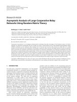
Figure 17 shows the construction sequence and expected duration for each construction
stage. According to the figure, there is a 60-day difference in construction schedule
between Pier 1 and 2. Hence, there will also be a 60-day difference between both
elements when the key segment is being constructed.
Increase
the
element age of some
elements by Time
Load
using
the
Construction Stage
function. A detail
explanation can be
found
in
Time
Dependent AnalysisDefine
and
Constitution
of
Construction Stage in
the Analysis of Civil
Structures manual.
It will be assumed that both piers are constructed at the same time and both cantilevers
are constructed through the same stages before the key segment construction. And just
before the key segment construction, the age of one cantilever will be increased.
Define the elements constructed at the same time as each group by defining Structure
Group because the generation and deletion of elements will be defined using the
activation and deactivation command in Construction Stage function.
A1
P1
P2
12
11
10
9
8
7
6
5
4
3
2
1
A2
C
L
OF PIER
C
L
OF PIER
1
3
2
4
5
6
7
8
9
18
10
11
12
12
11
10
9
8
7
6
5
4
3
2
1
1
2
3
4
5
6
7
8
9
10
11
12
KEY-SEGMENT
17
KEY-SEGMENT
16
15
KEY-SEGMENT
FSM PART
14
SEG (12DAY/SEG)
13
SEG (12DAY/SEG)
FSM PART
12
11
SEG (12DAY/SEG)
SEG (12DAY/SEG)
F/T SETTING
10
9
8
PIER TABLE
F/T SETTING
PIER TABLE
7
PIER
6
5
4
PIER
FOOTING
3
2
1
FOOTING
Figure 17 Construction sequence
20
Construction Stage Analysis of Prestressed Concrete Box Bridge (FCM) using General Functions
Generate Structure Group.
Group
Model / Group / Structure Group / Define Structure Group
By input numbers
to suffix, multiple
Structure Groups can
be
generated
simultaneously.
Name ( Pier ) ;
Suffix ( 1to2 )
Name ( PierTable ) ;
Suffix ( 1to2 )
Name ( P1Seg ) ;
Suffix ( 1to12 )
Name ( P2Seg ) ;
Suffix ( 1to12 )
Name ( KeySeg )
;
Suffix ( 1to3 )
Name ( FSM ) ; Suffix ( 1to2 )
Generated
Structure Group can
be confirmed using
the Group Tab, Tree
Menu.
Figure 18 Element Group Generation
21
ADVANCED APPLICATIONS
Assign beam element to Structure Group using Select Identity-Element(
Select
Identity-Elements) and the Works Tree functions. Group arrangement with confirming
already arranged groups could be performed if the pre-arranged Structure Group is
deactivated.
Tree Menu>Group tab
Select Identity-Elements ( 83to103by4 84to104by4 )
EntterrrKey
En te Key
En e Key
Group>Structure Group>Pier1 Drag&Drop
Select Identity-Elements ( 85to105by4 86to106by4 )
Group>Structure Group>Pier2 Drag&Drop
Select Identity-Elements ( 21to28 )
EntterrrKey
En te Key
En e Key
Group>Structure Group>PierTable1 Drag&Drop
Select Identity-Elements ( 62to69 )
EntterrrKey
En te Key
En e Key
Group>Structure Group>PierTable2 Drag&Drop
Drag & Drop
Figure 19 Structure Group arrangement
22
EntterrrKey
En te Key
En e Key
Construction Stage Analysis of Prestressed Concrete Box Bridge (FCM) using General Functions
Assign corresponding beam elements to the other remaining Structure Groups referring
to next table.
Table 1 Element group arrangement
Element Group
Element Number
Element Group
Element Number
P1Seg1
20, 29
P2Seg4
58, 73
P1Seg2
19, 30
P2Seg5
57, 74
P1Seg3
18, 31
P2Seg6
56, 75
P1Seg4
17, 32
P2Seg7
55, 76
P1Seg5
16, 33
P2Seg8
54, 77
P1Seg6
15, 34
P2Seg9
53, 78
P1Seg7
14, 35
P2Seg10
52, 79
P1Seg8
13, 36
P2Seg11
51, 80
P1Seg9
12, 37
P2Seg12
50, 81
P1Seg10
11, 38
KeySeg1
7, 8
P1Seg11
10, 39
KeySeg2
41, 82
P1Seg12
9, 40
KeySeg3
48, 49
P2Seg1
61, 70
FSM1
1~6
P2Seg2
60, 71
FSM2
42~47
P2Seg3
59, 72
23