API 6d 2008 specification for pipeline valves (gate, ball, and check valves)
Bạn đang xem bản rút gọn của tài liệu. Xem và tải ngay bản đầy đủ của tài liệu tại đây (4.97 MB, 106 trang )
By Authority Of
THE UNITED STATES OF AMERICA
Legally Binding Document
By the Authority Vested By Part 5 of the United States Code § 552(a) and
Part 1 of the Code of Regulations § 51 the attached document has been duly
INCORPORATED BY REFERENCE and shall be considered legally
binding upon all citizens and residents of the United States of America.
HEED THIS NOTICE
: Criminal penalties may apply for noncompliance.
Official Incorporator:
T
HE EXECUTIVE DIRECTOR
OFFICE OF THE FEDERAL REGISTER
WASHINGTON, D.C.
Document Name:
CFR Section(s):
Standards Body:
e
API 6D: Specification for Pipeline Valves
49 CFR 195.116(d)
American Petroleum InstituteSpecification
for
Pipeline Valves
ANSI/API SPECIFICATION
60
TWENTY-THIRD EDITION, APRIL 2008
EFFECTIVE
DATE: OCTOBER
1,
2008
ERRATA
1,
JUNE 2008
ERRATA
2,
NOVEMBER 2008
ERRATA
3,
FEBRUARY 2009
ERRATA
4,
APRIL 2010
ERRATA
5,
NOVEMBER 2010
ERRATA
6,
AUGUST
2011
ADDENDUM
1,
OCTOBER 2009
ADDENDUM
2,
AUGUST
2011
CONTAINS API MONOGRAM
ANNEX
AS
PART OF
U.S. NATIONAL ADOPTION
ISO 14313:2007 (Identical), Petroleum and natural
gas
industries-Pipeline
transportation
systems-
Pipeline valves
AMERICAN
PETROLEUM
INSTITUTE
for
Pipeline Valves
Upstream Segment
ANSI/API SPECIFICATION 6D
lWENTY-THIRD
EDITION, APRIL 2008
EFFECTIVE
DATE: OCTOBER
1,
2008
ERRATA
1,
JUNE 2008
ERRATA
2,
NOVEMBER 2008
ERRATA
3,
FEBRUARY 2009
ERRATA
4,
APRIL 2010
ERRATA
5,
NOVEMBER 2010
ERRATA
6,
AUGUST
2011
ADDENDUM
1,
OCTOBER 2009
ADDENDUM
2,
AUGUST
2011
CONTAINS API MONOGRAM ANNEX AS PART OF
U.S. NATIONAL ADOPTION
ISO 14313:2007 (Identical), Petroleum and natural
gas
industries-Pipeline
transportation
systems-Pipeline
valves
_.
__
._-_
fl.
AMERICAN
PETROLEUM
INSTITUTE
API Foreword
Nothing contained
in
any API publication is to
be
construed as granting any right,
by
implication
or otherwise, for the manufacture,
sale, or use of any method, apparatus, or product covered
by
letters patent. Neither should anything contained
in
the publication be construed as insuring
anyone against
liability for infringement of letters patent.
This document was produced under
API
standardization procedures that ensure appropriate
notification and participation
in
the developmental process and
is
designated as
an
API
standard. Questions concerning the interpretation of the content of this publication or comments
and questions concerning the procedures under which this publication was developed should be
directed
in
writing to the Director of Standards, American Petroleum Institute, 1220 L Street,
N.W., Washington,
D.C. 20005. Requests for permission to reproduce or translate all or any part
of the material published herein should
also
be
addressed to the director.
Generally,
API
standards are reviewed and revised, reaffirmed, or withdrawn at least every five
years. A one-time extension of up to two years may be added to this review cycle. Status of the
publication can
be
ascertained from the API Standards Department, telephone (202) 682-8000.
A catalog of API publications and materials
is
published annually and updated quarterly by API,
1220
L Street, N.W., Washington, D.C. 20005.
Suggested revisions are invited and should
be
submitted to the Standards and Publications
Department,
API, 1220 L Street,
NW,
Washington,
DC
20005,
Shall: As used
in
a standard, "shall" denotes a minimum requirement
in
order to conform
to
the
specification.
Should: As used
in
a standard, "should" denotes a recommendation or that which is advised but
not required
in
order to conform to the specification.
This standard is under the jurisdiction of the
API Standards Subcommittee
on
Valves and
Wellhead Equipment (API SC6). This API standard is identical with the English version of ISO
14313:2007. ISO
14313 was prepared by Technical Committee ISOITC 67 Materials, equipment
and offshore structures for petroleum and natural gas industries,
SC
2,
Pipeline transportation
systems.
For the purposes of this standard, the
following editorial change has been made:
- A national informative annex (Annex
F-API
Monogram) has been included giving guidance
to users.
This standard
shall become effective
on
the date printed
on
the cover but may be used
voluntarily from the date of distribution.
Contents
Page
API Foreword ii
Foreword v
Introduction
vi
1 Scope 1
2 Conformance 1
2.1
Units
of
measurement 1
2.2 Rounding 1
2.3
Compliance
to
standard 1
3 Normative references 2
4 Terms and
definitions
4
5
Symbols
and abbreviated terms 7
5.1
Symbols
7
5.2 Abbreviated terms 7
6
Valve
types
and
configurations
8
6.1
Valve
types
8
6.2
Valve
configurations
9
7 Design
23
7.1
Design
standards
and calculations
23
7.2 Pressure and temperature rating
24
7.3 Sizes 24
7.4 Face-to-face and
end-to-end
dimensions
25
7.5 Valve operation 39
7.6 Pigging
40
7.7 Valve
ends
40
7.8 Pressure relief
41
7.9 Bypasses,
drains
and vents
42
7.10 Injection
points
42
7.11
Drain, vent and sealant lines 42
7.12 Drain,
vent
and sealant valves
43
7.13 Hand-wheels and wrenches - Levers
43
7.14
Locking
devices
43
7.15 Position
of
the
obturator
43
7.16 Position
indicators
43
7.17 Travel
stops
44
7 .18 Actuator, operators and stem extensions 44
7.19 Lifting 44
7.20 Drive
trains
44
7.21
Stem retention 45
7.22 Fire type-testing 45
7.23 Anti-static device 45
7.24 Design
documents
45
7.25 Design
document
review 45
8 Materials 46
8.1
Material specification
46
8.2 Service
compatibility
46
8.3 Forged parts
46
8.4
Composition
limits
46
8.5 Toughness
test
requirements 47
8.6
Bolting
48
8.7
Sour
service 48
8.8 Vent and drain connections
48
9 Welding 48
9.1
Qualifications 48
9.2
Impact
testing 48
9.3 Hardness
testing
49
9.4 Repair 49
10 Quality
control
51
10.1
NDE requirements
51
10.2 Measuring and
test
equipment
51
10.3 Qualification
of
inspection and
test
personnel
51
10.4 NDE
of
repairs 52
10.5 Weld end NDE 52
10.6 Visual
inspection
of
castings
52
11
Pressure testing 52
11.1
General 52
11.2
Stem backseat
test
53
11.3
Hydrostatic
shell
test
53
11.4
Hydrostatic
seat
test
54
11.5 Testing
of
drain,
vent
and sealant injection lines
55
11.6 Draining 55
12 Coating 55
13 Marking
56
14 Preparation
for
shipment
58
15 Documentation 58
Annex A (normative) Requirements
for
non-destructive examination
59
Annex
B (normative) Supplementary
test
requirements 63
Annex
C (informative) Supplementary documentation requirements
67
Annex
D (informative) Purchasing guidelines 68
Annex
E (informative) Marking example 75
Annex
F (informative) API Monogram 77
Bibliography
79
API Specification 6D / ISO 14313
Foreword
ISO (the International Organization for Standardization)
is
a worldwide federation of national standards bodies
(ISO member bodies). The work of preparing International Standards
is
normally carried out through ISO
technical
committees. Each member body interested
in
a subject for which a technical committee has been
established has the right to
be
represented
on
that committee. International organizations, governmental and
non-governmental,
in
liaison with
ISO,
also take part
in
the work. ISO collaborates closely with the
International Electrotechnical Commission (IEC)
on
all matters of electrotechnical standardization.
International Standards are drafted
in
accordance with the rules given
in
the ISO/IEC Directives, Part
2.
The main task of technical committees
is
to
prepare International Standards. Draft International Standards
adopted by the technical committees are circulated
to
the member bodies for voting. Publication
as
an
International Standard requires approval by at least
75
% of the member bodies casting a vote.
Attention
is
drawn to the possibility that some of the elements of this document may
be
the subject of patent
rights.
ISO shall not
be
held responsible for identifying any or all such patent rights.
ISO 14313 was prepared by Technical Committee ISO/TC
67,
Materials, equipment and offshore structures
for petroleum, petrochemical and natural gas industries,
Subcommittee
SC
2,
Pipeline transportation systems.
This second edition cancels and replaces the first edition (ISO 14313:1999), which has been technically
revised, principally by the following.
Clause
2,
on
the requirements for conformity to this International Standard, has been added for
clarification.
Clause
7,
on
the requirements for allowable stresses and allowable deflection
on
design, has been
revised and
clarified.
Clause
8,
on
material, has been revised
to
align the requirements with global industry practice for carbon
content and carbon
equivalent for pressure-containing, pressure-controlling, welding ends and parts
requiring
welding.
New requirements
on
repairs and NDE of welding repairs have been added to Clause 9
on
Welding.
A new table (Table D.2) has been added to Annex D (informative)
to
provide more guidance for those
requirements
listed
in
the text as requiring agreement between the manufacturer/purchaser.
v
API
Specification
60
/ ISO 14313
Introduction
This International Standard
is
the result of harmonizing the requirements of ISO 14313:1999 and
API
Spec 60-2002[5].
The revision of ISO 14313
is
developed based
on
input from both ISO/TC67/SC2 WG2 and
API
60
TG
technical experts. The technical revisions have been made
In
order to accommodate the needs of
industry and to move this
I nternational Standard to a higher level of service
to
the petroleum and natural gas
industry.
Users of this
International Standard should
be
aware that further or differing requirements can
be
needed for
individual applications. This International Standard
is
not intended to inhibit a manufacturer from offering, or
the purchaser from accepting,
alternative equipment or engineering solutions for the individual application.
This may
be
particularly applicable where there
is
innovative or developing technology. Where
an
alternative
is
offered, the manufacturer should identify any variations from this International Standard and provide details.
vi
API
Specification
60
liSa
14313
Petroleum and natural gas industries - Pipeline transportation
systems -
Pipeline valves
1 Scope
This International Standard specifies requirements and provides recommendations for the design,
manufacturing, testing and documentation of
ball, check, gate and plug valves for application
in
pipeline
systems meeting the requirements
of
ISO 13623 for the petroleum and natural gas industries.
This
International Standard is not applicable
to
subsea pipeline valves, as they are covered by a separate
International Standard (ISO 14723).
This
International Standard
is
not applicable to valves for pressure ratings exceeding
PN
420 (Class 2 500).
2 Conformance
2.1
Units of measurement
In
this International Standard, data are expressed
in
both
SI
units and USC units. For a specific order item,
unless otherwise stated, only one system of units shall
be
used, without combining data expressed
in
the
other system.
For data expressed
in
SI
units, a comma
is
used as the decimal separator and a space
is
used as the
thousands separator. For data expressed
in
USC units, a dot (on the line) is used as the decimal separator
and a comma is used as the thousands separator.
2.2 Rounding
Except as otherwise required by this International Standard,
to
determine conformance with the specified
requirements, observed or calculated values
shall
be
rounded
to
the nearest unit
in
the last right-hand place of
figures used
in
expressing the limiting value,
in
accordance with the rounding method of ISO 31-0: 1992,
Annex
B,
Rule
A.
2.3 Compliance to standard
A quality system should be applied to assist compliance with the requirements of this International Standard.
NOTE ISOITS 29001 gives sector-specific guidance on quality management systems.
The manufacturer shall
be
responsible for complying with all of the applicable requirements of this
International Standard.
It
shall
be
permissible for the purchaser to make any investigation necessary
in
order
to be assured
of
compliance by the manufacturer and to reject any material that does not comply.
API Specification
60
IISO
14313
3 Normative references
The following referenced documents are indispensable for the application of this document. For dated
references,
only the edition cited applies. For undated references, the latest edition of the referenced
document
(including any amendments, corrigendum, and maintenance agency output) applies.
ISO
31-0,1992, Quantities and units - Part 0: General principles
I
SO
148-1, Metallic materials - Charpy pendulum impact test - Part
1:
Test method
ISO 228-1, Pipe threads where pressure-tight joints are not made on the threads - Part
1:
Dimensions,
tolerances and designation
ISO 5208: 1993, Industrial valves - Pressure testing
of
valves
ISO 7268, Pipe components - Definition
of
nominal pressure
ISO 9606-1, Approval testing
of
welders - Fusion welding - Part
1:
Steels
ISO 9712, Non-destructive testing - Qualification and certification
of
personnel
ISO 10474, Steel and steel products
-Inspection
documents
ISO 10497, Testing
of
valves - Fire type-testing requirements
ISO 15156 (all parts), Petroleum and natural gas industries - Materials for use in H
2
S-containing
environments
in
oil and gas production
ISO 15607, Specification and qualification
of
welding procedures for metallic materials - General rules
ISO 15609 (all parts), Specification and qualification
of
welding procedures for metallic materials - Welding
procedure specification
ISO 15614-1, Specification and qualification
of
welding procedures for metallic materials - Welding
procedure test - Part
1:
Arc and gas welding
of
steels and arc welding
of
nickel and nickel alloys
ISO 23277, Non-destructive testing
of
welds - Penetrant testing
of
welds - Acceptance levels
ISO 23278, Non-destructive testing
of
welds - Magnetic particle testing
of
welds - Acceptance levels
ASME 81.20.1
1
),
Pipe Threads, General Purpose, Inch
ASME 816.5-1996, Pipe Flanges and Flanged Fittings: NPS 1/2 through
24
ASME 816.10-2000, Face-to-Face and End-to-End Dimensions
of
Valves
ASME 816.34-2004, Valves, Flanged, Threaded, and Welding End
ASME 816.47-2006, Large Diameter Steel Flanges: NPS 26 Through NPS
60
Metric/Inch Standard
ASME 831.4-2006, Pipeline Transportation Systems for Liquid Hydrocarbons and Other Liquids
ASME 831.8-2003, Gas Transmission and Distribution Piping Systems
ASME Boiler and Pressure Vessel Code, Section
V:
Nondestructive Examination
1) American
SOCiety
of
Mechanical Engineers International, 345 East
47th
Street, NY 10017-2392, USA
2
API
Specification
60!
ISO 14313
ASME Boiler and Pressure Vessel Code - Section VIII: Rules for Construction
of
Pressure Vessels
Division
1,
Rules for Construction
of
Pressure Vessels
ASME Boiler and Pressure Vessel Code - Section VIII: Rules for Construction
of
Pressure Vessels
Division
2:
Alternative Rules
ASME Boiler and Pressure Vessel Code - Section
IX:
Welding and Brazing Qualifications
ASNT SNT-TC-1A2), Recommended Practice
No.
SNT-TC-1A - Personnel Qualification and Certification
in
Non-Destructive Testing
ASTM A320
3
),
Standard Specification for Alloy-Steel and Stainless Steel Bolting Materials for Low-
Temperature
Service
ASTM
A370, Standard Test Methods and Definitions for Mechanical Testing
of
Steel Products
ASTM A388, Standard Practice for Ultrasonic Examination
of
Heavy Steel Forgings
ASTM A435, Standard Specification for Straight-Beam Ultrasonic Examination
of
Steel Plates
ASTM A577, Standard Specification for Ultrasonic Angle-Beam Examination
of
Steel Plates
AWS
QC1
4
),
Standard for
AWS
Certification
of
Welding Inspectors
EN
287-1
5
),
Qualification test
of
welders - Fusion welding - Part
1:
Steels
EN
1092-1, Flanges and their joints - Circular flanges for pipes, valves, fittings and accessories, PN
designated - Part
1:
Steel flanges
EN
10204:2004, Metallic products - Type
of
inspection documents
MSS SP-44, Steel Pipeline Flanges
MSS SP-55, Quality Standard for Steel Castings for Valves, Flanges and Fittings and Other Piping
Components - Visual Method for Evaluation
of
Surface Irregularities
NACE
TM0177-2005, Standard test method. Laboratory testing
of
metals for resistance
to
specific forms
of
environmental cracking
in
H
2
S environments
NACE TM0284, Standard Test Method - Evaluation
of
Pipeline and Pressure Vessel Steels for Resistance
to
Hydrogen-Induced Cracking
2)
American Society of Non-Destructive Testing, P.O. Box 28518,
1711
Arlingate Lane, Columbus,
OH
43228-0518,
USA.
3)
ASTM International, 100 Barr Harbor Drive, West Conshohocken, PA 19428-2959, USA.
4) The American Welding Society, 550
NW
Lejeune Road, Miami,
FL
33126, USA.
5)
CEN, European Committee for Standardization, Central Secretariat,
Rue
de Stassart
36,
B-1050, Brussels, Belgium.
3
API
Specification
60
IISO
14313
4 Terms and definitions
For the purposes of this document, the following terms and definitions apply.
4.1
ASME
rating
class
numerical pressure design class defined
in
ASME 816.34 and used for reference purposes
NOTE The ASME rating class
is
designated by the word "class" followed by a number.
4.2
bi-directional
valve
valve designed for blocking the fluid
in
both downstream and upstream directions
4.3
bleed
drain or vent
4.4
block valve
gate, plug or ball valve that blocks flow into the downstream conduit when
in
the closed position
NOTE Valves are either single- or double-seated, bi-directional or uni-directional.
4.5
breakaway
thrust
breakaway
torque
maximum thrust or torque required to operate a valve at maximum pressure differential
4.6
by
agreement
agreed between manufacturer and purchaser
4.7
double-block-and-bleed
valve
DBB
single valve with two seating surfaces that,
in
the closed position, provides a seal against pressure from both
ends of the
valve with a means of venting/bleeding the cavity between the seating surfaces
NOTE This valve does not provide positive double isolation when only one side
is
under pressure. See double-
isolation-and-bleed valve
(4.8).
4.8
double-isolation-and-bleed
valve
DIB
single valve with two seating surfaces, each of which,
in
the closed position, provides a seal against pressure
from a
single source, with a means of venting/bleeding the cavity between the seating surfaces
NOTE This feature can
be
provided
in
one direction or
in
both directions.
4.9
drive train
all parts of a valve drive between the operator and the obturator, including the obturator but excluding the
operator
4
API
Specification
60
/ ISO 14313
4.10
flow coefficient
Kv
volumetric flow rate of water at a temperature between 5 °C (40
OF)
and
40°C
(104
OF)
passing through a
valve and resulting
in
a pressure loss of
0,1
MPa
(1
bar; 14.5 psi)
NOTE
Kv
is
expressed
in
51
units of cubic metres per hour.
NOTE
Kv
is related to the flow coefficient C
v
, expressed
in
USC units of US gallons per minute at 15,6 °C (60
OF)
resulting
in
a 1 psi pressure drop as given by Equation (1):
K
=~
v
1,156
4.11
full-opening valve
valve with
an
unobstructed opening, not smaller than the internal bore
of
the end connections
4.12
handwheel
(1
)
wheel consisting of a rim connected to a hub, for example by spokes, and used to manually operate a valve
requiring multiple turns
4.13
locking device
part or
an
arrangement of parts for securing a valve
in
the open and/or closed position
4.14
manual actuator
manual operator
wrench (lever) or hand-wheel with or without a gearbox
4.15
maximum pressure differential
MPO
maximum difference between the upstream and downstream pressure across the obturator at which the
obturator may
be
operated
4.16
nominal pipe size
NPS
numerical imperial designation of size which
is
common to components
in
piping systems of
anyone
size
NOTE Nominal pipe size
is
designated by the abbreviation "NP5" followed by a number.
4.17
nominal pressure class
PN
numerical pressure design class
as
defined
in
ISO 7268 and used for reference purposes
NOTE Nominal pressure (PN) class
is
designated by the abbreviation "PN" followed by a number.
4.18
nominal size
ON
numerical metric designation
of
size that
is
common to components
in
piping systems of
anyone
size
NOTE Nominal size
is
designated by the abbreviation "ON" followed by a number.
5
API Specification
60
liSa
14313
4.19
obturator
closure member
part of a valve, such as a ball, clapper, disc, gate or plug that
is
positioned
in
the flow stream to permit or
prevent flow
4.20
operator
device (or assembly) for opening or closing a valve
4.21
packing
gland
component used to compress the stem packing
4.22
position indicator
device to show the position
of
the valve obturator
4.23
piggability
capability of a valve to permit the unrestricted passage
of
a
pig
4.24
powered actuator
powered operator
electric, hydraulic or pneumatic device bolted or otherwise attached to the valve for powered opening and
closing of the valve
4.25
pressure class
numerical pressure design class expressed
in
accordance with either the nominal pressure (PN) class or the
ASME rating class
NOTE
In
this International Standard, the pressure class
is
stated
by
the
PN
class followed by the ASME rating class
between brackets.
4.26
pressure-containing parts
parts, whose failure
to
function as intended results
in
a release of contained fluid into the environment
4.27
pressu re-controlli ng parts
parts, such as seat and obturator, intended to prevent or permit the flow of fluids
4.28
process-wetted parts
parts exposed directly to the pipeline fluid
4.29
reduced-opening
valve
valve with the opening through the obturator smaller than at the end connection(s)
4.30
seating surfaces
contact surfaces of the obturator and seat which ensure valve sealing
4.31
stem
part that connects the obturator to the operator and which can consist
of
one or more components
6
API Specification
60
liSa
14313
4.32
stem
extension
assembly
assembly consisting of the stem extension and the stem extension housing
4.33
support
ribs
or
legs
metal
structure that provides a stable footing when the valve is set
on
a fixed base
4.34
through-conduit
valve
valve
with
an
unobstructed and continuous cylindrical opening
4.35
uni-directional
valve
valve designed for blocking the flow
in
one direction only
4.36
unless
otherwise
agreed
(modification of the requirements
of
this International Standard) unless the manufacturer and purchaser agree
on
a deviation
4.37
unless
otherwise
specified
(modification
of
the requirements of this International Standard) unless the purchaser specifies otherwise
4.38
venturi
plug
valve
valve with a substantially reduced opening through the plug and a smooth transition from each full-opening
end to the reduced opening
5
Symbols
and
abbreviated
terms
5.1
Symbols
C
v
flow coefficient
in
USC units
Kv
flow coefficient
in
metric units
thickness
5.2
Abbreviated terms
BM
base metal
CE
carbon equivalent
DBB double-block-and-bleed
DIB double isolation-and-bleed
ON
nominal size
HAZ heat-affected zone
HBW
Brinell hardness, tungsten ball indenter
HRC
Rockwell C hardness
7
API
Specification
60/
ISO 14313
HV
Vickers hardness
MPD
maximum pressure
differential
MT
magnetic-particle testing
NDE
non-destructive examination
NPS
nominal
pipe size
PN
nominal pressure
PQR
(weld) procedure qualification record
PT
penetrant testing
PWHT
post-weld heat treatment
RT
radiographic testing
SMYS specified minimum yield strength
USC United States Customary (units)
UT
ultrasonic testing
WM
weld metal
WPS weld
procedure specification
WPQ
welder performance qualification
6 Valve types and configurations
6.1
Valve types
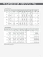
6.1.1 Gate valves
Typical
configurations for gate valves with flanged and welding ends are shown, for illustration purposes only,
in
Figures 1 and
2.
Gate valves shall have
an
obturator that moves
in
a plane perpendicular to the direction of flow. The gate can
be
constructed of one piece for slab-gate valves or
of
two or more pieces for expanding-gate valves.
Gate valves shall
be
provided with a back seat or secondary stem sealing feature
in
addition to the primary
stem
seal.
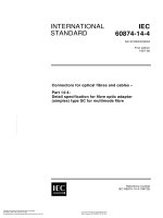
6.1.2 Lubricated and non-lubricated plug valves
Typical
configurations for plug valves with flanged and welding ends are shown, for illustration purposes only,
in
Figure
3.
Plug valves shall have a cylindrical or conical obturator that rotates about an axis perpendicular
to
the
direction of
flow.
8
API Specification
6D
/ ISO 14313
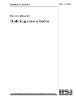
6.1.3 Ball
valves
Typical configurations for ball valves with flanged or welding ends are shown, for illustration purposes only,
in
Figures 4, 5 and
6.
Ball valves shall have a spherical obturator that rotates
on
an
axis perpendicular to the direction of flow.
6.1.4 Check valves
Typical configurations for check valves are shown, for illustration purposes only,
in
Figures 7 to
13.
Check
valves can also be of the wafer, axial flow and lift type.
Check valves shall have
an
obturator which responds automatically to block fluid
in
one direction.
6.2 Valve
configurations
6.2.1 Full-opening valves
Full-opening flanged-end valves shall
be
unobstructed
in
the fully opened position and shall have
an
internal
bore as specified
in
Table
1.
There
is
no restriction
on
the upper limit of valve bore sizes.
Full-opening through-conduit valves shall have a circular bore
in
the obturator that allows a sphere to pass
with a nominal size not less than that specified
in
Table
1.
Welding-end valves can require a smaller bore at the welding end to mate with the pipe.
Valves with a non-circular opening through the obturator
shall not
be
considered full opening.
6.2.2 Reduced-opening valves
Reduced-opening valves with a circular opening through the obturator shall be supplied with a minimum bore
as
follows, unless otherwise specified:
valves
ON
300 (NPS 12) and below: one size below nominal size of valve with bore according to Table
1;
valves
ON
350 (NPS 14) to
ON
600 (NPS 24): two sizes below nominal size
of
valve with bore according
to Table
1;
valves above
ON
600 (NPS 24): by agreement.
EXAMPLE A
DN
400 (NPS 16) -
PN
250 (class 1500) reduced-opening ball valve has a minimum bore of 287
mm.
Reduced-opening valves with a non-circular opening through the obturator shall be supplied with a minimum
opening by agreement.
9
API Specification
60
II
SO 14313
Table 1 - Minimum bore for full-opening valves
Minimum bore by class
mm
ON
NPS
PN
20 to 100
PN
150
PN
250
PN
420
(Class 150
to 600) (Class 900)
(Class
1 500) (Class 2 500)
15
%
13
13
13 13
20
%
19
19 19
19
25
1
25
25
25
25
32
11;4
32
32
32
32
40
1%
38
38
38 38
50
2
49
49
49
42
65
2%
62
62
62
52
80
3
74
74
74
62
100 4
100
100
100
87
150
6 150
150
144
131
200 8
201
201
192 179
250
10
252
252
239
223
300
12
303
303
287 265
350
14
334
322
315
292
400
16
385 373
360
333
450
18
436
423
406 374
500
20
487
471
454
419
550
22
538
522
500
-
600
24
589
570
546
-
650
26
633 617 594
-
700
28
684
665
641
-
750
30
735
712
686
-
800
32
779
760
730
-
850
34
830 808
775
-
900
36
874 855
819
-
950
38
925
904 -
-
1 000
40
976
956
-
-
1 050
42
1 020 1
006
-
-
1 200
48
1 166 1
149
-
-
1 350
54
1 312
-
-
-
1 400
56
1 360
-
-
-
1 500
60
1 458
-
- -
10
Key
stem indicator
2 stem enclosure
3
handwheel
4 yoke nut
5
yoke
6
stem
7 yoke
bolting
8
stem packing
9
relief valve
10
bonnet
11
bonnet bolting
12
gate guide
13
gate
assembly
14
seat ring
15 body
16
support ribs or
legs
17 raised face
18
welding end
19
ring joint
A raised-face face-to-face
dimension
B
welding-end end-to-end
dimension
C
ring-joint end-to-end
dimension
NOTE See Tables 2 to
6 for dimensions
A,
Band
C.
18
API Specification 6D
liSa
14313
17
B
111 1
~ 2
~ 5
~ 6
7
11
~~;;:::
8
' 9
' 10
' 13
Iet t
14
<.,(/,,'1
15
~' +
12
~~~ + 16
A
[
Figure 1 - Expanding-gate/rising-stem gate valve
11
Key
1 stem indicator
2 stem enclosure
3
hand-wheel
4 yoke nut
5
yoke
6 stem
7 yoke bolting
8 stem packing
9 relief valve
10
bonnet
11
bonnet bolting
12
gate
13
seat ring
14
body
15 support ribs or
legs
16
raised face
17
welding end
18 ring joint
A
raised-face face-
to-face dimension
B
welding-end end-
to-end dimension
C
ring-joint end-to-
end dimension
NOTE
See
Tables 2 to 6 for
dimensions
A,
Band
C.
16
17
API Specification
60
liSa
14313
w 1
~
2
~ 3
::4=1~_ _~""
~============~~~===~~-4
8
~
5
~
6
7
11
~~::
8
"'
9
10
12
13
111 1 _
14
~~~ ~ 15
A
I-,-,-,.~~
18
'LLV""~It'Z,{/
A
(
Figure 2 - Siab-gate/through-conduit rising-stem gate valve
12
API Specification
60/
ISO 14313
7
8
12
9
10
11
Key
lubricator screw
2
gland studs and nuts
A
3
gland
4 cover studs and nuts
5
cover
6
cover gasket
7 stem packing
13
8 lubricant check valve
9
plug
10
body
B
11
stop collar
12
raised face
13
welding end
14 ring joint
A raised-face face-to-face dimension
B
welding-end end-to-end dimension
14
C
ring-joint end-to-end dimension
NOTE See Tables 2 to 6 for
(
dimensions
A,
Band
C.
Figure 3 - Plug valve
13
Key
1 stem
seal
2 bonnet cover
3 bonnet
4 body bolting
5 body
6 seat
ring
7 stem
8 ball
9 raised face
10
welding end
11
ring joint
A raised-face face-to-face dimension
B welding-end end-to-end dimension
C ring-joint end-to-end dimension
NOTE See Tables 2
to
6 for
dimensions
A,
Band
C.
API
Specification
60
IISO
14313
9
t
"
Figure 4 - Top-entry ball valve
14
A
B
[
r 1
2
r 3
~ili.,~ w.u___
4
"~I
5
' ~ I
6
~4 ~ 4 7
~1 I-4 I 8
11
Key
1
stem
2 body cover
3 stem seal
4
body
5
seat ring
6
ball
7 body bolting
8 closure
9
raised face
10 welding end
11
ring joint
A raised-face face-to-face dimension
B welding-end end-to-end dimension
C ring-joint end-to-end dimension
NOTE See Tables 2 to 6 for
dimensions
A,
Band
C.
API Specification 6D
liSa
14313
9
r 1
~ 2
~ 3
,,
4
'~ + 5
~~ 1_
6
~ ~
8
A
._.+._.
I
10
B
._.+._.
I
11
(
Figure 5 - Three-piece ball valve
15