roberge pierre r.- handbook of corrosion engineering
Bạn đang xem bản rút gọn của tài liệu. Xem và tải ngay bản đầy đủ của tài liệu tại đây (8.59 MB, 1,130 trang )
Handbook of
Corrosion
Engineering
Pierre R. Roberge
McGraw-Hill
New York San Francisco Washington, D.C. Auckland Bogotá
Caracas Lisbon London Madrid Mexico City Milan
Montreal New Delhi San Juan Singapore
Sydney Tokyo Toronto
0765162_FM_Roberge 9/1/99 2:36 Page iii
Library of Congress Cataloging-in-Publication Data
Roberge, Pierre R.
Handbook of Corrosion Engineering / Pierre R. Roberge.
p. cm.
Includes bibliographical references.
ISBN 0-07-076516-2 (alk. paper)
1. Corrosion and anti-corrosives. I. Title.
TA418.74.R63 1999
620.1'1223—dc21 99-35898
CIP
Copyright © 2000 by The McGraw-Hill Companies, Inc. All rights
reserved. Printed in the United States of America. Except as permit-
ted under the United States Copyright Act of 1976, no part of this
publication may be reproduced or distributed in any form or by any
means, or stored in a data base or retrieval system, without the prior
written permission of the publisher.
1 2 3 4 5 6 7 8 9 AGM/AGM 9 0 4 3 2 1 0 9
ISBN 0-07-076516-2
The sponsoring editor of this book was Robert Esposito. The editing
supervisor was David E. Fogarty, and the production supervisor was
Sherri Souffrance. This book was set in New Century Schoolbook by
Joanne Morbit and Paul Scozzari of McGraw-Hill’s Professional Book
Group in Hightstown, N.J.
Printed and bound by Quebecor/Martinsburg.
This book was printed on recycled, acid-free paper contain-
ing a minimum of 50% recycled, de-inked fiber.
McGraw-Hill books are available at special quantity discounts to use
as premiums and sales promotions, or for use in corporate training
programs. For more information, please write to the Director of Special
Sales, McGraw-Hill, 11 West 19th Street, New York, NY 10011. Or
contact your local bookstore.
McGraw-Hill
Information contained in this work has been obtained by The McGraw-Hill
Companies, Inc. (“McGraw-Hill) from sources believed to be reliable. However,
neither McGraw-Hill nor its authors guarantee the accuracy or completeness
of any information published herein and neither McGraw-Hill nor its authors
shall be responsible for any errors, omissions, or damages arising out of use of
this information. This work is published with the understanding that
McGraw-Hill and its authors are supplying information but are not attempt-
ing to render engineering or other professional services. If such services are
required, the assistance of an appropriate professional should be sought.
0765162_FM_Roberge 9/1/99 2:36 Page iv
Contents
Preface ix
Acknowledgments xi
Introduction 1
1.1 The Cost of Corrosion 1
1.2 Examples of Catastrophic Corrosion Damage 3
1.3 The Influence of People 5
References 12
Chapter 1. Aqueous Corrosion 13
1.1 Introduction 13
1.2 Applications of Potential-pH Diagrams 16
1.3 Kinetic Principles 32
References 54
Chapter 2. Environments 55
2.1 Atmospheric Corrosion 58
2.2 Natural Waters 85
2.3 Seawater 129
2.4 Corrosion in Soils 142
2.5 Reinforced Concrete 154
2.6 Microbes and Biofouling 187
References 216
Chapter 3. High-Temperature Corrosion 221
3.1 Thermodynamic Principles 222
3.2 Kinetic Principles 229
3.3 Practical High-Temperature Corrosion Problems 237
References 265
0765162_FM_Roberge 9/1/99 2:36 Page v
Chapter 4. Modeling, Life Prediction and Computer Applications 267
4.1 Introduction 267
4.2 Modeling and Life Prediction 268
4.3 Applications of Artificial Intelligence 303
4.4 Computer-Based Training or Learning 322
4.5 Internet and the Web 324
References
Chapter 5. Corrosion Failures 331
5.1 Introduction 332
5.2 Mechanisms, Forms, and Modes of Corrosion Failures 332
5.3 Guidelines for Investigating Corrosion Failures 359
5.4 Prevention of Corrosion Damage 360
5.5 Case Histories in Corrosion Failure Analysis 368
References 369
Chapter 6. Corrosion Maintenance Through Inspection And Monitoring 371
6.1 Introduction 372
6.2 Inspection 374
6.3 The Maintenance Revolution
6.4 Monitoring and Managing Corrosion Damage 406
6.5 Smart Sensing of Corrosion with Fiber Optics 448
6.6 Non-destructive Evaluation (NDE) 461
References 481
Chapter 7. Acceleration and Amplification of Corrosion Damage 485
7.1 Introduction 486
7.2 Corrosion Testing 488
7.3 Surface Characterization 562
References 574
Chapter 8. Materials Selection 577
8.1 Introduction 578
8.2 Aluminum Alloys 584
8.3 Cast Irons 612
8.4 Copper Alloys 622
8.5 High-Performance Alloys 664
8.6 Refractory Metals 692
8.7 Stainless Steels 710
8.8 Steels 736
8.9 Titanium 748
8.10 Zirconium 769
References 777
Chapter 9. Protective Coatings 781
9.1 Introduction 781
9.2 Coatings and Coating Processes 782
Contents
0765162_FM_Roberge 9/1/99 2:36 Page vi
326
383
9.3 Supplementary Protection Systems 829
9.4 Surface Preparation 831
References 831
Chapter 10. Corrosion Inhibitors 833
10.1 Introduction 833
10.2 Classification of Inhibitors 834
10.3 Corrosion Inhibition Mechanism 838
10.4 Selection of an Inhibitor System 860
References 861
Chapter 11. Cathodic Protection 863
11.1 Introduction 863
11.2 Sacrificial Anode CP Systems 871
11.3 Impressed Current Systems 878
11.4 Current Distribution and Interference Issues 886
11.5 Monitoring the Performance of CP Systems for Buried Pipelines 904
References 919
Chapter 12. Anodic Protection 921
12.1 Introduction 921
12.2 Passivity of Metals 923
12.3 Equipment Required for Anodic Protection 927
12.4 Design Concerns 930
12.5 Applications 932
12.6 Practical Example: Anodic Protection in the Pulp and Paper Industry 933
References 938
Appendix A. SI Units 939
Appendix B. Glossary 947
Appendix C. Corrosion Economics 1001
C.1 Introduction 1001
C.2 Cash Flows and Capital Budgeting Techniques 1002
C.3 Generalized Equation for Straight Line Depreciation 1004
C.4 Examples 1006
C.5 Summary 1009
References 1009
Appendix D. Electrochemistry Basics 1011
D.1 Principles of Electrochemistry 1011
D.2 Chemical Thermodynamics 1029
D.3 Kinetic Principles 1047
0765162_FM_Roberge 9/1/99 2:36 Page vii
Appendix E. Chemical Compositions of Engineering Alloys 1061
Appendix F. Thermodynamic Data and E-pH Diagrams 1101
Appendix G. Densities and Melting Points of Metals 1125
Index 1129
Contents
0765162_FM_Roberge 9/1/99 2:36 Page viii
Preface
The design and production of the Handbook of Corrosion Engineering
are drastically different than other handbooks dealing with the same
subject. While other corrosion handbooks have been generally the
results of collective efforts of many authors, the Handbook of
Corrosion Engineering is the result of an extensive survey of state-of-
the-art information on corrosion engineering by a principal author.
Although only one author appears on the cover, this Handbook is
indeed the result of cumulative efforts of many generations of scien-
tists and engineers in understanding and preventing the effects of cor-
rosion, one of the most constant foes of human endeavors. The design
and construction of this Handbook were made for the new millennium
with the most modern information-processing techniques presently
available. Many references are made to sources of information readily
accessible on the World Wide Web and to software systems that can
simplify the most difficult situation. It also provides elements of infor-
mation management and tools for managing corrosion problems that
are particularly valuable to practicing engineers. Many examples, for
example, describe how various industries and agencies have addressed
corrosion problems. The systems selected as supportive examples have
been chosen from a wide range of applications across various industries,
from aerospace structures to energy carriers and producers.
This Handbook is aimed at the practicing engineer, as a comprehen-
sive guide and reference source for solving material selection problems
and resolving design issues where corrosion is possibly a factor.
During the past decades, progress in the development of materials
capable of resisting corrosion and high temperatures has been signifi-
cant. There have been substantial developments in newer stainless
steels, high-strength low-alloy steels, superalloys, and in protective
coatings. This Handbook should prove to be a key information source
concerning numerous facets of corrosion damage, from detection and
monitoring to prevention and control.
The Handbook is divided into three main sections and is followed by
supporting material in seven appendixes. Each section and its chapters
are relatively independent and can be consulted without having to go
through previous chapters. The first main section (Introduction and
0765162_FM_Roberge 9/1/99 2:36 Page ix
Chapters 1 to 3) contains fundamental principles governing aqueous
corrosion and high-temperature corrosion and covers the main environ-
ments causing corrosion such as atmospheric, natural waters, seawater,
soils, concrete, as well as microbial and biofouling environments.
The second section (Chapters 4 to 7) addresses techniques for the pre-
diction and assessment of corrosion damage such as modeling, life pre-
diction, computer applications, inspection and monitoring and testing
through acceleration and amplification of corrosion damage. The second
section also contains a detailed description of the various types of corro-
sion failures with examples and ways to prevent them. The third section
(Chapters 8 to 12) covers general considerations of corrosion prevention
and control with a focus on materials selection. This chapter is particu-
larly valuable for its detailed descriptions of the performance and main-
tenance considerations for the main families of engineering alloys based
on aluminum, copper, nickel, chrome, refractory metals, titanium and
zirconium, as well as cast irons, stainless steels and other steels. This
section also provides elements for understanding protective coatings,
corrosion inhibitors, cathodic protection and anodic protection.
The first appendix contains a table of appropriate SI units making
references to most other types of units. This table will hopefully com-
pensate for the systematic usage of SI units made in the book. Another
appendix is an extensive glossary of terms often used in the context of
corrosion engineering. A third appendix summarizes corrosion econom-
ics with examples detailing calculations based on straight value depre-
ciation. The fourth appendix provides a detailed introduction to basic
electrochemical principles. Many examples of E-pH (Pourbaix) dia-
grams are provided in a subsequent appendix. The designations and
compositions of engineering alloys is the subject of a fifth appendix.
Pierre R. Roberge
Preface
0765162_FM_Roberge 9/1/99 2:36 Page x
Acknowledgments
The Handbook of Corrosion Engineering was designed entirely in collab-
oration with Martin Tullmin. In fact, Martin is the sole author of many
sections of the book (corrosion in concrete, soil corrosion and cathodic
protection) as well as an important contributor to many others. My
acknowledgments also go to Robert Klassen who contributed to the
atmospheric corrosion section as well as for his study of the fiber optic
sensors for corrosion monitoring.
As I mentioned in the Preface, this book tries to summarize the pre-
sent state of our knowledge of the corrosion phenomena and their
impact on our societies. Many of the opinions expressed in the
Handbook have come either from my work with collaborators or, more
often, from my study of the work of other corrosion engineers and sci-
entists. Of the first kind I am particularly indebted to Ken Trethewey
with whom I have had many enlightening discussions that sometimes
resulted in published articles. I also have to thank the congenial
experts I interacted with in corrosion standard writing committees
(ISO TC 156 and ASTM G01) for their expert advice and the rigor that
is required in the development of new procedures and test methods.
Of the second kind I have to recognize the science and engineering
pillars responsible for the present state of our knowledge in corrosion.
The names of some of these giants have been mentioned throughout
the book with a particular recognition made in the Introduction in
Table I.4. In this respect, my personal gratitude goes to Professor Roger
Staehle for his pragmatic vision of the quantification of corrosion dam-
age. I have been greatly inspired by the work of this great man.
I would also like to take this occasion to express my love to those
close to me, and particularly to Diane whose endurance of my working
habits is phenomenal.
0765162_FM_Roberge 9/1/99 2:36 Page xi
1
I.1 The Cost of Corrosion 1
I.2 Examples of Catastrophic Corrosion Damage 3
I.2.1 Sewer explosion, Mexico 3
I.2.2 Loss of USAF F16 fighter aircraft 3
I.2.3 The Aloha aircraft incident 3
I.2.4 The MV KIRKI 4
I.2.5 Corrosion of the infrastructure 4
I.3 The Influence of People 5
Introduction
Corrosion is the destructive attack of a material by reaction with its
environment. The serious consequences of the corrosion process have
become a problem of worldwide significance. In addition to our every-
day encounters with this form of degradation, corrosion causes plant
shutdowns, waste of valuable resources, loss or contamination of prod-
uct, reduction in efficiency, costly maintenance, and expensive over-
design; it also jeopardizes safety and inhibits technological progress.
The multidisciplinary aspect of corrosion problems combined with the
distributed responsibilities associated with such problems only
increase the complexity of the subject. Corrosion control is achieved by
recognizing and understanding corrosion mechanisms, by using corro-
sion-resistant materials and designs, and by using protective systems,
devices, and treatments. Major corporations, industries, and govern-
ment agencies have established groups and committees to look after
corrosion-related issues, but in many cases the responsibilities are
spread between the manufacturers or producers of systems and their
users. Such a situation can easily breed negligence and be quite cost-
ly in terms of dollars and human lives.
I.1 The Cost of Corrosion
Although the costs attributed to corrosion damages of all kinds have
been estimated to be of the order of 3 to 5 percent of industrialized
countries’ gross national product (GNP), the responsibilities associat-
ed with these problems are sometimes quite diffuse. Since the first sig-
nificant report by Uhlig
1
in 1949 that the cost of corrosion to nations
is indeed great, the conclusion of all subsequent studies has been that
corrosion represents a constant charge to a nation’s GNP.
2
One conclu-
sion of the 1971 UK government-sponsored report chaired by Hoar
3
was that a good fraction of corrosion failures were avoidable and that
improved education was a good way of tackling corrosion avoidance.
0765162_Intro_Roberge 9/1/99 2:38 Page 1
Corrosion of metals cost the U.S. economy almost $300 billion per
year at 1995 prices.
4
Broader application of corrosion-resistant mate-
rials and the application of the best corrosion-related technical prac-
tices could reduce approximately one-third of these costs. These
estimates result from a recent update by Battelle scientists of an ear-
lier study reported in 1978.
5
The initial work, based upon an elaborate
model of more than 130 economic sectors, had revealed that metallic
corrosion cost the United States $82 billion in 1975, or 4.9 percent of
its GNP. It was also found that 60 percent of that cost was unavoid-
able. The remaining $33 billion (40 percent) was said to be “avoidable”
and incurred by failure to use the best practices then known.
In the original Battelle study, almost 40 percent of 1975 metallic cor-
rosion costs were attributed to the production, use, and maintenance
of motor vehicles. No other sector accounted for as much as 4 percent
of the total, and most sectors contributed less than 1 percent. The 1995
Battelle study indicated that the motor vehicles sector probably had
made the greatest anticorrosion effort of any single industry. Advances
have been made in the use of stainless steels, coated metals, and more
protective finishes. Moreover, several substitutions of materials made
primarily for reasons of weight reduction have also reduced corrosion.
Also, the panel estimated that 15 percent of previously unavoidable
corrosion costs can be reclassified as avoidable. The industry is esti-
mated to have eliminated some 35 percent of its “avoidable” corrosion
by its improved practices. Table I.1 summarizes the costs attributed to
metallic corrosion in the United States in these two studies.
2 Introduction
TABLE I.1 Costs Attributed to Metallic Corrosion
in the United States
1975 1995
All industries
Total (billions of 1995 dollars) $82.5 $296.0
Avoidable $33.0 $104.0
Avoidable 40% 35%
Motor vehicles
Total $31.4 $94.0
Avoidable $23.1 $65.0
Avoidable 73% 69%
Aircraft
Total $3.0 $13.0
Avoidable $0.6 $3.0
Avoidable 20% 23%
Other industries
Total $47.6 $189.0
Avoidable $9.3 $36.0
Avoidable 19% 19%
0765162_Intro_Roberge 9/1/99 2:38 Page 2
I.2 Examples of Catastrophic
Corrosion Damage
I.2.1 Sewer explosion, Mexico
An example of corrosion damages with shared responsibilities was the
sewer explosion that killed over 200 people in Guadalajara, Mexico, in
April 1992.
6
Besides the fatalities, the series of blasts damaged 1600
buildings and injured 1500 people. Damage costs were estimated at 75
million U.S. dollars. The sewer explosion was traced to the installation
of a water pipe by a contractor several years before the explosion that
leaked water on a gasoline line laying underneath. The subsequent
corrosion of the gasoline pipeline, in turn, caused leakage of gasoline
into the sewers. The Mexican attorney general sought negligent homi-
cide charges against four officials of Pemex, the government-owned oil
company. Also cited were three representatives of the regional sewer
system and the city’s mayor.
I.2.2 Loss of USAF F16 fighter aircraft
This example illustrates a case that has recently created problems in
the fleet of USAF F16 fighter aircraft. Graphite-containing grease is a
very common lubricant because graphite is readily available from steel
industries. The alternative, a formulation containing molybdenum
disulphide, is much more expensive. Unfortunately, graphite grease is
well known to cause galvanically induced corrosion in bimetallic cou-
ples. In a fleet of over 3000 F16 USAF single-engine fighter aircraft,
graphite grease was used by a contractor despite a general order from
the Air Force banning its use in aircraft.
7
As the flaps were operated,
lubricant was extruded into a part of the aircraft where control of the
fuel line shutoff valve was by means of electrical connectors made from
a combination of gold- and tin-plated steel pins. In many instances cor-
rosion occurred between these metals and caused loss of control of the
valve, which shut off fuel to the engine in midflight. At least seven air-
craft are believed to have been lost in this way, besides a multitude of
other near accidents and enormous additional maintenance.
I.2.3 The Aloha aircraft incident
The structural failure on April 28, 1988, of a 19-year-old Boeing 737,
operated by Aloha airlines, was a defining event in creating awareness
of aging aircraft in both the public domain and in the aviation commu-
nity. This aircraft lost a major portion of the upper fuselage near the
front of the plane in full flight at 24,000 ft.
8
Miraculously, the pilot man-
aged to land the plane on the island of Maui, Hawaii. One flight atten-
dant was swept to her death. Multiple fatigue cracks were detected
Introduction 3
0765162_Intro_Roberge 9/1/99 2:38 Page 3
in the remaining aircraft structure, in the holes of the upper row of riv-
ets in several fuselage skin lap joints. Lap joints join large panels of
skin together and run longitudinally along the fuselage. Fatigue crack-
ing was not anticipated to be a problem, provided the overlapping pan-
els remained strongly bonded together. Inspection of other similar
aircraft revealed disbonding, corrosion, and cracking problems in the
lap joints. Corrosion processes and the subsequent buildup of volumi-
nous corrosion products inside the lap joints, lead to “pillowing,” where-
by the faying surfaces are separated. Special instrumentation has been
developed to detect this dangerous condition. The aging aircraft prob-
lem will not go away, even if airlines were to order unprecedented num-
bers of new aircraft. Older planes are seldom scrapped, and the older
planes that are replaced by some operators will probably end up in ser-
vice with another operator. Therefore, safety issues regarding aging
aircraft need to be well understood, and safety programs need to be
applied on a consistent and rigorous basis.
I.2.4 The MV KIRKI
Another example of major losses to corrosion that could have been pre-
vented and that was brought to public attention on numerous occa-
sions since the 1960s is related to the design, construction, and
operating practices of bulk carriers. In 1991 over 44 large bulk carri-
ers were either lost or critically damaged and over 120 seamen lost
their lives.
9
A highly visible case was the MV KIRKI, built in Spain in
1969 to Danish designs. In 1990, while operating off the coast of
Australia, the complete bow section became detached from the vessel.
Miraculously, no lives were lost, there was little pollution, and the ves-
sel was salvaged. Throughout this period it seems to have been com-
mon practice to use neither coatings nor cathodic protection inside
ballast tanks. Not surprisingly therefore, evidence was produced that
serious corrosion had greatly reduced the thickness of the plate and
that this, combined with poor design to fatigue loading, were the pri-
mary cause of the failure. The case led to an Australian Government
report called “Ships of Shame.” MV KIRKI is not an isolated case.
There have been many others involving large catastrophic failures,
although in many cases there is little or no hard evidence when the
ships go to the bottom.
I.2.5 Corrosion of the infrastructure
One of the most evident modern corrosion disasters is the present state
of degradation of the North American infrastructure, particularly in
the snow belt where the use of road deicing salts rose from 0.6M ton in
1950 to 10.5M tons in 1988. The structural integrity of thousands of
4 Introduction
0765162_Intro_Roberge 9/1/99 2:38 Page 4
bridges, roadbeds, overpasses, and other concrete structures has been
impaired by corrosion, urgently requiring expensive repairs to ensure
public safety. A report by the New York Department of Transport has
stated that, by 2010, 95 percent of all New York bridges would be defi-
cient if maintenance remained at the same level as it was in 1981.
Rehabilitation of such bridges has become an important engineering
practice.
10
But the problems of corroding reinforced concrete extend
much beyond the transportation infrastructure. A survey of collapsed
buildings during the 1974 to 1978 period in England showed that the
immediate cause of failure of at least eight structures, which were 12
to 40 years old, was corrosion of reinforcing or prestressing steel.
Deterioration of parking garages has become a major concern in
Canada. Of the 215 garages surveyed recently, almost all suffered vary-
ing degrees of deterioration due to reinforcement corrosion, which was
a result of design and construction practices that fell short of those
required by the environment. It is also stated that almost all garages
in Canada built until very recently by conventional methods will
require rehabilitation at a cost to exceed $3 billion. The problem sure-
ly extends to the northern United States. In New York, for example, the
seriousness of the corrosion problem of parking garages was revealed
dramatically during the investigation that followed the bomb attack on
the underground parking garage of the World Trade Center.
11
I.3 The Influence of People
The effects of corrosion failures on the performance maintenance of
materials would often be minimized if life monitoring and control of the
environmental and human factors supplemented efficient designs.
When an engineering system functions according to specification, a
three-way interaction is established with complex and variable inputs
from people (p), materials (m), and environments (e).
12
An attempt to
translate this concept into a fault tree has produced the simple tree
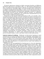
presented in Fig. I.1 where the consequence, or top event, a corrosion
failure, can be represented by combining the three previous contribut-
ing elements. In this representation, the top event probability (P
sf
) can
be evaluated with boolean algebra, which leads to Eq. (I.1) where P
m
and P
e
are, respectively, the probability of failure caused by materials
and by the environment, and Factor
p
describes the influence of people
on the lifetime of a system. In Eq. (I.1), Factor
p
can be either inhibiting
(Factor
p
Ͻ1) or aggravating (Factor
p
Ͼ1):
P
sf
ϭ P
m
P
e
Factor
p
(I.1)
The justification for including the people element as an inhibit gate or
conditional event in the corrosion tree should be obvious (i.e., corrosion
Introduction 5
0765162_Intro_Roberge 9/1/99 2:38 Page 5
is a natural process that does not need human intervention to occur).
What might be defined as purely mechanical failures occur when P
m
is
high and P
e
is low. Most well-designed engineering systems in which P
e
is approximately 0 achieve good levels of reliability. The most successful
systems are usually those in which the environmental influence is very
small and continues to be so throughout the service lifetime. When P
e
becomes a significant influence on an increasing P
sf
, the incidence of cor-
rosion failures normally also increases.
Minimizing P
sf
only through design is difficult to achieve in practice
because of the number of ways in which P
m
, P
e
, and Factor
p
can vary
during the system lifetime. The types of people that can affect the life
and performance of engineering systems have been regrouped in six
categories (Table I.2).
13
Table I.2 also contains a brief description of the
main contributions that each category of people can make to the suc-
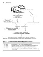
cess or premature failure of a system. Table I.3 gives an outline of
methods of corrosion control
14
with an indication of the associated
responsibility.
However, the influence of people in a failure is extremely difficult to
predict, being subject to the high variability level in human decision
making. Most well-designed engineering systems perform according to
specification, largely because the interactions of people with these sys-
tems are tightly controlled and managed throughout the life of the sys-
tems. Figure I.2 breaks down the causes responsible for failures
6 Introduction
People (p)
m
Corrosion Failure
Environmental
Influence
Materials
in Service
e
Figure I.1 Basic fault tree of a corrosion failure.
0765162_Intro_Roberge 9/1/99 2:38 Page 6
Introduction 7
TABLE I.2 Positions and Their Relative Responsibilities in System Management
Procurer
What is the main system being specified?
What is the function of the main system?
Did the budget introduce compromise into the design?
How was a subsystem embodied into the main system?
Does the envelope of the subsystems fit that for the main system?
Designer
What is the subsystem being specified for?
What is the function of the subsystem?
What is the optimum materials selection?
Has the correct definition of the operating environment been applied?
By what means will the component be manufactured?
What is the best geometrical design?
Have finishing operations, protective coatings, or corrosion control techniques been
specified?
Have the correct operating conditions been specified?
Has the best maintenance schedule been specified?
Does the design embody features that enable the correct maintenance procedures to be
followed?
Manufacturer
Were the same materials used as were originally specified?
Did the purchased starting materials conform to the specification in the order?
Has the manufacturing process been carried out correctly?
Has the design been reproduced accurately and has the materials specification been
precisely followed?
Have the correct techniques been used?
Have the most suitable joining techniques been employed?
Have the specified conditions/coatings necessary for optimum performance been
implemented?
Did the component conform to the appropriate quality control standards?
Was the scheme for correct assembly of the subsystem implemented correctly so that
the installation can be made correctly?
Installer
Has the system been installed according to specification?
Has the correct setting-to-work procedure been followed?
Have any new features in the environment been identified that are likely to exert an
influence and were not foreseen by the design process?
Maintainer
Has the correct maintenance schedule been followed?
Have the correct spares been used in repairs?
Have the correct maintenance procedures been carried out?
Has the condition of the system been correctly monitored?
User
Has the system been used within the specified conditions?
Is there a history of similar failures or is this an isolated occurrence?
Do aggravating conditions exist when the system is not in use?
Is there any evidence that the system has been abused by unauthorized personnel?
0765162_Intro_Roberge 9/1/99 2:38 Page 7
8 Introduction
TABLE I.3 Outline of Methods of Corrosion Control
Method Responsibility
Selection of Materials Direct Managerial
Select metal or alloy (on nonmetallic material) Designer Procurer (for user)
for the particular environmental conditions
prevailing (composition, temperature, velocity,
etc.), taking into account mechanical and
physical properties, availability, method of
fabrication and overall cost of structure
Decide whether or not an expensive corrosion- Designer Procurer (for user)
resistant alloy is more economical than a
cheaper metal that requires protection and
periodic maintenance
Design
If the metal has to be protected, make Designer Designer
provision in the design for applying metallic
or nonmetallic coatings or applying anodic or
cathodic protection
Avoid geometrical configurations that facilitate Designer Designer
corrosive conditions such as
Features that trap dust, moisture, and water
Crevices (or else fill them in) and situations
where deposits can form on the metal surface
Designs that lead to erosion corrosion or to
cavitation damage
Designs that result in inaccessible areas
that cannot be reprotected (e.g., by
maintenance painting)
Designs that lead to heterogeneities in the
metal (differences in thermal treatment)
or in the environment (differences in
temperature, velocity)
Contact with other materials
Avoid metal-metal or metal-nonmetallic Designer, user Designer, user
contacting materials that facilitate corrosion
such as
Bimetallic couples in which a large area of
a more positive metal (e.g., Cu) is in contact
with a small area of a less noble metal
(e.g., Fe, Zn, or Al)
Metals in contact with absorbent materials
that maintain constantly wet conditions or,
in the case of passive metals, that exclude
oxygen
Contact (or enclosure in a confined space)
with substances that give off corrosive
vapors (e.g., certain woods and plastics)
Mechanical factors
Avoid stresses (magnitude and type) and Designer, user Designer, user
environmental conditions that lead to stress-
corrosion cracking, corrosion fatigue, or
fretting corrosion:
0765162_Intro_Roberge 9/1/99 2:38 Page 8
TABLE I.3 Outline of Methods of Corrosion Control (Continued)
Method Responsibility
Selection of Materials Direct Managerial
For stress corrosion cracking, avoid the use
of alloys that are susceptible in the
environment under consideration, or if
this is not possible, ensure that the
external and internal stresses are kept
to a minimum.
For a metal subjected to fatigue conditions
in a corrosive environment ensure that
the metal is adequately protected by a
corrosion-resistant coating.
Processes that induce compressive stresses
into the surface of the metal such as shot-
peening, carburizing, and nitriding are
frequently beneficial in preventing
corrosion fatigue and fretting corrosion.
Coatings
If the metal has a poor resistance to corrosion Designer Designer
in the environment under consideration,
make provision in the design for applying an
appropriate protective coating such as
Metal reaction products (e.g., anodic oxide
films on Al), phosphate coatings on steel
(for subsequent painting or impregnation
with grease), chromate films on light
metals and alloys (Zn, Al, cd, Mg)
Metallic coatings that form protective
barriers (Ni, Cr) and also protect the
substrate by sacrificial action (Zn, Al, or
cd on steel)
Inorganic coatings (e.g., enamels, glasses, ceramics)
Organic coatings (e.g., paints, plastics,
greases)
Environment
Make environment less aggressive by Designer, user Designer, user
removing constituents that facilitate
corrosion; decrease temperatures decrease
velocity; where possible prevent access of
water and moisture.
For atmospheric corrosion dehumidify the
air, remove solid particles, add volatile
corrosion inhibitors (for steel).
For aqueous corrosion remove dissolved O
2
,
increase the pH (for steels), add inhibitors.
Interfacial potential
Protect metal cathodically by making the
interfacial potential sufficiently negative by
(1) sacrificial anodes or (2) impressed current.
Protect metal by making the interfacial
potential sufficiently positive to cause
passivation (confined to metals that passivate
in the environment under consideration).
9
0765162_Intro_Roberge 9/1/99 2:38 Page 9
10 Introduction
TABLE I.3 Outline of Methods of Corrosion Control (Continued)
Method Responsibility
Selection of Materials Direct Managerial
Corrosion testing and monitoring
When there is no information on the behavior Designer Designer, user
of a metal or alloy or a fabrication under
specific environmental conditions (a newly
formulated alloy and/or a new environment),
it is essential to carry out corrosion testing.
Monitor composition of environment, corrosion Designer Designer, user
rate of metal, interfacial potential, and so forth,
to ensure that control is effective.
Supervision and inspection
Ensure that the application of a protective Designer, user User
coating (applied in situ or in a factory) is
adequately supervised and inspected in
accordance with the specification or code
of practice.
Lack of proving
(new design, material, or process)
36%
Poor planning and
coordination
14%
Unforeseeable
8%
Other causes
4%
Human error
12%
Bad inspection
10%
Lack of, or wrong,
specification
16%
Figure I.2 Pie chart attribution of responsibility for corrosion failures investigated by a
large chemical company.
0765162_Intro_Roberge 9/1/99 2:38 Page 10
investigated by a large process industry.
15
But the battle against such
an insidious foe has been raging for a long time and sometimes with
success. Table I.4 presents some historical landmarks of discoveries
related to the understanding and management of corrosion. Although
the future successes will still relate to improvements in materials and
their performance, it can be expected that the main progress in corro-
sion prevention will be associated with the development of better infor-
mation-processing strategies and the production of more efficient
monitoring tools in support of corrosion control programs.
Introduction 11
TABLE I.4 Landmarks of Discoveries Related to the Understanding and
Management of Corrosion
Date Landmark Source
1675 Mechanical origin of corrosiveness
and corrodibility Boyle
1763 Bimetallic corrosion HMS Alarm report
1788 Water becomes alkaline during corrosion
of iron Austin
1791 Copper-iron electrolytic galvanic coupling Galvani
1819 Insight into electrochemical nature of
corrosion Thenard
1824 Cathodic protection of Cu by Zn or Fe Sir Humphrey Davy
1830 Microstructural aspect of corrosion (Zn) De la Rive
1834–1840 Relations between chemical action and
generation of electric currents Faraday
1836 Passivity of iron Faraday, Schoenbein
1904 Hydrogen overvoltage as a function of current Tafel
1905 Carbonic and other acids are not essential Dunstan, Jowett,
for the corrosion of iron Goulding, Tilden
1907 Oxygen action as cathodic stimulator Walker, Cederholm
1908–1910 Compilation of corrosion rates in different
media Heyn, Bauer
1910 Inhibitive paint Cushman, Gardner
1913 Study of high-temperature oxidation
kinetics of tungsten Langmuir
1916 Differential aeration currents Aston
1920–1923 Season-cracking of brass ϭ intergranular
corrosion Moore, Beckinsale
1923 High-temperature formation of oxides Pilling, Bedworth
1924 Galvanic corrosion Whitman, Russell
1930–1931 Subscaling of “internal corrosion” Smith
1931–1939 Quantitative electrochemical nature
of corrosion Evans
1938 Anodic and cathodic inhibitors Chyzewski, Evans
1938 E-pH thermodynamic diagrams Pourbaix
1950 Autocatalytic nature of pitting Uhlig
1956 Tafel extrapolation for measurement of
kinetic parameters Stern, Geary
1968 Electrochemical noise signature of corrosion Iverson
1970 Study of corrosion processes with electro-
chemical impedance spectroscopy (EIS) Epelboin
0765162_Intro_Roberge 9/1/99 2:38 Page 11
References
1. Uhlig, H. H., The Cost of Corrosion in the United States, Chemical and Engineering
News, 27:2764 (1949).
2. Cabrillac, C., Leach, J. S. L., Marcus P., et al., The Cost of Corrosion in the EEC,
Metals and Materials, 3:533–536 (1987).
3. Hoar, T. P., Report of the Committee on Corrosion and Protection. 1971. London, UK,
Her Majesty’s Stationary Office.
4. Holbrook, D., Corrosion Annually Costs $300 Billion, According to Battelle Study,
1-1-1996, Battelle Memorial Institute.
5. Bennett, L. H., Kruger, J., Parker, R. L., Passaglia, E., Reimann, C., Ruff, A. W., and
Yakowitz, H., Economic Effects of Metallic Corrosion in the United States: A Report
to the Congress, NBS Special Pub. 511-1. 1-13-1978. Washington, DC, National
Bureau of Standards.
6. Up Front, Materials Performance, 31:3 (1992).
7. Vasanth, K., Minutes of Group Committee T-9 - Military, Aerospace, and Electronics
Equipment Corrosion Control, 3-30-1995. Houston, Tex., NACE International.
8. Miller, D., Corrosion control on aging aircraft: What is being done? Materials
Performance, 29:10–11 (1990).
9. Hamer, M., Clampdown on the Rust Buckets, New Scientist, 146:5 (1991).
10. Broomfield, J. P., Five Years Research on Corrosion of Steel in Concrete: A Summary
of the Strategic Highway Research Program Structures Research, paper no. 318
(Corrosion 93), 1993. Houston, Tex., NACE International.
11. Trethewey, K. R., and Roberge, P. R., Corrosion Management in the Twenty-First
Century, British Corrosion Journal, 30:192–197 (1995).
12. Roberge, P. R., Eliciting Corrosion Knowledge through the Fault-Tree Eyeglass, in
Trethewey, K. R., and Roberge, P. R. (eds.), Modelling Aqueous Corrosion: From
Individual Pits to Corrosion Management, The Netherlands, Kluwer Academic
Publishers, 1994, pp. 399–416.
13. Trethewey, K. R., and Roberge, P. R., Lifetime Prediction in Engineering Systems:
The Influence of People, Materials and Design, 15:275–285 (1994).
14. Shreir, L. L., Jarman, R. A., and Burstein, G. T., Corrosion Control. Oxford, UK,
Butterworths Heinemann, 1994.
15. Congleton, J., Stress Corrosion Cracking of Stainless Steels, in Shreir, L. L., Jarman,
R. A., and Burstein, G. T. (eds), Corrosion Control. Oxford, UK, Butterworths
Heinemann, 1994, pp. 8:52–8:83.
12 Introduction
0765162_Intro_Roberge 9/1/99 2:38 Page 12
13
Aqueous Corrosion
1.1 Introduction 13
1.2 Applications of Potential-pH Diagrams 16
1.2.1 Corrosion of steel in water at elevated temperatures 17
1.2.2 Filiform corrosion 26
1.2.3 Corrosion of reinforcing steel in concrete 29
1.3 Kinetic Principles 32
1.3.1 Kinetics at equilibrium: the exchange current concept 32
1.3.2 Kinetics under polarization 35
1.3.3 Graphical presentation of kinetic data 42
References 54
1.1 Introduction
One of the key factors in any corrosion situation is the environment.
The definition and characteristics of this variable can be quite com-
plex. One can use thermodynamics, e.g., Pourbaix or E-pH diagrams,
to evaluate the theoretical activity of a given metal or alloy provided
the chemical makeup of the environment is known. But for practical
situations, it is important to realize that the environment is a vari-
able that can change with time and conditions. It is also important to
realize that the environment that actually affects a metal corresponds
to the microenvironmental conditions that this metal really “sees,”
i.e., the local environment at the surface of the metal. It is indeed the
reactivity of this local environment that will determine the real cor-
rosion damage. Thus, an experiment that investigates only the nomi-
nal environmental condition without consideration of local effects
such as flow, pH cells, deposits, and galvanic effects is useless for life-
time prediction.
Chapter
1
0765162_Ch01_Roberge 9/1/99 2:46 Page 13
In our societies, water is used for a wide variety of purposes, from
supporting life as potable water to performing a multitude of industri-
al tasks such as heat exchange and waste transport. The impact of
water on the integrity of materials is thus an important aspect of sys-
tem management. Since steels and other iron-based alloys are the
metallic materials most commonly exposed to water, aqueous corrosion
will be discussed with a special focus on the reactions of iron (Fe) with
water (H
2
O). Metal ions go into solution at anodic areas in an amount
chemically equivalent to the reaction at cathodic areas (Fig. 1.1). In
the cases of iron-based alloys, the following reaction usually takes
place at anodic areas:
Fe → Fe
2ϩ
ϩ 2e
Ϫ
(1.1)
This reaction is rapid in most media, as shown by the lack of pro-
nounced polarization when iron is made an anode employing an exter-
nal current. When iron corrodes, the rate is usually controlled by the
14 Chapter One
H
+
2e
-
H
+
Fe
2+
Figure 1.1 Simple model describ-
ing the electrochemical nature of
corrosion processes.
0765162_Ch01_Roberge 9/1/99 2:46 Page 14
cathodic reaction, which in general is much slower (cathodic control).
In deaerated solutions, the cathodic reaction is
2H
ϩ
ϩ 2e
Ϫ
→ H
2
(1.2)
This reaction proceeds rapidly in acids, but only slowly in alkaline
or neutral aqueous media. The corrosion rate of iron in deaerated neu-
tral water at room temperature, for example, is less than 5 m/year.
The rate of hydrogen evolution at a specific pH depends on the pres-
ence or absence of low-hydrogen overvoltage impurities in the metal.
For pure iron, the metal surface itself provides sites for H
2
evolution;
hence, high-purity iron continues to corrode in acids, but at a measur-
ably lower rate than does commercial iron.
The cathodic reaction can be accelerated by the reduction of dis-
solved oxygen in accordance with the following reaction, a process
called depolarization:
4H
ϩ
ϩ O
2
ϩ 4e
Ϫ
→ 2H
2
O (1.3)
Dissolved oxygen reacts with hydrogen atoms adsorbed at random
on the iron surface, independent of the presence or absence of impuri-
ties in the metal. The oxidation reaction proceeds as rapidly as oxygen
reaches the metal surface.
Adding (1.1) and (1.3), making use of the reaction H
2
O ↔ H
ϩ
ϩ OH
Ϫ
,
leads to reaction (1.4),
2Fe ϩ 2H
2
O ϩ O
2
→ 2Fe(OH)
2
(1.4)
Hydrous ferrous oxide (FeO и nH
2
O) or ferrous hydroxide [Fe(OH)
2
]
composes the diffusion-barrier layer next to the iron surface through
which O
2
must diffuse. The pH of a saturated Fe(OH)
2
solution is
about 9.5, so that the surface of iron corroding in aerated pure water
is always alkaline. The color of Fe(OH)
2
, although white when the sub-
stance is pure, is normally green to greenish black because of incipient
oxidation by air. At the outer surface of the oxide film, access to dis-
solved oxygen converts ferrous oxide to hydrous ferric oxide or ferric
hydroxide, in accordance with
4Fe(OH)
2
ϩ 2H
2
O ϩ O
2
→ 4Fe(OH)
3
(1.5)
Hydrous ferric oxide is orange to red-brown in color and makes up
most of ordinary rust. It exists as nonmagnetic ␣Fe
2
O
3
(hematite) or as
magnetic ␣Fe
2
O
3
, the ␣ form having the greater negative free energy of
formation (greater thermodynamic stability). Saturated Fe(OH)
3
is nearly neutral in pH. A magnetic hydrous ferrous ferrite, Fe
3
O
4
и
nH
2
O, often forms a black intermediate layer between hydrous Fe
2
O
3
Aqueous Corrosion 15
0765162_Ch01_Roberge 9/1/99 2:46 Page 15
and FeO. Hence rust films normally consist of three layers of iron oxides
in different states of oxidation.
1.2 Applications of Potential-pH Diagrams
E-pH or Pourbaix diagrams are a convenient way of summarizing
much thermodynamic data and provide a useful means of summariz-
ing the thermodynamic behavior of a metal and associated species in
given environmental conditions. E-pH diagrams are typically plotted
for various equilibria on normal cartesian coordinates with potential
(E) as the ordinate (y axis) and pH as the abscissa (x axis).
1
For a more
complete coverage of the construction of such diagrams, the reader is
referred to Appendix D (Sec. D.2.6, Potential-pH Diagrams).
For corrosion in aqueous media, two fundamental variables, namely
corrosion potential and pH, are deemed to be particularly important.
Changes in other variables, such as the oxygen concentration, tend to
be reflected by changes in the corrosion potential. Considering these
two fundamental parameters, Staehle introduced the concept of over-
lapping mode definition and environmental definition diagrams,
2
to
determine under what environmental circumstances a given
mode/submode of corrosion damage could occur (Fig. 1.2). Further
information on corrosion modes and submodes is provided in Chap. 5,
Corrosion Failures. It is very important to consider and define the
environment on the metal surface, where the corrosion reactions take
place. Highly corrosive local environments that differ greatly from the
nominal bulk environment can be set up on such surfaces, as illus-
trated in some examples given in following sections.
In the application of E-pH diagrams to corrosion, thermodynamic
data can be used to map out the occurrence of corrosion, passivity, and
nobility of a metal as a function of pH and potential. The operating
environment can also be specified with the same coordinates, facilitat-
ing a thermodynamic prediction of the nature of corrosion damage. A
particular environmental diagram showing the thermodynamic stabil-
ity of different chemical species associated with water can also be
derived thermodynamically. This diagram, which can be conveniently
superimposed on E-pH diagrams, is shown in Fig. 1.3. While the E-pH
diagram provides no kinetic information whatsoever, it defines the
thermodynamic boundaries for important corrosion species and reac-
tions. The observed corrosion behavior of a particular metal or alloy
can also be superimposed on E-pH diagrams. Such a superposition is
presented in Fig. 1.4. The corrosion behavior of steel presented in this
figure was characterized by polarization measurements at different
potentials in solutions with varying pH levels.
3
It should be noted that
the corrosion behavior of steel appears to be defined by thermody-
16 Chapter One
0765162_Ch01_Roberge 9/1/99 2:46 Page 16