mixing in single screw extrusion
Bạn đang xem bản rút gọn của tài liệu. Xem và tải ngay bản đầy đủ của tài liệu tại đây (5.34 MB, 295 trang )
Mixing in Single Screw
Extrusion
Martin Gale
i
Preface 1
1 The Need for Good Mixing in Single Screw Extrusion 3
1.2 Examples of Mixing Problems 9
1.2.1 Polyethylene Pipes and Cables 9
1.2.2 Blow Moulded Bottles 11
1.2.3 Chalk Filled Polypropylene Pipe 12
1.2.4 Blown Film 13
1.2.5 Industrial Blow Mouldings 13
1.2.6 Production Scrap Re-use 13
1.2.7 Agglomerates and Gels in Thin Extrusions 14
1.2.8 Transparent Polycaprolactone/SAN Blends 15
1.2.9 Decorative Wood Grain Effects 15
References 16
2 Dispersive and Distributive Mixing 17
2.1 Definitions and Illustrations 17
2.2 Dispersive Mixing 20
2.2.1 Dispersive Mixing Mechanisms 20
2.2.2 Dispersive Mixing of Additive Powders Such as Pigments 24
2.3 Distributive Mixing 29
2.3.1 Laminar Shear Flow Mixing 29
2.3.2 Measurement of Distributive Mixing Achieved by
Laminar Shearing 32
C
ontents
ii
Mixing in Single Screw Extrusion
2.3.3 Limitations of Lamina Flow Mixing 34
2.3.4 Eliminating Laminar Striations 36
References 55
3 Measurement of Mixing 59
3.1 The Need for Measurement of Mixing 59
3.2 Striation Thickness Measurement 60
3.3 Agglomerate Measurement 61
3.3.1 Microscopy Examination of Thin Samples 61
3.3.2 Agglomerate Count for Blown Film 62
3.3.3 Screen Pack Filtration Test 62
3.4 Influences of Mixing on Product Properties 68
3.5 Preparation of Thin Sections for Optical Microscopy Assessment 69
References 69
4 Single Screw Extruder Stages: Effects on Mixing 71
References 75
5 Pellet Handling: A Source of Variable Composition 77
5.1 Introduction 77
5.2 Hopper Design 78
5.2.1 Mass Flow Hopper 78
5.2.2 Non-mass Flow Hopper 79
5.2.3 Round Hoppers 80
5.2.4 Square and Rectangular Hoppers 81
5.2.5 Ledges and Corners 81
5.3 Composition Variations 82
5.3.1 Example 1 82
5.3.2 Example 2 82
5.3.3 Example 3 82
iii
Contents
5.3.4 Other Systems 83
5.4 Measurement of Particulate Properties 84
5.4.1 Hopper Flow Tests 84
References 85
6 Solids Conveying in the Feed/Transport Zone 87
6.1 Smooth Feed Zones 87
6.2 Grooved Feed Zones 90
6.3 Particulate Friction Measurements 96
6.4 Friction in the Feed Zone 99
References 100
7 Melting 101
7.1 Melting Mechanism 101
7.2 Variations in Melting Rate 103
7.3 Solids Bed Break-up 105
7.4 Melting Devices 107
7.5 Barrier Flight Melting Screws 115
7.5.1 The Barrier Screw Concept 115
7.5.2 Maillefer Barrier Screw 117
7.5.3 North American Barrier Screws 118
7.5.4 Combined Barrier Screws and Grooved Feed Zones 123
7.5.5 Barrier Screw Developments 124
7.6 Other Melting Screws 125
7.6.1 Double Wave Screw 125
7.6.2 Barr Energy Transfer Screws 126
7.6.3 Stratablend Mixing Screw 126
7.6.4 Shear-Ring Screw 127
iv
Mixing in Single Screw Extrusion
7.7 Barrier Flight Screws versus Conventional Screws 127
References 131
8 Screw Channel Mixing and the Application of Mixing Sections 135
8.1 Striations: Their Formation and Mixing in the Screw Channel 135
8.2 Mixing During Melting 137
8.3 Mixing in the Melt Filled Screw Channel 137
8.4 Residence Time Distribution (RTD) 144
8.4.1 Concentration Smoothing 147
8.4.2 Variation of Residence Time with Channel Position 147
8.4.3 Implications of Pressure/Drag Flow Effects 147
8.5 Mixing Sections 148
8.5.1 Maddock Mixer 148
8.5.2 Pins and Slots 149
8.5.3 Mixer Evaluation Using an Independent Drive 152
References 164
9 Interacting Rotor/Stator Mixers 167
9.1 Overview 167
9.2 Turbine Mixing Heads 168
9.2.1 Stanley (ICI) Mixer 168
9.2.2 Other Turbine Mixers 170
9.3 Woodroffe Key Slot Mixers 171
9.3.1 Gerber (Metal Box) Mixer 171
9.3.2 Renk (Barmag) Mixer 172
9.4 Rounded Cavity Mixers 176
9.4.1 Rapra Cavity Transfer Mixer 176
9.4.2 Reifenhauser Staromix 184
References 186
v
10 Floating Ring Mixing Devices 189
10.1 Introduction 189
10.2 Injection Moulding Check-ring Mixers 189
10.3 Adaption of the Check Ring Mixer to Extrusion 193
References 196
11 Static (or Motionless) Mixers 197
11.1 Mixing Mechanism 197
11.2 Static Mixers Used in plastics extrusion 197
11.2.1 Helical Mixers 198
11.2.2 Honeycomb Mixers 199
11.3 Application in Heat Exchangers 200
11.4 Disadvantages 200
References 202
12 Incorporation of Liquid Additives and Dispersions by Direct Addition 203
12.1 Viscosity Differences 204
12.2 Incorporating Liquid Additives 204
12.3 Some Examples of Liquid Injection Processes 208
12.3.1 Polybutene in Pallet-wrap and Silage-wrap Film 208
12.3.2 Injection of Liquid Colours (General) 208
12.3.3 Wire Insulation Colouring 209
12.3.4 Fibre Extrusion 213
12.3.5 Skin Colouring Pipes and Profiles 214
12.3.6 Crosslinking Polyethylenes 216
12.3.7 Silicone Lubricant Injection 220
12.3.8 Extrusion Foaming 220
References 227
Contents
vi
Mixing in Single Screw Extrusion
13 Dispersive Mixing of Fillers and Pigments 229
13.1 Formation of Agglomerates 229
13.2 Formation of Filler Agglomerates in a Single Screw Extruder 230
13.3 Starved Feeding to Avoid Agglomerate Formation 234
13.4 Dispersive Mixing Using Polymer Powders 239
13.5 Dispersive Mixing Using Polymeric Waxes 239
References 242
14 Dispersive Mixing Applied to Polymer Blending 243
14.1 Polymer Blends 243
14.2 Polymer Scrap 246
14.3 Polymer Waste 246
14.4 Blending Immiscible Viscous Fluids 246
14.5 Polymer Blending Mechanisms in a Single Screw Extruder 250
14.6 Break-up of Fibrils into Droplets 252
14.7 Polymer Blending in Single Screw Extrusion: Overall Mechanism 254
14.8 Mixing by Controlled Continuous Chaotic Advection 257
14.9 Blending Mixed Polymer Waste: Comparison of Twin Screw
and Single Screw Extruders 259
14.10 Elongational Flow Mixing 261
14.11 Elimination of Gels 262
References 263
15 Compounding with Single Screw Extruders 269
References 270
Appendix – Preparation of Microtome Sections for Assessment of
Dispersive and Distributive Mixing 273
Flattening Sections 273
vii
Trimming the Block 274
Flattening the Rolled Sections 276
Holey Sections 276
Brushing Flat 276
Distortion 276
Washing and Mounting 277
Abbreviations 279
Index 281
Contents
viii
Mixing in Single Screw Extrusion
1
P
reface
Most extruded plastics products contain additives and therefore mixing is involved at
some stage in their production. Mixing is normally associated with twin screw extruders,
and conversion to products associated with single screw extruders. Consequently, the
latter’s potential mixing performance and economic gains tend to be overlooked. During
the many years I was involved with the Smithers Rapra training course: Exploring
Extrusion, the subject of mixing in single screw extruders always generated a lot of
interest. It seemed, therefore, logical to treat this subject in more detail, particularly with
regard to present day economics. The attendees of these training courses came from a
very wide spectrum of expertise and experience. These included engineers, chemists,
supervisors, plant operators, quality controllers, technical service and sales people. I
decided to write this book with this readership in mind.
As a consequence, I have paid little attention to mathematical derivations and instead
concentrated on the results. In any case, extrusion theory is very well covered by a
number of books on extrusion to which I have referred. Most of these books, which
cover specific topics in depth have individual authors for each chapter, each one an
expert in their field. By writing a book completely on one’s own, this advantage is
denied. On the other hand, it gives the author complete freedom to decide what to
include and what to omit, to link the chapters together and to make them as long or
short as appears justified by each individual topic.
I have been very fortunate in having access to the Smithers Rapra Polymer Library – a
very comprehensive library which has a number of reports which I produced some
years ago. Although some topics may read like a technical review, I have selected only
sufficient information to make a point and not exhaustively included every reference.
I am very grateful to many people for assisting me with this book:
Frances Gardiner (iSmithers) for commissioning and co-ordinating the production.
Steve Barnfield (iSmithers) for help, advice and preparation of figures and for
typesetting the book and designing the cover.
Elaine Cooper (iSmithers) for all her assistance in tracking down old reports.
2
Mixing in Single Screw Extrusion
Sheila Cheese, Vicki Tweddle and Eleanor Carter (iSmithers) for sourcing journals
and conference papers and John Colbert and Colin Chilles (Smithers Rapra) for
loan of books.
Ivan James for his advice on optical microscopy.
Malcolm Davies who was involved in almost all the Rapra laboratory work
described and who helped rescue a number of photographs.
Hadj Benkreira of the University of Bradford, for loan of Richard Shales’ thesis.
Lydia Cooper for turning my handwritten manuscript into a word document.
Ken Gerber for information on the Metal Box mixer.
Martin Gale
April 2009
3
1
The Need for Good Mixing in
Single Screw Extrusion
In 1867 Tresca gave a paper at the meeting of the Institute of Mechanical Engineers
titled ‘The Flow of Solids’ [1]. To a 21st century plastics engineer it comes as a
surprise to find a 19th century publication that illustrates viscous laminar flow so
clearly (Figure 1.1). The cross section in his figures 10 to 15 are remarkably similar
to those in recent papers concerned with mixing in plastics extruders. However,
Tresca did not make any suggestions for elimination of these laminar effects as he had
deliberately produced them to demonstrate the behaviour of metals during rolling,
forging, punching and planing.
His technique was to ply discs of lead in a 100 mm diameter iron cylinder, insert a
piston and force the lead through an iron die with a hole 50 mm diameter using an
hydraulic press (a ‘giant’ capillary rheometer).
His results were as follows:
1) The discs remain parallel in the cylinder outside the area affected by the ‘jet’
formation.
2) All the layers curve, converge, and bend over to form a ‘jet’.
3) The ‘jet’ is entirely composed of a cylindrical envelope formed out of the bottom
disc of the original mass.
4) Each layer forms a distinct concentric tube.
5) Each layer is closed at the outer extremity by a more or less convex cap which is
the central part of each of the original discs.
The same results were obtained with tin, silver, aluminium and so on. Had he used
thermoplastic discs, his results would have been much the same.
In the extrusion of plastics products such as film, sheet, insulated wire, pipes and
blow moulded containers and so on, the function of the extruder is to reliably
produce a final product which meets the required specification at an economic price.
4
Mixing in Single Screw Extrusion
Figure 1.1 Diagram of flow of lead through dies from a paper presented by
Tresca in 1865. (Reproduced from M. Tresca, Meeting of the Institute of
Mechanical Engineers, Paris, France, 1867)
5
The Need for Good Mixing in Single Screw Extrusion
To meet these requirements, final products often need to contain additives such as
colour, antioxidants, slip, antiblock, flame retardants, tackifiers, fillers and so on,
which have to be efficiently mixed into the polymer for the product to perform
satisfactorily in service.
Before examining the technology involved in mixing during single screw extrusion of
plastics products, the extruder’s role in the overall scheme from individual materials
to finished extruded composition needs considering.
The majority of additives are powders and need to be in the form of very fine particles
in order to perform satisfactorily and as a result tend naturally to agglomerate. A
consequence of this is that mixing them into melted polymer requires finite forces
sufficient to separate the individual particles and wet them with liquid polymer.
Having achieved this, the particles must be further mixed to achieve a uniform
concentration throughout the polymer. These two steps, which are described
as ‘Dispersive Mixing ‘ and ‘Distributive Mixing’ are covered in more detail in
Chapter 2, but are introduced here to fit the single screw extruder into the overall
mixing picture.
In general, single screw extruders are unsuitable for dispersive mixing and not efficient
for distributive mixing either, but although little can be done regarding the former
(with possible specialised exceptions in Chapter 13), very good distributive mixing
is achievable.
Mixing to achieve good dispersion is normally achieved using co-rotating twin screw
extruders, continuous internal mixers, and batch mixers such as the Banbury mixer.
Dispersive mixing in these machines is normally accompanied by good distributive
mixing and hence these machines will produce well mixed plastics compounds
ready for injection moulding and extrusion. This is shown in Figure 1.2(a). The
demands on the product extruder are limited to pumping a fully melted polymer at
a uniform temperature and economic rate through the die. The level of distributive
mixing required to ensure melt homogeneity and temperature uniformity is normally
achievable on modern extruders. The overall route may bypass the masterbatch stage
depending on the type and level of additive.
In the past, the routes in Figure 1.2(a) were very widely used, with many compounds
available containing the right additives to meet particular needs and specifications.
Over the years there has been a trend for additives to be incorporated at the product
extrusion stage as masterbatches/concentrates in which the additives have been well
mixed at a high concentration into a suitable polymeric carrier. These masterbatches,
which are produced in similar equipment to that used for compounds, are added to
natural polymer at a dilution which gives the required additive concentration in the
6
Mixing in Single Screw Extrusion
Figure 1.2(a) Operation for manufacture of extrusions – Compounding route.
final extruded product. (Figure 1.2(b)). The final extruder has an increased distributive
mixing requirement of turning this pellet blend containing typically 5% (or even as
low as 1%) masterbatch pellets into a uniform composition.
Although this may need attention to mixing problems, it has a number of cost saving
advantages for the product extruder.
1) Economies from buying masterbatch instead of compound, including reduced
transport costs.
2) Reduced inventory costs.
7
The Need for Good Mixing in Single Screw Extrusion
Figure 1.2(b) Operation for manufacture of extrusions – Masterbatch route.
3) Flexibility to change natural polymer grade or supplier.
4) Responsibility for colour matching, technical support such as fire resistance
testing etc. can be shared with the masterbatch supplier who has the necessary
equipment, test facilities and expertise to supply customers on an individual basis.
This enables the extrusion personnel to concentrate on running their plant as
efficiently as possible.
It should also be noted that rationalisation of the polymer industry has produced a
continuing trend towards fewer and larger suppliers on a global scale who supply
polymers as a commodity. As a result there is a shift in technical responsibility
8
Mixing in Single Screw Extrusion
to plastics product extruders and injection moulders to produce extrusions and
mouldings that contain additives necessary for the customers’ requirements. This
also includes engineering plastics such as acrylonitrile-butadiene-styrene, a polymer
widely used in coloured form for plastics sheet extrusion destined for applications
such as thermo-formings.
With extrusion companies so often caught in the middle between polymer suppliers
increasing prices and customers demanding lower prices, economies in the efficient
use of materials is of increasing importance. This may be achieved by:
1) Better mixing, enabling less additive to be used.
2) Production efficiencies from improved polymer blending and scrap recycling.
3) Retention of good mixing at increased output rate.
Although the use of masterbatches confines the dispersive mixing role to compounding
machines such as twin screw extruders, this route may demand a distributive mixing
performance unachievable by many single screw extruders. This will be a particular
problem when technical standards are required such as those for cables, or higher
output rates are needed to remain economic. The single screw extruder not only
lacks the flexibility of the screw configurations of the twin screw extruder, but the
production situation is that product extrusion is limited to what exists at the time
in the plant. The extruders may be ideal for the purpose. On the other hand, they
may range in age and overall design and following past changes in product range
have screws intended primarily for other applications.
Fortunately, with an understanding of the various factors influencing distributive
mixing, many screw design features and ‘add-on’ parts can be used to achieve the
required results. Single screw extruders have been likened to ‘Grandma’s broom’
with replacement of screws, barrels, motors, bearings, instrumentation etc. as
they become worn, unreliable or unserviceable. This can provide an opportunity
for fitting new screws with improved melting and mixing performance, or adding
melting/mixing devices to refurbished screws. One should be aware that replacing a
worn screw which gives good mixing at low output rate as a result of poor pumping
efficiency with a new one can result in high output rates with mixing inadequate
for its present application.
In their dispersive mixing role, co-rotating twin screw extruders have changeable
screw configurations, multiple kneading sections, vacuum vents and downstream
side feeders for fillers and fibres. Hence they are very adaptable to the mixing
requirements of plastics compounding. However, these machines are complex and
costly. They also tend to be limited to pellet production unless a gear pump or in-line
9
The Need for Good Mixing in Single Screw Extrusion
single screw extruder is added downstream to generate the required die pressure to
make, for example, sheet containing fillers or fibres.
In comparison, single screw extruders are simple, rugged, low cost, low maintenance
machines capable of developing whatever die pressures are required to make a
very diverse range of extrusions. Consequently, there are ongoing and very diverse
approaches into introducing ways of reducing the inherent dispersive mixing
limitations of single screw extruders such that single pass extrusion might be used.
1.2 Examples of Mixing Problems
The following examples illustrate a few of the wide ranging applications requiring
better mixing by the finished product extruder.
1.2.1 Polyethylene Pipes and Cables
In the 1970s, a number of polymer suppliers introduced a marketing policy which
discontinued the supply of polyolefin compounds in favour of supplying natural
materials. The discontinued compounds included black polyethylene for water
pipe extrusion in which the pipe producers substituted the black compound fed
to their extruders with pellet blends of natural polyethylene and carbon black
masterbatch.
Pipes made to technical standards applicable at the time [2-4] contained 2.5% carbon
black suitably dispersed and distributed to provide protection for the polyethylene
against the UV component of sunlight. The advantage offered to pipe producers
for using a blend of natural polyethylene and carbon black masterbatch was a very
significant materials cost savings.
Unfortunately the extruders at that time experienced difficulties in meeting the
mixing requirements of the applicable standards. Those standards have since been
incorporated into current European ‘harmonised’ versions [2-4] in which the carbon
black dispersion requirements are essentially the same.
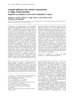
Typical cross sections are shown in Figures 1.3 and 1.4 (Figure 1.4 is a negative of
Figure 1.3 and shows the striations more clearly). Photomicrographs have also been
shown in connection with meeting the outdoor performance application standards for
insulated cables by Patch [5], whilst Lee and Borke [6] have quite recently included
mixing effects among factors affecting the performance of carbon black masterbatches
in wire and cable applications.
10
Mixing in Single Screw Extrusion
Figure 1.3 Pipe cross section photomicrograph without breaker plate.
(Photograph taken by D.I. James. ©Rapra Technology)
Figure 1.4 Pipe cross section photomicrograph (negative) with breaker plate.
(Photograph taken by D.I. James. ©Rapra Technology)
11
The Need for Good Mixing in Single Screw Extrusion
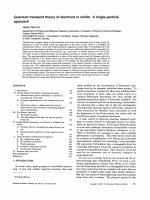
1.2.2 Blow Moulded Bottles
Figure 1.5 shows a blow moulded bottle which formerly contained a laundry
softener. Viewed through the bottle’s neck there are stripes of poorly distributed
blue masterbatch. This indicates that the blow moulder had ‘given away’ expensive
colour masterbatch. If good distributive mixing had been achieved by the extruder,
less masterbatch could have been used and the bottle more profitable. Masterbatch
mixing appears to be a particular problem with blow moulded containers in high
molecular weight polyethylene [7, 8].
Figure 1.5 Blow moulded bottle. (a) complete bottle, (b) Inside view through neck
showing masterbatch stripes.
(a)
(b)
12
Mixing in Single Screw Extrusion
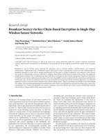
1.2.3 Chalk Filled Polypropylene Pipe
Rigid pipe was required, extruded as a blend of polypropylene pellets and 40 wt%
surface treated Calcium carbonate filler as a substitute for rigid polyvinylchloride (PVC).
The speckled pipe sample (Figure 1.6) clearly shows that dispersive mixing of fine
powders is difficult or impossible with a single screw extruder under normal conditions.
A pipe with the same composition was produced using a very high concentration of
chalk masterbatch prepared in a twin screw extruder and let down to 40 wt% chalk in
the single screw extruder used previously. In this case the dispersion (and distribution)
was good, but the two stage process would have been uneconomic.
Figure 1.6 Polypropylene pipe with (a) undispersed agglomerated filler;
(b) produced using a two-stage process
(a)
(b)
13
The Need for Good Mixing in Single Screw Extrusion
1.2.4 Blown Film
Film blowing will show up problems of poor masterbatch distribution even more than
blow mouldings and will also show the presence of agglomerates due to substandard
pigment dispersion. This technique is sometimes used on a laboratory scale for pigment
masterbatch quality control.
The addition of a mixing element of the types described in Chapter 9 will often enable
the extruder to produce good striation free film from the same polymer and colour
masterbatch blend which otherwise produces film with coloured stripes.
1.2.5 Industrial Blow Mouldings
Blow moulded containers forming part of a machine incorporated a flame retardant
masterbatch in order to meet a UL94 spread of flame requirement which used test
pieces 12.7 mm wide by 150 mm long. The results for individual test pieces ranged
from immediate flame extinction to burning the full length of the test piece: most results
being scattered between these two extremes. Microscopy examination revealed that
the scatter of results was caused by the flame retarding masterbatch being distributed
in bands similar to those for bottles described in Section 1.22. It appears that the
blowing process exaggerates this effect.
Inadequate mixing of flame retardant masterbatches has also resulted in corner
cracking of large blow moulded drums used for transporting chemicals when drop
tested. Following laboratory trials to evaluate potential mixing devices a mixer was
retrofitted as a screw extension which solved the problem.
1.2.6 Production Scrap Re-use
Distributive mixing can influence production economics in situations other than the
incorporation of masterbatches and additives. In the production of thermoformed
food packaging containers, thin sheet edge trim and skeletal scrap (a continuous
sheet full of holes following separation of formed containers such as round yoghurt
pots) can represent 40% of the original sheet. It is essential to the economics of the
process that this scrap is recycled. In an example, a five layer barrier sheet consisting
of a barrier polymer layer with adjoining adhesive and polyolefin layers on either side
had an additional layer of ‘buried scrap’. Inadequate homogenising of the separate
components of the scrap layer resulted in unacceptable ripples in the thermoformed
pots. Following laboratory extrusion trials with the granulated scrap, a mixing device
was fitted to the scrap layer production extruder which solved the problem.
14
Mixing in Single Screw Extrusion
1.2.7 Agglomerates and Gels in Thin Extrusions
The presence of undispersed particle clusters in thin sheet and film can result in holes
or thin lines prone to splitting in use. Normally an agglomerate will be found at the
edge of the hole and at, or near, the start of the thin section line. These particles may
be additive agglomerates, gels, or contaminants. The agglomerates should not be
present in the feed material. Gels may result from a need to locate ‘hang-up’ areas in
the machinery to prevent oxidation or if a melting problem it might be dealt with by
dispersive mixing. In practice, this is difficult (see Section 14.11).
1.2.7.1 Thin Plasticised PVC
A very thin flexible PVC extrusion proved unsatisfactory in service due to porosity.
A microscopic examination showed that the holes had been generated by pigment
agglomerates, each hole having an agglomerate at its edge. Initially the extruder had
been blamed for a lack of mixing, but the remedy was entirely with the compound
supplier to ensure the PVC compound was free from agglomerates in the first place.
It was important in this case to establish that the problem was caused by pigment,
filler, or stabiliser and not degraded PVC or contaminants such as dirt off the floor
following repacking a split bag by a carrier.
The use of fine wire mesh screens at the barrel exit by the product extruder may
suffice to catch a very low concentration of agglomerates, paper wrapping, and ball
point pen tips, but might not be used with PVC in case of stagnation causing thermal
decomposition.
1.2.7.2 Silage Wrap Splitting in Use
Following the rotting of silage, it was found that considerable amounts of film had
split, allowing rain to penetrate the silage during outdoor storage. Examination
showed particles existing at the start of each slit, which appeared to be carbon black
agglomerates. However, infra-red analysis showed the particles to be crosslinked gels,
most likely caused by thermal oxidation during the extrusion process.
1.2.7.3 Holes in Silage Wrap Film During Film Blowing
Holes caused by gels appeared during film blowing of linear low-density polyethylene
silage wrap film. The gels appeared to melt when film samples were heated on a
microscope hot stage, but infra-red analysis showed the observed gels were clusters of
15
The Need for Good Mixing in Single Screw Extrusion
finely divided partially crosslinked particles. Suspecting that the problem was caused
by oxidative crosslinking in the extrusion equipment, an antioxidant masterbatch was
blended with the natural polymer pellets and a liquid antioxidant was added to the
polybutene tackifier being pumped into the extruder. Although this increased materials
cost, it transformed the film quality. In addition to eliminating formation of large gels
previously causing the holes, the large number of smaller gels was also eliminated.
In these two silage wrap film examples, the problems lay with the formation of gels
which ideally would be destroyed by good dispersive mixing. However, when such
gels consist of partially crosslinked rubbery unmelted oxidised particles, the solution
widely used in blown film extrusion is to filter out the particles using fine mesh screens,
although smaller gels may deform like soft rubber balls, squeezing through the screen
apertures and recovering their shape after the screen. Unfortunately the gels may
develop after the screens both in the die or more likely as a result of co-extrusion
feed pipes. These may be long with ‘dog legs’, corners, and no chrome or polished
surfaces in difficult to access areas.
The answer to the problem of gels is to avoid their formation in the first place if at
all possible (see Chapter 14).
1.2.8 Transparent Polycaprolactone/SAN Blends
Polycaprolactone, which is widely used in medical applications, can be blended with
a number of polymers such as styrene-acrylonitrile (SAN), PVC, and polycarbonate.
In this example a polymer blend of polycaprolactone with a high nitrile SAN was
expected to give a transparent extruded sheet which was thermoformable in hot water.
Suitable thermoforming properties and adequate transparency had been achieved with
35 wt% polycaprolactone blended with 65 wt% SAN using small laboratory samples
prepared in a torque rheometer. Unfortunately, strips extruded from a pellet blend
using a 25 mm laboratory extruder were white, cloudy and not transparent.
Following work with an independently driven mixer, subsequent trials with a 38 mm
extruder having a cavity transfer mixer attached as a screw and barrel extension gave
acceptable transparency.
1.2.9 Decorative Wood Grain Effects
A lack of distributive mixing can be exploited, providing it is controlled, to give
decorative patterns on the surface. This is normally achieved using blends of
different coloured pellets which also differ in viscosity. The patterns are the result of
16
Mixing in Single Screw Extrusion
a combination of the melting process producing coloured ribbons and viscous flow
in the die with drag at die surfaces producing coloured striations as described in later
chapters. This effect can be exploited to provide extruded wood grain effect plastic
profiles for office furniture, shop fittings, etc. Special masterbatches are available for
such applications. This continues a long history in which coloured blends of cellulosic
plastics were developed for spectacle frames, pen barrels and combs: processes which
originally exploited the poor mixing performances of the short barreled extruders
and plunger injection moulding machines of the past.
References
1. M. Tresca in Iron and Steel Manufacture, Ed., F. Kohn, William Mackenzie,
London, UK, 1868.
2. BS EN 13244-1, Plastics Piping Systems for Buried and Above-Ground
Pressure Syetems for Water for General Purposes, Drainage and Sewage –
Polyethylene (PE) – Part 1: General, 2003.
3. BS EN 13244-2, Plastics Piping Systems for Buried and Above-Ground
Pressure Systems for Water for General Purposes, Drainage and Sewage –
Polyethylene (PE) – Part 2: Pipes, 2003.
4. BS EN 13244-5, Plastics Piping Systems for Buried and Above-Ground
Pressure Systems for Water for General Purposes, Drainage and Sewage –
Polyethylene (PE) – Part 5: Fitness for Purpose of the System, 2003.
5. R. Patch, Kunststoffe, 1975, 65, 2, 89.
6. C.D. Lee and J.S. Borke in Proceedings of the 62nd Annual SPE Conference –
ANTEC 2004, Chicago, IL, USA, 2004, p.288.
7. D. Boes, Kunststoffe, 1974, 64, 11, 641.
8. G. Martin, Kunststofftechnik, 1972, 11, 12, 329.