- Trang chủ >>
- Khoa Học Tự Nhiên >>
- Vật lý
Single electron effects in highly doped polysilicon nanowires
Bạn đang xem bản rút gọn của tài liệu. Xem và tải ngay bản đầy đủ của tài liệu tại đây (268.98 KB, 5 trang )
Physica E 15 (2002) 60 – 64
www.elsevier.com/locate/physe
Single-electron eects in highly doped polysilicon nanowires
A. Tilke
∗ ;1
R.H. Blick, H. Lorenz, J.P. Kotthaus
Center for NanoScience and Sektion Physik, LMU Munich, Geschwister-Scholl-Platz 1, 80539 M
unchen, Germany
Received 13 October 2000; received in revised form 29 November 2001; accepted 18 January 2002
Abstract
We investigate silicon-based single-electron transistors in thin layers of highly doped recrystallized amorphous silicon.
After rapid thermal annealing polysilicon grains have been found with sizes of about 25 nm acting as electron islands.
Applying high-resolution electron-beam lithography we have fabricated nanowires with width down to about 10 nm in the
polycrystalline silicon ÿlms. Single-electron eects in the non-linear source–drain characteristics up to temperatures of about
25 K have been observed. ? 2002 Elsevier Science B.V. All rights reserved.
PACS: 81.05.Gc; 81.15.Cd; 81.40.−z; 85.35.Gv
Keywords: Single-electron devices; amorphous and polycrystalline silicon; deposition by sputtering
1. Introduction
Recently, single-electron transistors (SET) realized
in silicon-on-insulator (SOI) were found to exhibit
Coulomb blockade eects up to room temperature
[1–3]. Both, SETs embedded in inversion-ÿeld ef-
fect structures [1–4], as well as highly doped silicon
nanowires where a gate voltage can change the chem-
ical potential inside the wire were used [5 –8]. How-
ever, in particular in highly doped SOI-nanostructures
the origin of the electron island formation is not yet
fully understood. Doping uctuations as well as seg-
regation eects can be made responsible to cause a
serial arrangement of multiple tunnel junctions (MTJ)
inside the nanostructures. Irvine et al. [9] ÿrst used
∗
Corresponding author.
E-mail address:
(A. Tilke).
1
Permanent address: Inÿneon Technologies, Konigsbr
ucker Str.
180, 01099 Dresden, Germany.
highly doped polycrystalline silicon ÿlms to fabricate
SET-devices. Also amorphous, recrystallized silicon
was used by this group [10]. Since the size of the
polysilicon grains can be adjusted during an annealing
step to be about 20 nm, a controllable formation of
multiple dot structures in a polysilicon nanowire can
be achieved. Yano et al. [11] observed single-electron
eects in ultrathin polycrystalline wires embedded in
a metal–oxide–silicon ÿeld eect structure. Electron
transport turned out to be dominated by thermal emis-
sion. Thus, making the wire highly conductive by
applying a positive gate voltage, an Arrhenius type
behaviour of the conductance was observed. Also the
use of highly doped polycrystalline silicon ÿlms as
an application for oating dot memory has attracted
much interest in the last few years [12–14].
Here, we present results on Coulomb blockade ex-
periments performed on highly As-doped nanowires
structured in sputtered amorphous and recrystallized
silicon ÿlms. In addition, we investigate the electronic
properties of these nanowires in high magnetic ÿelds
up to B = 12 T. Since sputtering of amorphous silicon
1386-9477/02/$ - see front matter ? 2002 Elsevier Science B.V. All rights reserved.
PII: S 1386-9477(02)00451-4
A. Tilke et al. / Physica E 15 (2002) 60 – 64 61
(a-Si) in combination with rapid thermal annealing
(RTA) is a less expensive fabrication method than the
use of high quality SOI-material to form highly doped
SET-structures, this fabrication process is of impor-
tance for future device applications.
2. Fabrication
On a standard n-type silicon wafer covered with a
500 nm thick thermal oxide a 40 nm thick a-Si layer
was deposited by radio frequency (RF) sputtering in
an Ar-plasma [15]. In order to produce a-Si ÿlms with
highest possible ÿlm qualities the variation of dierent
sputtering parameters such as RF-power, Ar-pressure
and substrate bias was investigated. The qualities of
these dierent ÿlms were then examined both by mea-
suring the surface roughness with an atomic force
microscope (AFM), as well as by investigating the re-
fraction index by optical ellipsometry. The optimum
sputtering conditions as judged from optical density
and surface morphology lead to a sputtering rate of
6:6nm=min.
Subsequently, the a-Si-ÿlms were highly n-doped
by ion-implantation of As with a dose of 2×10
15
cm
−2
at an ion energy of 20 keV. These parameters led to
a nominal doping level of these a-SOI-ÿlms of about
4×10
20
cm
−3
. High-temperature annealing performed
in a RTA chamber served both, to activate the dopant
atoms [16] as well as to recrystallize the a-Si layer
[17,18] to form a polycrystalline silicon (poly-Si) ÿlm.
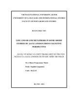
In Fig. 1(a) the AFM-image of the surfaces of an
ion-implanted but not yet annealed a-Si ÿlm is shown.
Fig. 1(b) shows the surface annealed for 30 s at a
temperature of 1000
◦
C. Nanometer sized polysilicon
grains are clearly visible. An average diameter of these
grains is determined to be about 25 nm. The grain size
increases both with longer annealing time as well as
with higher annealing temperature. Since these poly-Si
grains are intended to serve as single-electron islands
in laterally structured nanowires, the annealing time
has to be very short and properly controlled in or-
der to guarantee small grain sizes. On the other hand,
both electronic activation of the dopant atoms as well
as the electronic quality of the nanocrystals increases
with higher annealing temperature. Therefore, in our
investigations we found an annealing duration of 30 s
at a temperature of 1000
◦
C to be a suitable compro-
mise between small grain size and acceptable elec-
tronic qualities.
The highly doped poly-Si ÿlms were then later-
ally patterned by low-energy electron-beam litho-
graphy using the negative electron resist calixarene
[19]. Reactive ion etching with CF
4
and evaporation
of contact-pads completed the fabrication process.
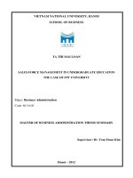
Fig. 2 shows a scanning electron-beam micrograph of
one of our devices. In-plane sidegates were integrated
in the poly-Si ÿlm in order to permit electrostatic
control of the nanowire. Usually, single-electron
structures in SOI-ÿlms can be passivated and fur-
ther shrunk by thermal growth of a thin gate oxide
[1]. In order to avoid preferential oxidation at the
grain boundaries of the poly-Si nanowire [20] we
abandoned this fabrication technique for the devices
presented here. Due to this lack of a gate oxide only
the sidegates were available to control the conduc-
tance of the wire. The samples were then mounted
into a chip-carrier, attached onto a sample holder and
characterized in the chamber of a variable tempera-
ture insert (VTI) allowing temperatures in the range
between 1.5 and 250 K. The VTI was surrounded by
a superconducting solenoid providing magnetic ÿelds
up to 12 T.
3. Measurements
We used standard lock-in techniques to mea-
sure the conductance g =dI
D
=dV
SD
—with I
D
the
drain current—of the nanowires as a function of
applied source–drain bias V
SD
, of a sidegate volt-
age V
SG
, of temperature T and of the magnetic
ÿeld B . Fig. 3(a) shows the conductance of a
25 nm wide, 40 nm high and 500 nm long poly-Si
nanowire as a function of temperature. At low T
a conductance dip around V
SD
= 0 V is visible
that can be attributed to the formation of multi-
ple tunnel junctions (MTJ) formed in the poly-
crystalline structure [5,9]. This conduction dip at
zero source–drain bias vanishes at temperatures of
about 24 K. Applying a negative sidegate-voltage
to the in-plane gate leads to a reduced conduc-
tance of the nanostructure. Nevertheless, we cannot
deplete the device suciently for ensuring only
weak electronic coupling between neighbouring sili-
con grains. Therefore, we are not able to observe
62 A. Tilke et al. / Physica E 15 (2002) 60 – 64
Fig. 1. (a) AFM-micrograph of a sputtered and ion-implanted a-Si ÿlm on an oxidized silicon wafer. The surface roughness is similar to
that of the substrate-wafer. In (b) an AFM-scan of a recrystallized polysilicon ÿlm is shown. Polysilicon grains with diameters of about
25 nm are found (inset).
a conductance minimum at g = 0 as a function of
V
SD
and also only very weak conductance oscilla-
tions as a function of V
SG
in contrast to monocrys-
talline, highly doped, fully depleted silicon nanowires
[5,7].
In the inset of Fig. 3(a) the temperature depen-
dence of g at V
SD
= 0 V with an AC-sensing voltage
of V
sd
= 100 V is shown. In contrast to the observa-
tion in Ref. [11] no activation type behaviour of the
conductance can be found. In our structures the grain
A. Tilke et al. / Physica E 15 (2002) 60 – 64 63
Fig. 2. SEM-micrograph of a 11 nm wide nanowire in a 50 nm thin polysilicon ÿlm deÿned by low-energy electron-beam lithography.
boundaries are saturated with As in contrast to the
undoped polysilicon ÿlms, as stated in Ref. [11]. Pre-
sumably, thermal emission can therefore not be ob-
served in the highly doped wires.
The number N of the tunnel junctions inside the
nanowire can be estimated from the temperature de-
pendence of the full-width at half-maximum (FWHM)
of the conductance dip around V
SD
= 0 V [21]. From
the traces shown in Fig. 3(a) we derive N ≈ 12 for the
polycrystalline wire discussed here. Attributing one
tunnel junction to one polysilicon grain inside the wire
with a length of 250 nm we obtain a mean grain size
of about 21 nm. This is in very good agreement with
the AFM measurements shown in Fig. 1.
The magnetic ÿeld dependence of the conductance
shown in Fig. 3(b) displays a decrease of the conduc-
tance dip but no complete reduction up to B ≈ 6T.
This ÿnding indicates a clear B-dependence of the
eective tunneling barriers. Since this dependence
turns out to be weak the conÿning potential in-
side the silicon grains can be assumed to be rather
strong. Strikingly, the conductance minimum be-
comes deeper when increasing the magnetic ÿeld
further and decreases again at B¿11 T. Deriving
the Fermi-wavelength
F
from the electron density
one ÿnds
F
≈ 4 nm for a crystalline ÿlm. Taking
that value for a simple approximation, one gets the
classical cyclotron radius r
B
for electrons in high
magnetic ÿeld B perpendicular to the sample sur-
face r
B
≈ 1 m=B [T]. The second minimum in the
conductance at zero bias around B ≈ 10 T there-
fore corresponds to r
B
≈ 100 nm. Taking into ac-
count the crude simpliÿcations in this evaluation, this
value is comparable to the extensions of the poly-Si
grains and is therefore ascribed to stronger elec-
tron conÿnement inside the grains at high magnetic
ÿelds.
4. Summary
In summary, we have fabricated single-electron de-
vices out of highly doped, polycrystalline silicon ÿlms.
These ÿlms were deposited on oxidized, standard sili-
con wafers by sputtering, doped by ion-implantation
and recrystallized by RTA. The SET-structures were
deÿned by high-resolution electron-beam lithogra-
phy and dry-etching. Single-electron eects have
been found up to temperatures of about 24 K. The
non-linear source–drain characteristics displays an
only weak dependence of magnetic ÿelds up to B ≈
12 T indicating a rather hard conÿnement potential
inside the poly-Si grains.
64 A. Tilke et al. / Physica E 15 (2002) 60 – 64
Fig. 3. (a) Temperature dependence of the non-linear source–drain
characteristics of a 25 nm wide, 40 nm high and 500 nm long
poly-Si nanowire. The inset shows the temperature dependence
of the conductance at zero bias V
SD
= 0 V. (b) Magnetic ÿeld
dependence of the conductance at T = 2 K. A second minimum
around B ≈ 10 T is visible.
Acknowledgements
We would like to thank F. Simmel for useful
discussions and A. Kriele and S. Manus for technical
support. We acknowledge ÿnancial support from the
BMBF (contract number 01M2413C6).
References
[1] L. Zhuang, L. Guo, S.Y. Chou, Appl. Phys. Lett. 72 (1998)
1205.
[2] K. Kurihara, H. Namatsu, M. Nagase, T. Makino,
Microelectron. Eng. 35 (1997) 261.
[3] H. Ishikuro, T. Hiramoto, Appl. Phys. Lett. 71 (1997)
3691.
[4] A. Tilke, R.H. Blick, H. Lorenz, J.P. Kotthaus, J. Appl. Phys.
90 (2001) 942.
[5] R.A. Smith, H. Ahmed, J. Appl. Phys. 81 (1997) 2699.
[6] A. Tilke, R.H. Blick, H. Lorenz, J.P. Kotthaus, D.A. Wharam,
Appl. Phys. Lett. 75 (1999) 3904.
[7] A. Tilke, R.H. Blick, H. Lorenz, J.P. Kotthaus, J. Appl. Phys.
89 (2001) 8159.
[8] T. Sakamoto, H. Kawaura, T. Baba, Appl. Phys. Lett. 72
(795) 1998.
[9] A.C. Irvine, Z.A.K. Durani, H. Ahmed, Appl. Phys. Lett. 73
(1998) 1113.
[10] V. Ng, H. Ahmed, T. Shimada, Appl. Phys. Lett. 73 (1998)
972.
[11] K. Yano, T. Ishii, T. Hiramoto, T. Kobayashi, F. Murai,
K. Seki, Appl. Phys. Lett. 67 (1995) 828.
[12] L. Guo, E. Leobandung, L. Zhuang, S. Chou, J. Vac. Sci.
Technol. B 15 (1997) 2840.
[13] N. Takahashi, H. Ishikuro, T. Hiramoto, Appl. Phys. Lett. 76
(2000) 209.
[14] A.M. Rudin, L.J. Guo, L.I. Glazman, S.Y. Chou, Appl. Phys.
Lett. 73 (1998) 3429.
[15] F.S. Becker, H. Oppolzer, I. Weitzel, H. Eicherm
uller,
H. Schaber, J. Appl. Phys. 56 (1984) 1233.
[16] G.S. Sunatori, A.A. Berezin, J. Appl. Phys. 55 (1984)
3125.
[17] R. Kakkad, J. Smith, W.S. Lau, S.J. Fonash, J. Appl. Phys.
65 (1989) 2069.
[18] Y.T. Kim, H.J. Yoo, C.H. Jun, W.I. Jang, S.H. Kim, J. Vac.
Sci. Technol. A 7 (1989) 796.
[19] A. Tilke, M. Vogel, A. Kriele, F. Simmel, R.H. Blick,
H. Lorenz, D.A. Wharam, J.P. Kotthaus, J. Vac. Sci. Technol.
B 17 (1999) 1594.
[20] J.C. Bravman, R. Sinclair, Thin Solid Films 104 (1983)
153.
[21] J.P. Pekola, J.P. Kauppinen, M.A. Paalanen, Phys. Rev. Lett.
73 (1994) 2903;
J.P. Pekola, L.J. Taskinen, Sh. Farhangfar, Appl. Phys. Lett.
76 (2000) 3747.