filters and filtration handbook, 5th edition
Bạn đang xem bản rút gọn của tài liệu. Xem và tải ngay bản đầy đủ của tài liệu tại đây (6.42 MB, 536 trang )
Filters and Filtration
Handbook
This page intentionally left blank
Filters and Filtration
Handbook
Fifth Edition
Ken Sutherland
AMSTERDAM • BOSTON • HIEDELBERG • LONDON
NEWYORK • OXFORD • PARIS • SAN DIEGO
SAN FRANCISCO • SINGAPORE •
SYDNEY • TOKYO
Butterworth-Heinemann is an imprint of Elsevier
Butterworth-Heinemann is an imprint of Elsevier
Linacre House, Jordan Hill, Oxford OX2 8DP, UK
30 Corporate Drive, Suite 400, Burlington, MA 01803, USA
Fifth edition 2008
Copyright © 2008 Elsevier Ltd. All rights reserved
No part of this publication may be reproduced, stored in a retrieval system or
transmitted in any form or by any means electronic, mechanical, photocopying, recording
or otherwise without the prior written permission of the publisher
Permissions may be sought directly from Elsevier ’ s Science and Technology Rights
Department in Oxford, UK: phone (+44) (0) 1865 843830; fax (+44) (0) 1865 853333;
email: Alternatively you can submit your request online by
visiting the Elsevier web site at , and selecting
Obtaining permission to use Elsevier material
Notice
No responsibility is assumed by the publisher for any injury and/or damage to persons
or property as a matter of products liability, negligence or otherwise, or from any use or
operation of any methods, products, instructions or ideas contained in the material herein.
British Library Cataloguing in Publication Data
A catalogue record for this book is available from the British Library
Library of Congress Cataloguing in Publication Data
A catalogue record for this book is available from the Library of Congress
ISBN: 978-1-8561-7464-0
For information on all Elsevier Limited publications visit our
web site at
Typeset by Charon Tec Ltd (A Macmillan Company), Chennai, India
www.charontec.com
Printed and bound in Hungary
08 0910111210 987654321
CONTENTS
Preface viii
Acknowledgements to Illustrations x
SECTION 1 Basic Principles 1
1A. Filtration and Separation 1
1B. Contaminants 7
1C. Surface and Depth Filtration 14
1D. Filter Ratings 20
1E. Filter Tests 28
SECTION 2 Filter Media 41
2A. Introduction 41
2B. Absorbent, Adsorbent and Biological Filter Media 44
2C. Paper and Fabrics 46
2D. Woven Wire and Screens 66
2E. Constructed Filter Cartridges 82
2F. Membranes 85
2G. Packed Beds 92
SECTION 3 Types of Filter 97
3A. Introduction 97
3B. Strainers 100
3C. Screens 107
3D. Nutsche Filters 114
3E. Tipping Pan and Table Filters 115
3F. Rotary Drum Filters 116
3G. Rotary Disc Filters 128
3 H. Horizontal Belt Filters 132
3I. Centrifugal Filters 136
3J. Pad and Panel Filters 146
3K. Bag, Pocket and Candle Filters 150
3L. Cartridge Filters 158
3M. Backfl ushing and Self-cleaning Filters 172
3N. Leaf and Plate Filters 176
3O. Filter Presses 183
3P. Belt Presses 189
3Q. Variable Volume Filters 190
3R. Screw Presses 192
3S. Cross-fl ow and Membrane Systems 192
3T. Magnetic Filters 198
3U. Electrically Aided Filters 204
3V. Deep-Bed Filters 205
SECTION 4 Liquid Filtration 209
4A. Introduction 209
4B. Bulk Water Filters 210
4C. Drinking Water Filters 224
4D. Process Water Treatment 231
4E. Municipal and Industrial Wastewater Treatment 238
4F. Process Filters 247
4G. Surface Treatment Chemicals 267
4H. Metal Working Fluids 276
4I. Dewatering and Fuel Treatment 290
SECTION 5 Oils and Hydraulic Systems 295
5A. Introduction 295
5B. Engine Filters 295
5C. Oil–water Separators 312
5D. Oil Cleaning 320
5E. Hydraulic Systems 331
SECTION 6 Gas Filtration 369
6A. Introduction 369
6B. Indoor Air Quality 370
6C. Fume and Vapour Emissions 391
6D. Dust Collectors 402
6E. Machine Air Intake Filters 416
6F. Vehicle Cabin Filters 421
6G. Compressed Air Filtration 422
6H. Pneumatic Systems 435
6I. Sterile Air and Gas Filters 437
6J. Respiratory Air Filters 444
CONTENTS
vi
SECTION 7 Other Types of Separation Equipment 451
7A. Introduction 451
7B. Sedimenting Separators 454
7C. Centrifuges 458
7D. Cyclones and Hydrocyclones 473
7E. Coalescers 474
7F. Wet and Dry Scrubbers 478
7G. Mist Eliminators 481
7H. Electrostatic Precipitators 485
SECTION 8 Filter Selection 489
8A. Introduction 489
8B. Filter Selection 489
8C. Reference Standards 505
Index 507
CONTENTS
vii
viii
PREFACE
In the ever-changing world of fi ltration, one of the constants for many years has
been the availability in print of the engineer ’ s reference book, the Filters and
Filtration Handbook , as, in the words of the Preface to the Fourth Edition, ‘ a fi rst
source of reference and practical guide to fi ltration and separation products and
their applications ’ .
It did not have too promising a start: I have a copy of the First Edition, and a
review of it by ‘ an authority on solid-liquid separation ’ , which begins: ‘ At £48,
this must be the joke book of the decade, since it really cannot be taken seriously ’ .
Derek ’ s harsh words (for it was, indeed, Derek Purchas who wrote that scathing
review) did not prevail, and a change fi rst of author, to Christopher Dickenson, and
then of publisher, to Elsevier, has seen it successfully through three more editions,
some of which were reprinted.
Which brings us to this Fifth Edition, which may justifi ably be considered the
Silver Jubilee edition, since it is 25 years since the First Edition was published.
With Christopher now retired, the publishers have brought in a new author, tasked
with producing a Handbook for the new millennium.
Filtration is a curiously mixed process, with some very old technologies and
some very new ones. Much that is old is also unchanged, but not all of it, while
some of the new technology would hardly have been noticed for the First Edition.
One of the major changes that the quarter-century has brought is the controlling
infl uence of legislation enacted nationally or internationally and covering a wide
range of end-use industry sectors, primarily infl uencing their environmental impact,
all the way from extraction of raw materials through to use of the fi nished product.
Another major driving force for change in the fi ltration business comes from the
end-users, whose increasingly precise businesses – whether in making semiconduc-
tors or producing drinking water, in a machine shop or making beer – continually
demand fi ner and fi ner degrees of fi ltration. This driver affects the fi lter medium
more than the fi lter itself, but there is quite a bit of change to be seen in the whole
fi lter unit to accommodate these media changes.
It must be emphasized here that this book is not a textbook on fi ltration – guid-
ance as to suitable texts will be made in the appropriate place. Nor is it a handbook
of process fi ltration, where the separated solids are as important as the fi ltered fl uid.
This handbook deals largely with the removal of solid contaminants from a fl ow of
fl uid, liquid or gas, where the degree of contamination is relatively low – but still
unacceptable. It thus covers service and process applications where a pure fl uid is
the required result of the fi ltration, and the separated solids are unwanted and are
usually discarded. Mention is still made of solids recovery fi ltration, but only suf-
fi ciently as to put the rest of the coverage in context. In this same spirit of thor-
ough coverage, mention is made of physical separations by other means, mainly
sedimentation.
This, then, is a book about the purifi cation of fl uids, primarily by means of fi ltra-
tion. As well as emphasizing this main purpose of the book, the opportunity has
been taken in this revised edition to restructure the book in terms of the section
order, although most of the topics covered by previous editions are continued in
this edition. Information has been updated where necessary, but the book still con-
centrates on the technology of fl uid purifi cation. For a copy of the Filtration and
Separation magazine, which also produces an annual Buyer’s Guide for subscribed
readers, I would refer you to http://www.fi ltsep.com.
It is hoped that this will be a confi dent step in the book ’ s progress into its second
quarter-century.
Ken Sutherland
PREFACE
ix
x
ACKNOWLEDGEMENTS TO
ILLUSTRATIONS
2.2 Carlson Filtration
2.4 Esters – Filtertechnik
2.5 Porex Technologies
2.6 Porex Technologies
2.7 Bekaert Fibre Technologies
2.9 Potter and Soar
2.10 Potter and Soar
2.11 Potter and Soar
2.12 Potter and Soar
2.13 Potter and Soar
2.20 Memtech (UK) Ltd
2.21 Flowtech
2.23 US Filter Corp
2.25 Memtech (UK) Ltd
3.1 Firtop Filters, Barton
Hydraulic Engineering Ltd
3.2 Strainwell
3.4 Tate (Guardian) Andale
3.6 Airpel Filtration Ltd
3.8 Jones and Atwood
3.9 Johnson Filtration Systems
3.10 Contra-Shear
3.11 Houston Well Systems
3.12 Eriez
3.13 Eriez
3.14 Krauss-MAFFEI
3.15 EIMCO
3.16 EIMCO
3.17 EIMCO
3.18 Krauss-MAFFEI
3.19 EIMCO
3.20 EIMCO
3.21 EIMCO
3.22 EIMCO
3.23 Joy Processing Equipment
3.24 Alfa Laval
3.25 Outokumpu
3.26 Hodge Stetfi eld Ltd
3.27 Fractionment SA
3.28 Panneuis
3.29 Western States Machine Company
3.30 Alfa Laval
3.31 Alfa Laval
3.32 Alfa Laval
3.33 Alfa Laval
3.34 Krauss-MAFFEI
3.35 Krauss-MAFFEI
3.36 Krauss-MAFFEI
3.37 Krauss-MAFFEI
3.38 Vokes
3.41 Loeffl er Filter Technik GmbH
3.42 Loeffl er Filter Technik GmbH
3.43 Hayward Industrial Products Inc.
3.46 AAF International BU
ACKNOWLEDGEMENTS TO ILLUSTRATIONS
3.47 Harnisch GmbH
3.49 N. Lancashire
3.50 Harmsco
3.51 Osmonics Inc.
3.52 3 M Filtration Products
3.53 Accumatic Engineering Ltd
3.54 Purolator Products Co.
3.55 Gneu
3.57 Serfi lco
3.58 Cuno Filter Systems
3.60 Kalsep
3.61 LFC Lochem BV
3.62 Celite Corp
3.63 Celite Corp
3.64 Sparkler Filters
3.65 Celite Corp
3.66 Sparkler Filters
3.67 Celite Corp
3.68 BHS
3.69 VELO SpA
3.70 Edwards and Jones
3.71 Ritlerhaus and Blecher
3.72 Netzch Filtrationtechnik
3.73 Larox Oy
3.75 VC Filters International Ltd
3.77 Ceramem Corp
3.78 PCI Membrane Systems
3.80 Philips
3.82 Philips
3.83 Philips
3.85 Faudi Feinbau GmbH
3.86 Eriez Magnetics
4.1 Axel Johnson Engineering
4.2 General Waters SpA
4.3 Trident Wheelabrator
Technologies
4.4 ELGA Ltd
4.7 AMEG UK
4.8 Endless Energy Ltd
4.10 Weir Westgarth Ltd
4.12 Corning
4.14 BWK
4.15 Ecolochem International
4.16 Ametek
4.17 IMI Norgren
4.18 IMI Norgren
4.19 Gütling
4.20 Gütling
4.22 Infi lco Degremont Inc.
4.23 Alfa Laval
4.24 Gütling
4.25 Cuno
4.26 Outomec Oy
4.27 Lochem BV
4.28 Cuno
4.30 Western States Machine Co.
4.31 Plenty Filters
4.33 La Carbone-Lorraine
4.34 Membrex USA
4.35 Durr GmbH
4.36 Faudi Filter System
4.38 Selfi lco
4.40 Filtermist
4.41 Alfa Laval
4.42 Hydrafl ow Inc.
5.3 Lucas Industries
5.4 Racor/Parker Filtration
5.5 Mann & Hummel
5.6 Josef Heimach GmbH & Co.
5.13 Techniquip Ltd
5.14 Hodge Stetfi eld Ltd
5.16 Como Industrial Equipment
5.17 Alfa Laval
5.18 Alfa Laval
5.19 Pall Group
5.20 Alfa Laval
5.21 KHD Humboldt Wedag
5.22 KHD Humboldt Wedag
5.24 Pall Group
5.25 Pall Group
5.28 Thermal Control Co.
5.29 Pall Europe Ltd
6.3 AAF International BU
6.4 AAF International BU
6.5 Expamet
6.6 Penair Filtration
xi
6.8 Vokes
6.9 AAF
6.11 Donaldson
6.18 Neu
6.19 Filtermist Co.
6.20 Anguil
6.21 Anguil
6.22 P & S Filtration
6.25 AAF Snyder General
6.26 Flex-Kleen
6.28 Airmaster Engineering
6.29 Procedair SA
6.31 Dalmatic
6.33 Purolator
6.37 AAF
6.38 AAF
6.40 Zander
6.41 Beach Filters
6.42 Zander
6.45 Zander
6.51 Ultrafi lter GmbH
7.6 Dorr Oliver
7.7 Alfa Laval
7.8 Westfalia Separator
7.10 Alfa Laval
7.11 Bird Machine Company
7.12 Eisenwerke Kaiserlautern GmbH
7.13 Myson International
7.14 Vokes Ltd
7.15 Eisenwerke Kaiserlautern GmbH
7.16 Stein Atkinson Stordy
7.17 Monsanto Enviro-Chem
Systems Inc.
7.18 Koch International
7.19 Myson International
7.20 Eisenwerke Kaiserlautern GmbH
xii
ACKNOWLEDGEMENTS TO ILLUSTRATIONS
1
BASIC PRINCIPLES
SECTION CONTENTS
1A. Filtration and separation
1B. Contaminants
1C. Surface and depth fi ltration
1D. Filter ratings
1E. Filter tests
1A. FILTRATION AND SEPARATION
A book entitled Filters and Filtration Handbook is clearly stating its purpose in
those words, but the primary topic – fl uid purifi cation free of contaminants by
means of mechanical separation processes – requires a somewhat broader coverage
than those words imply. The title of this chapter suggests that broader coverage,
even if it is a little confusing, because fi ltration is one form of separation. The title
is, in fact, shorthand for the more cumbersome phrase: ‘ fi ltration and other related
forms of separation ’ , and has been used in that way for over 40 years, as the title of
a leading magazine in the industry proclaims. Throughout this book the term ‘ fi ltra-
tion ’ should thus be read as to imply that broader term (unless the context suggests
the narrower defi nition).
So it is perhaps as well to start with some sort of defi nition of these terms, in the
context of this Handbook. Filtration specifi cally, and separation generally, refer to
the act of separating one or more distinct phases from another in a process which
uses physical differences in the phases (such as particle size or density or electric
charge). The whole of the phase separation spectrum is illustrated in Table 1.1 ,
which covers the separation of distinct phases as well as completely mixed ones. In
principle, this book is only concerned with the second half of Table 1.1 – the separ-
ation of distinct phases. However, as with any attempt to classify things in the real
1
SECTION 1 BASIC PRINCIPLES
2
world, there is some overlap with the fi rst half of the table: some membrane pro-
cesses normally classifi ed with fi ltration actually operate by molecular diffusion,
while one major fi ltration mechanism involves adsorption (and many adsorbers act
as fi lters as well).
Table 1.1 The separation spectrum
Completely mixed phases
Vaporization Distillation
Evaporation and drying
Sublimation
Condensation
Sorption Absorption
Adsorption
Phase transfer Diffusion
Leaching and Extraction
Distinct phases
Solid from solid Screening and Elutriation
Classifi cation
Solid from fl uid Filtration
Sedimentation
Flotation
Scrubbing (wet or dry)
Electrostatic precipitation
Liquid from liquid Sedimentation
Coalescing
Liquid from gas Demisting
Sedimentation
Gas from liquid Defoaming
Sedimentation
That said, it is in the lower part of Table 1.1 that the main concern of this book
lies, primarily in the separation of solid contaminants from liquid or gas fl ows, by
fi ltration or sedimentation processes. To a lesser extent, liquid/liquid and liquid/gas
systems are considered (for which true fi ltration is not used), although sedimentation
systems are employed, together with fi ltration-like processes, such as demisting.
A fi lter is basically a device for separating one substance from another, and to
do that it requires the placing of a fi lter medium in the way of the fl uid fl ow, so
as to trap the solids in some way. The fi lter then becomes any contrivance that is able
to hold the fi lter medium in the best way to achieve the purpose of the fi lter process.
The most common of the distinct phase separation processes given in Table 1.1
are the solid/fl uid ones: solid/gas separations being exemplifi ed by the treatment
of process and boiler exhausts in baghouses, and by the panels used in building
air conditioning; solid/liquid separations cover the enormous range of fi lter types
from the simple cartridge fi lter to the complex machines such as the rotary pressure
3
drum fi lter. Most of the inertial separations (cyclone and centrifuge) and sedimenta-
tion systems are also found in this category.
This book aims to cover, in a descriptive fashion, the whole spectrum of fi ltra-
tion and its closely related separation processes. It continues in this section with
some general material on fi lters, their characteristics, specifi cation and testing.
The importance of the fi lter medium to fi ltration performance is acknowledged in
Section 2, devoted to descriptions of fi lter media. This is followed by a series of
descriptions in Section 3 of all of the relevant fi ltration equipment.
The equipment descriptions are followed by three sections on fi ltration applica-
tions: Sections 4 and 5 deal with liquid fi ltration, and Section 6 with gas fi ltration.
The penultimate section looks at types of equipment other than fi lters that are used
for clarifi cation, and the book fi nishes with some guidance on equipment selection.
Filtration technology
The two major branches of physical separations technology, fi ltration and sedimen-
tation, work by quite different mechanisms. Filtration operates entirely on particle
or droplet size (and, to some extent, shape), such that particles below a certain size
will pass through the barrier, while larger particles are retained on or in the bar-
rier for later removal. The separating size is a characteristic of the barrier, the fi lter
medium. The wide range of fi lter designs is very largely a consequence of the need
to handle the accumulated solids that collect in the fi lter, although the need to pack
as much fi lter medium area into a given equipment fl oor space (or volume) can be
another design decider. The operation of a fi lter usually needs a pressure differen-
tial across the fi lter medium, and this can be effected by means of fl uid pressure
upstream of the medium (pressure fi lters) or suction downstream (vacuum fi lters).
Sedimentation, on the other hand, operates on the density of the particle or drop-
let, or, more correctly, on the density difference between the suspended particle and
the suspending fl uid. It is the force of gravity working on this density difference (or
the much higher centrifugal force operating in a centrifuge) that causes separation
by sedimentation – either of a solid from its suspension, or of a lighter solid from
a heavier one. Particle size also has a part to play in sedimentation – a larger par-
ticle will settle faster than a smaller one, of the same density. Settlement area is the
prime consideration in sedimentation, with throughput being directly proportional
to available area, which is why the extra cost of a sedimenting centrifuge will often
pay for itself because of the much smaller space that it occupies.
Solid separating technologies have two prime purposes: the removal of unwanted
solids from suspension in a fl uid (which may itself be a wanted product or a waste
that needs cleaning prior to discharge), and the recovery of a wanted solid product
from its suspension (often following a prior crystallization or precipitation step).
Either kind of equipment, fi lter or sedimenter, may be used for either of these pur-
poses, although it is true that most solid recovery is achieved in fi lters or sedimenting
centrifuges.
1A FILTRATION AND SEPARATION
SECTION 1 BASIC PRINCIPLES
4
The particle sizes covered by fi ltration range from the large pebbles of the min-
eral sector ’ s screens to the ultrafi ne particles and large molecules of the membrane
ultrafi ltration systems. Most systems involving contaminant removal are concerned
with fi ne particles – fi ne enough, for example, to have stayed suspended in atmos-
pheric air for long periods of time.
The mean particle size, and the particle size distribution, will both have a major
infl uence on the type of fi lter chosen to treat a suspension, a choice that would be
made in order to produce the most fi ltration-effi cient, energy-effi cient and cost-
effective solution. The apparent fi ltering range of a particular type of fi lter can be
misleading in terms of both effi ciency and cost-effectiveness. The fi ner the fi lter,
the more readily it will become clogged by coarser particles, so that, where very
fi ne fi ltration is required, it becomes both more effi cient and more cost-effective
to fi lter in stages, using two or more fi lters in series with progressively decreasing
cut-points. Thus, a full system might include an initial strainer, followed by a thick
medium fi lter, and then an ultrafi lter for the fi nal stage (or even this whole pre-
fi ltration system ahead of desalination by reverse osmosis).
The types of contaminant present, and their concentrations, will obviously
depend on the environment in the case of atmospheric contamination (or on the
prior history of the liquid for a suspension). Air pollution can be treated by means
of a large baghouse fi lter, capable, with appropriate bags fi tted, of fi ltering down
to below 0.1 m, which means just about all likely contaminants, but its use would
only be justifi ed in special circumstances (such as an industrial air fl ow), and sim-
ple panel fi lters would probably be suitable for most other applications.
The size of the separated particle is used to delineate the terms used for the vari-
ous fi ltration processes. Thus ‘ fi ltration ’ (or more specifi cally, nowadays) ‘ macro-
fi ltration ’ is used for separating particles in the approximate range of 1 mm down
to 5 m (with ‘ screening ’ used for particles above 1 mm, without an upper limit).
From 5 m down to about 0.1 m the process is termed microfi ltration , while below
that the term ultrafi ltration applies. Ultrafi ltration covers the fi nest distinct par-
ticles (such as colloids), but its lower limit is usually set in molecular weight terms,
measured in Daltons.
Below ultrafi ltration in size terms come nanofi ltration and reverse osmosis,
which look just like fi ltration processes and are often counted in with them – they
have a liquid fl ow, and a semi-permeable membrane is placed as a barrier across
this fl ow. However, NF and RO differ from UF in operating principle: the liquid
treated is now a solution with no (or extremely little, if properly prefi ltered) sus-
pended matter. The membranes have no physical holes through them, but are cap-
able of dissolving one or more small molecular species (such as water in the case of
RO desalination) into the membrane material itself. These species diffuse through
the membrane, under the high trans-membrane pressure, and emerge in their pure
state on the other side.
Whilst many fi
lters or sedimenters have a range of applications for which they are
well suited, the application ranges are by no means unique, and the engineer seek-
ing a ‘ correct ’ separation solution may still be faced with a choice among several
5
types from which to make the best (the most effi cient, the most cost-effective) selec-
tion. The dewatering of sludges, from production processes or from waste treatment,
for example, was, for many years, the province of the fi lter press. The belt press
was developed very much to capture some of this market. Then good and reasonably
economic coagulants were developed, which made the solid/liquid task easier, and
vacuum belt fi lters and decanter centrifuges became effective tools for this task.
A fi nal point on technology, although by no means an unimportant one, is the need
for the fi lter, and especially the fi lter medium, to be materially compatible with the
suspension and its components. This requires little attention in, for example, the fi l-
tration of ambient air, but is of vital concern where the gas is hot (as from a furnace),
or the liquid is corrosive (as in mineral acid fi ltration), or the solids are abrasive.
Filtration in the nuclear industry especially imposes problems not only of resistance
to radiation, but of diffi cult or impossible access once the fi lter has been used.
The fi ltration business
There is hardly a human activity, industrial, commercial or domestic, that is not
affected by fi ltration. It is a very widely used process, from the kitchen counter top
water fi lter to the enormous wastewater treatment plants, or from the delicate mem-
brane ultrafi lter to the rugged tipping pan fi lter of a mineral processing works. It
has a major processing role in many industries, and all service applications, such as
hydraulic control systems, would literally come to a halt without it.
It is estimated that the total world market for fi ltration and sedimentation equip-
ment in 2007 will be in the region of US$38 billions, expanding at a rate comfort-
ably in excess of that of the global economy. The business is dominated by liquid
processing, which makes up about 84% of the world market, and similarly by clari-
fi cation duties, which are close to 70% of the market – so that the contamination
removal process, the prime topic of this book, represents more than two-thirds of
the business of fi ltration and sedimentation.
The usage of fi ltration and similar separation equipment is quite evenly spread
throughout the economy, with the two largest end-use sectors being those in which
the largest number of individual fi lters are found. The domestic and commercial
sector with its many water fi lters (and coffee fi lters, and suction cleaner fi lters)
is one; and the transport system sector with its huge number of engine fi lters for
intake air, fuels and coolants, is the other. The sector shares of the 10 largest end-
user sectors are given in Table 1.2 , from which it can be seen that the total of the
bulk chemicals and fi ne chemicals sectors (16.4%) would make a total chemicals
sector into the second largest of the identifi ed end-user groups.
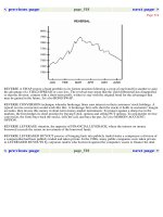
The fastest growing of these sectors is expected to be that for fresh and waste-
water treatment (the third largest sector), followed quite closely by the fi ne chemi-
cals and pharmaceuticals groups.
The separations business is becoming increasingly more technical, with more
stringent demands being continuously placed upon its products; in parallel with
1A FILTRATION AND SEPARATION
SECTION 1 BASIC PRINCIPLES
6
this, there is the obvious need for equipment suppliers to ensure that they have on
hand the highly knowledgeable engineers able to analyse and solve the consequent
problems.
The environment
At the time of writing, there is much concern being expressed about the global
environment and human infl uences upon it. Whether it is to do with climate change
and its probable human cause; continued starvation in large regions of an otherwise
rich world; or the conversion of a runaway consumption to a sustainable expansion,
large areas of the world are beginning to take note of changes in their environment,
and of the need to make parallel changes to the way in which life is conducted; in
particular, in energy consumption and fresh water provision.
The general importance of environmental protection justifi es mention of the topic
here – because fi ltration has a major role to play in many of the schemes trying
to achieve this protection. Environmental protection legislation has been in place
in the US and Europe for several decades now, but the benefi cial effects are only
just beginning to appear. Similar processes exist in other developed regions, but the
developing countries have hard decisions to take over whether to let expansion run
loose, to satisfy their people ’ s natural wish for higher standards of living, or to rein
it in, to give sustainability a chance.
The market forces exerted by the imposition of environmental legislation are
an important driver for the fi ltration market. The legislation calls for waste mini-
mization and for the treatment of unavoidable waste streams to continually higher
standards, both of which are well met by available and developing types of fi ltra-
tion equipment.
The separations industry itself can make a useful contribution to energy conser-
vation: all fi lters need some kind of driving force, especially in the higher pressure
membrane systems, and the design of fi lter systems to minimize their energy demands
is an important feature of the development of such systems.
Table 1.2 Sectoral market shares, 2007
End-use sector Market share (%)
Domestic, commercial and institutional 17.9
Transport equipment and systems 15.9
Fresh and wastewater treatment 10.3
Bulk chemicals 9.9
Food and beverage production 7.5
Fine chemical, pharmaceuticals and biochemicals 6.5
Power generation 6.3
Pulp and paper 5.1
Medical and health 4.8
Electrical and electronic materials and equipment 3.5
7
1B. CONTAMINANTS
Contaminants, i.e. minor impurities, are normally present in all fl uids, natural
or processed. Where the level of contamination in the fl uid is signifi cant, i.e. too
great for that fl uid to be consumed, or used for its proper purpose, or to be subse-
quently processed, then it becomes necessary (or in some cases legally obligatory)
to remove these impurities from the carrying fl uid, so as to reduce contamination to
or below acceptable levels.
These contaminants may be rigid or deformable solids, when they can be sep-
arated by a fi lter, or perhaps by a sedimentation process. Distinct liquid droplet
contaminants can also be removed in this way, using fi lter-like separators or sedi-
mentation. As indicated in Section 1A, where these contaminants are completely
mixed in the carrying fl uid (gas dispersed in a gas, liquid dissolved in another
liquid), then fi ltration or sedimentation are not suitable for their separation, and
phase change processes such as adsorption (e.g. with activated carbon, or perhaps
molecu lar sieves) must be used. The middle ground is occupied by some solid/liq-
uid or liquid/liquid solutions whose value is such as to justify purifying by means
of a membrane separation process.
The kind of situation being discussed here involves the presence in a fl uid of
some material, solid or liquid, that would be harmful to the consumer or other user
of that fl uid if it remains in that contaminated state. Thus a homogeneous suspen-
sion may carry rogue particles of a size much larger than that in the emulsion –
these can usually be removed quite easily by a scalping strainer. The coolant used
to lubricate and cool the cutting zone of a machine tool is a quite complex mix of
liquids, which is too expensive to throw away. After use it will normally be con-
taminated with the metal particles (swarf) removed from the item being machined,
so that before being recycled it must be freed of such contamination, in a fi lter, or
settling tank or centrifuge. The air in the modern city street is quite highly polluted
with diesel fumes among other things, and many people are now wearing personal
respirator masks to protect themselves against these impurities in the air that they
breathe. Surface water abstracted for drinking water production is frequently col-
oured to an unacceptable level by small quantities of colloidal solids, which may
require ultrafi ltration for their removal.
As can be seen from Figure 1.1 , the kinds of impurity carried in the atmospheric
air vary widely in size, with the greater proportion being invisible to the naked eye
(the limit of human vision being about 20 m). Such small particles, either in the
air or settled out into a liquid stream, are perfectly capable of sticking between
adjacent machinery surfaces and causing wear, or of collecting together to block a
liquid passage and so interfere with fl ow.
The separation of such contaminants from working or process fl uids is very
largely a task for fi ltration, in ways to be described later in this book. The only sig-
nifi cant decontamination process not using fi lters is the large volume process of set-
tlement of fresh or wastewater. Purifying processes on gas or liquid streams are often
required to treat such large volumes of fl uid. It obviously pays, therefore, to treat no
more than is absolutely necessary – the personal gas mask, for example, rather than
1B CONTAMINANTS
0.001
2 4 68 2 4 68 2 4 68 2 4 68 2 4 68 2 4 68 2 4 68
10,00010001001010.10.01
m
Diameter of particles and aerosols
Resin dust
Oil aerosol
Tobacco smoke
Metallurgical dust, fumes
Ammonium chloride
fumes
Concentrated
sulphuric fumes
Fertilizer, ground limestone
Fly ash
Coal dust
Cement dust
Coastal sand
Powdered coal
Flotation ores
Sulphur
fumes
Soot
Paint pigments
Zinc oxide fumes
Colloidal
silicon dioxide
Insecticide powder
Ground talc
Powdered milk
Alkali fume
Plant spores
Pollen
Flour
Atmospheric dust
Sea salt crystals
Atomizer droplets
Hydraulic jet droplets
Pneumatic
jet droplets
Human hair
Lung-damaging dust
Combustion
nuclei
Diameter, red blood corpuscles (warmed) 7.5 microns Ϯ 0.3 micron
Bacteria
Viruses
Figure 1.1 Impurities in air
9
all of the ambient air. Another approach to the treatment of large fl ows for contami-
nant removal is by taking off a sidestream and cleaning this completely, before mix-
ing it back into the main fl ow. With the correct ratio of sidestream to main fl ow, the
fi nal composition can be made acceptable.
It must be remembered that protection against contamination can often be a two-
way process. Thus, a working space may need protection from the contaminants
in ambient air by means of the provision of a controlled atmosphere. However, its
working materials may be suffi ciently toxic that the external environment may need
protection against unintentional emissions from inside the space, which means that
all vents from the working space, of whatever size, will need to be provided with
adequate fi lters or adsorbers.
Particle settlement
The critical factor in the creation and maintenance of dust-laden air or particle con-
taminated water is the nature of the particle, in terms of its size and its relative den-
sity. This is because of the development of a constant, terminal velocity by a particle
falling freely through a fl uid, whose value, as demonstrated by Stokes ’ law, is:
●
directly proportional to the square of the particle diameter
●
directly proportional to the difference between particle and fl uid densities
●
indirectly proportional to fl uid viscosity.
This relationship is strictly true only for spherical particles falling while isolated
from one another by some distance. Non-spherical particles are accounted for by
the use of an effective diameter (often determined by the reverse process of meas-
uring a terminal velocity and calculating back to the diameter). Stokes ’ law holds
well enough in the case of fl uids with a low solids concentration such as concerns a
study of contaminant removal.
If the particle size is small enough so that the terminal velocity is very low, or if
there are random movements in the fl uid at velocities in excess of this terminal fi gure,
then the particle effectively does not settle out, and a stable suspension results – which
may then need decontaminating. The settling velocity in air of a spherical particle,
whose specifi c gravity is 1, is given by:
18 10
52
. ϫϫ
Ϫ
d metres per minute
where d is the particle diameter, expressed in m. An array of values for terminal
settling velocities in air for a spherical particle with sg ϭ 1 is given in Table 1.3 .
Airborne contaminants
As shown in Figure 1.1 , airborne particles may range in size from 1 nm (0.001 m)
up to 1 mm or more. The larger particles, such as might come from heavy foundry
1B CONTAMINANTS
SECTION 1 BASIC PRINCIPLES
10
dust or ground limestone, would need updrafts of the order of 4 or 5 m/s to main-
tain them in suspension. For the very smallest, however, the settling velocities are
so low as for them to remain in suspension all the time – with the Brownian motion
of the molecules of the fl uid ensuring that they do so remain.
Particles in air suspension will range downwards from 100 m. Down to 20 m
they will be visible to the naked eye, while on down to 0.1–0.2 m they can be
observed with a conventional microscope. The major problem particles that are
viruses are smaller than this, and so that much more diffi cult to remove.
Typically, some 90% by weight of all airborne particulate impurities range from 0.1
to 10 μm in size, although this range and the actual concentration of solids will vary
markedly, dependent upon the immediately local environment and wind activity –
a desert sandstorm is far worse than any industrial activity.
If the air is, indeed, in motion, then quite large particles will be held in suspen-
sion, particularly if the fl ow is turbulent. Thus 10 m particles will be held up by
quite gentle air movements, while velocities of 0.3 m/s in a vertical direction, a
quite common fl ue gas regime, will keep 100 m particles suspended.
A somewhat different picture of contaminant size ranges is given in Figure 1.2
which also shows the capture ranges for several different types of separation
equipment.
Table 1.3 Approximate settling velocities in still air
(normally spherical particles of sgϭ1)
Particle size m Settling velocity
m/min ft/min
1000 245 800
600 183 600
500 150 500
400 137 450
300 122 400
200 75 250
100 18 60
90 14.5 48
80 11.5 38
70 9.0 29
60 6.5 21
50 4.5 15
40 3.0 9.5
30 1.6 5.35
20 0.7 2.33
10 0.2 0.60
5 0.045 0.15
1 0.0018 0.006
0.1 0.000018 0.00006
Active carbon
Range of HEPA filters
Paper and fabric filters
Range of membrane filters
Cyclone separators
Range of wet scrubbers
Bacteria
Spores
Pollen
Refractory dusts
Blast furnace dust
Aerosols
Pigments
Viruses
Machining dust
Sieves
Venturi scrubbers
Range of electrostatic precipitators
Determinable by light
scattering methods
Visible with
electron microscope
Visible with
human eye
Zinc oxide dust
Visible with microscope
0.001
0.005
0.01
0.05
0.1
Particle size m
0.5
1
2
3
4
5
10
20
30
40
50
100
Range of fabric dust collectors
Figure 1.2 Contaminant sizes and separators
SECTION 1 BASIC PRINCIPLES
12
Effect on humans
The average person breathes in about 12.5 m
3
or 16 kg of air each day. This is nor-
mal atmospheric air, which is far from clean. The breathing of contaminated air,
which may well contain particularly aggressive substances, is a frequent cause of
ill health, contributing to the common cold and infl uenza, emphysema, headaches,
eye irritation, coughing, dizziness, and the build-up of toxins in the bloodstream.
Impurities enter the body through the mouth and nose, and gradually becoming
deposited on the bronchial mucous membrane. At the initial stage of deposition,
the bronchial membrane itself is able to provide protective counteractions in the
form of sputum and coughing. This physical adjustment becomes impossible as a
result of repeated inhalation of contaminants and their inevitable deposits over an
extended period. As a consequence, the functions of the bronchi become abnor-
mal. In the lungs, congestion of the alveoli and irreversible fi brinous changes occur,
leading perhaps to pulmonary emphysema. Functional deterioration of the lungs
will affect the heart adversely, leading to heart disease.
This somewhat over-dramatic picture nevertheless highlights the need for clean
air for all human activity. Legislation such as the Health and Safety at Work Act is
taking care of the industrial environment, but only slow progress is being made to
protect the general ambient air. Steps towards alleviation of diesel engine pollution
are certainly in the right direction.
Effect on machines
Most engines take in air at a considerable rate: the factor of interest here is the
weight of solids that could be taken to the engine. The average automobile engine
inducts something like 9 or 10 m
3
of air for each litre of petrol burnt in its cylinders,
which corresponds to an annual intake of between 30,000 and 60,000 m
3
of air per
year. The solid particle content of this air is likely to be 0.3 to 0.6 kg, which, in the
absence of good fi ltration, would all deposit in the engine where its abrasive nature
would soon do serious damage. These fi gures correspond to a dust concentration
in the air of 10 mg/m
3
, and much worse conditions are readily identifi ed: a mineral
processor ’ s rock crusher could be working in a dust concentration up to 20 times
that fi gure. From another perspective, a land-based gas turbine could easily be tak-
ing in tens of thousands times the air volumes of an automobile.
Inducted solids will tend to accumulate as deposits on pistons, cylinder heads,
valves and other internal components, with the strong possibility of their being
bonded in place by the oil fi lm normally on these surfaces. The oil fi lm will thus
accumulate an abrasive content. Meanwhile, the dust still in the air will be washed
out by the oil mist, to collect in the lubricant and then be circulated through the
machine with dire consequences. In the drier interior of a gas turbine, the sus-
pended solids will quickly wear away the turbine blades.
Clearly such dust intake levels cannot be tolerated, and fi ltration systems must
be installed to remove the dust. Fitting a fi lter involves a compromise; fi rstly as to
its cut point, and secondly as to its energy needs. The fi ner the fi lter, the more dust