Design of machinery mechanisms and machines 2nd ed
Bạn đang xem bản rút gọn của tài liệu. Xem và tải ngay bản đầy đủ của tài liệu tại đây (40.45 MB, 924 trang )
DESIGN OF MACHINERY
AN INTRODUCTION TO THE SYNTHESIS AND
ANALYSIS OF MECHANISMS
AND MACHINES
Second Edition
McGraw-Hili Series in Mechanical Engineering
Jack P. Holman, Southern Methodist University
John R. Lloyd, Michigan State University
Consulting Editors
Anderson: Modern Compressible Flow: With Historical Perspective
Arora: Introduction to Optimum Design
Anderson: Computational Fluid Dynamics: The Basics with Applications
BormanlRagland: Combustion Engineering
Burton: Introduction to Dynamic Systems Analysis
Culp: Principles of Energy Conversion
Dieter: Engineering Design: A Materials and Processing Approach
Doebelin: Engineering Experimentation: Planning. £-cecution. Reporting
Dreils: Linear Controls Systems Engineering
Edwards and McKee: Fundamentals of Mechanical Component Design
Gebhart: Heat Conduction and Mass Diffusion
Gibson: Principles of Composite Material Mechanics
Hamrock: Fundamentals of Fluid Film LubricaIion
Heywood: Internal Combustion Engine Fundamenrals
Hinze: Turbulence
Holman: Experimental Methods for Engineers
Howell and Buckius: Fundamenrals ofEngiN!ering Thermodynamics
Jaluria: Design and Optimi::.ation ofTheTmill Systems
Juvinall: Engineering Considerations of Stress, Strain. and Strength
Kays and Crawford: Com'ectiw Heal and Jlass Transfer
Kelly: Fundamentals of Mechanical \'ibrarions
Kimbrell: Kinematics Analysis and Synthesis
Kreider and Rabl: Heating and Cooling of Buildings
Martin: Kinematics and Dynamics ofJlachines
Mattingly: Elements of Gas TurbiN! Propulsion
Modest: Radiati\'e Heat Transfer
Norton: Design of Machinery:
.411
Introduction to the Synthesis and Analysis of
Mechanisms and MachiN!s
Oosthuizien and CarscaIIeo: Compressible Fluid Flow
Phelan: Fundamentals of Mechanical Design
Reddy: An Introduction to the Finite Elemen: Method
Rosenberg and
Kamopp:
Introduction to Physical Systems Dynamics
Schlichting: Boundary-Layer Theory
Shames: Mechanics of Fluids
Shigley: Kinematic Analysis of Mechanisms
Shigley and Mischke: Mechanical Engineering Design
Shigley and Vicker: Theory of Machines and Mechanisms
Stimer: Design with Microprocessors for Mechanical Engineers
Stoeker and Jones: Refrigeration and Air Conditioning
Turns: An Introduction to Combustion: Concepts and Applications
Ullman: The Mechanical Design Process
Wark: Advanced Thermodynamics for Engineers
White: Viscous Flow
Zeid: CAD/CAM Theory and Practice
Mechanisms and Machines
Copyright © 1999 by McGraw-Hill Inc. All rights reserved. Previous edition © 1992. Printed in
the United States of America. Except as permitted under the United States Copyright Act of 1976,
no part of this publication may be reproduced or distributed in any form or by any means, or stored
in a database or retrieval system, without the prior written permission of the publisher.
This book is printed on acid-free paper.
I 2 3 4 5 6 7 8 9 0 QPF/QPF I 0 9 8
ISBN 0-07-048395-7
ISBN 0-07-913272-3 (set)
ISBN 0-04-847978-9 (CD-ROM)
Vice president and editorial director: Kevin T. Kane
Publisher: 1bomas Casson
Senior sponsoring editor: Debra Riegert
Developmental editor: Holly Stark
Marketing manager: John T. Wannemacher
Project manager: Christina Thomton- Villagomez
Production supervisor: Michael R. McCormick
Supplement Coordinator: Marc Mattson
Cover Design: Gino Cieslik
Book design: Wanda Siedlecka
Printer: Quebecor Printing Book Group/Fairfield
Cover photo: Viper cutaway courtesy of the Chrysler Corporation, Auburn Hills, MI.
All text, drawings. and equations in this book were prepared and typeset electronically, by the
author, on a Mocintosh® computer using Freehan~, MathType®, and Pagemaker® desktop
publishing software. The body text was set in Times Roman, and headings set in Avant Garde.
Printer's film color separations were made on a laser typesetter directly from the author's disks.
All clip art illustrations are courtesy of Dubl-Click Software Inc., 22521 Styles St., Woodland
Hills CA 91367. reprinted from their Industrial Revolution and Old Earth Almanac series with
their permission (and with the author's thanks).
Library of Congress Cataloging-in-Publication Data
Norton, Robert L.
Design of machinery: an introduction to the synthesis and analysis of mechanisms
and machines / Robert L. Norton - 2nd ed.
p. cm. {McGraw-Hill series in mechanical engineering)
Includes bibliographical references and index.
ISBN 0-07-048395-7
1. Machinery-Design. 2. Machinery, Kinematics. 3. Machinery,
Dynamics of. I. Title. II. Series.
TJ230.N63 1999 91-7510
621.8'15-dc20
ABOUT THE AUTHOR
Robert L. Norton earned undergraduate degrees in both mechanical engineering and in-
dustrial technology at Northeastern University and an MS in engineering design at Tufts
University. He is a registered professional engineer in Massachusetts and New Hamp-
shire. He has extensive industrial experience in engineering design and manufacturing
and many years experience teaching mechanical engineering, engineering design, com-
puter science, and related subjects at Northeastern University, Tufts University, and
Worcester Polytechnic Institute. At Polaroid Corporation for ten years, he designed cam-
eras, related mechanisms, and high-speed automated machinery. He spent three years at
Jet Spray Cooler Inc., Waltham, Mass., designing food-handling machinery and prod-
ucts. For five years he helped develop artificial-heart and noninvasive assisted-circula-
tion (counterpulsation) devices at the Tufts New England Medical Center and Boston
City Hospital. Since leaving industry to join academia, he has continued as an indepen-
dent consultant on engineering projects ranging from disposable medical products to
high-speed production machinery. He holds 13 U.S. patents.
Norton has been on the faculty of Worcester Polytechnic Institute since 1981 and is
currently professor of mechanical engineering and head of the design group in that de-
partment. He teaches undergraduate and graduate courses in mechanical engineering
with emphasis on design, kinematics, and dynamics of machinery. He is the author of
numerous technical papers and journal articles covering kinematics, dynamics of machin-
ery, carn design and manufacturing, computers in education, and engineering education
and of the text Machine Design: An Integrated Approach. He is a Fellow of the Ameri-
can Society of Mechanical Engineers and a member of the Society of Automotive Engi-
neers. Rumors about the transplantation of a Pentium microprocessor into his brain are
decidedly untrue (though he could use some additional RAM). As for the unobtainium*
ring, well, that's another story.
* See Index.
Thisbook isdedicated to the memory of my father,
Harry J. Norton, Sr.
who sparked a young boy's interest in engineering;
to the memory of my mother,
Kathryn W Norton
who made it all possible;
to my wife,
Nancy Norton
who provides unflagging patience and supp~rt;
and to my children,
Robert, Mary, and Thomas,
who make it all worthwhile.
CONTENTS
Preface to the Second Edition XVII
Preface to the First Edition XIX
PART
I
KINEMATICS OF MECHANISMS
1
Chapter 1
Introduction 3
1.0
Purpose 3
1.1
Kinematics and Kinetics 3
1.2
Mechanisms and Machines 4
1.3
A Brief History of Kinematics 5
1.4
Applications of Kinematics 6
1.5
The Design Process , 7
Design, Invention, Creativity
7
Identification
of
Need
8
Background Research ··········· 9
Goal Statement
9
Performance Specifications
9
Ideation and Invention
70
Analysis
77
Selection
72
Detailed Design ·········
73
Prototyping and Testing
73
Production
73
1.6
Other Approaches to Design " " " 14
Axiomatic Design ····
75
1.7
Multiple Solutions , 15
1.8
Human Factors Engineering " " " 15
1.9
The Engineering Report " 16
1.10
Units " 16
1.11
What's to Come " 18
1.12
References , 19
1.13
Bibliography " , 20
Chapter 2
Kinematics Fundamentals 22
2.0
Introduction , " " 22
2.1
Degrees of Freedom 22
2.2
Types of Motion " 23
2.3
Links, Joints, and Kinematic Chains 24
2.4
Determining Degree of Freedom " 28
Degree
of
Freedom in Planar Mechanisms
29
Degree
of
Freedom in Spatial Mechanisms
32
2.5
Mechanisms and Structures 32
2.6
Number Synthesis " " 33
2.7
Paradoxes 37
2.8
Isomers 38
2.9
Linkage Transformation 40
2.10
Intermittent Motion " 42
2.11
Inversion 44
2.12
The Grashof Condition 46
Classification of the Fourbar Linkage 49
2.13
Linkages of More Than Four Bars 52
Geared Fivebar Linkages 52
Sixbar Linkages 53
Grashof-type Rotatability Criteria for Higher-order Linkages 53
2.14
Springs as Links 54
2.15
Practical Considerations 55
Pin Joints versusSlidersand Half Joints 55
Cantilever versusStraddle Mount 57
Short Links
58
Bearing Ratio 58
Linkages versus
Cans
59
2.16
Motor and Drives 60
Electric Motexs 60
Air and HyaotAc Motexs 65
Air and Hyc:kotAc CyiIders 65
Solenoids 66
2.17
References 66
2.18
Problems 67
Chapter 3 Graphical Linkage Synthesis 76
3.0 Introduction 76
3.1 Synthesis 76
3.2 Function. Path. and Motion Generation 78
3.3 limiting Conditions ,80
3.4 Dimensional Synthesis , , , 82
Two-Posiffon Synthesis 83
TPY~n Synthesis with Specified Moving Pivots 89
1hree-Position Synthesis with Alternate Moving Pivots 90
TPYee-PositionSynthesis with Specified Fixed Pivots 93
Position Synthesis for More Than Three Positions 97
3.5 Quick-Return Mechanisms , ,97
Fou'bar Quick-Return 98
SbcbarQuick-Return 700
3.6 Coupler Curves " , 103
3.7
Cognates " " ", " " " " 112
Parallel Motion 777
Geared Rvebar Cognates of the Fourbar 779
3.8 Straight-Line Mechanisms ., , ", " " 120
Designing Optimum Straight-Line Fourbar Linkages 722
3.9 Dwell Mechanisms , , , , " 125
Single-Dwell Linkages 726
Double-Dwell Linkages 728
3.10
References , , , " 130
3.11
Bibliography , , , ", , 131
3.12
Problems " , 132
3.13
Projects , 140
Chapter 4
PositionAnalysis 144
4.0
Introduction , , , , 144
4.1
Coordinate Systems , , 146
4.2
Position and Displacement 147
Position 747
Displacement 747
4.3
Translation, Rotation, and Complex Motion 149
Translation
749
Rotation 749
Complex Motion
749
Theorems
750
4.4
Graphical Position Analysis of Linkages 151
4.5
Algebraic Position Analysis of Linkages 152
Vector Loop Representation of Linkages
753
Complex Numbers
as
Vectors
754
The Vector Loop Equation for
a
Fourbar Linkage
756
4.6
The Fourbar Slider-Crank Position Solution 159
4.7
An Inverted Slider-Crank Position Solution 161
4.8
Linkages of More Than Four Bars 164
The Geared Fivebar Linkage
764
Sixbar Linkages 767
4.9
Position of Any Point on a Linkage 168
4.10
Transmission Angles 169
Extreme Values of the TransmissionAngle
769
4.11
Toggle Positions 171
4.12
Circuits and Branches in Linkages 173
4.13
Newton-Raphson Solution Method 174
One-Dimensional Root-Finding (Newton's Method) 774
Multidimensional Root-Finding (Newton-Raphson Method)
776
Newton-Raphson Solution for the Fourbar Linkage
777
Equation Solvers
778
4.14
References 178
4.15
Problems 178
Chapter 5
Analytical Linkage Synthesis 188
5.0
Introduction 188
5.1
Types of Kinematic Synthesis 188
5.2
Precision Points 189
5.3
Two-Position Motion Generation by Analytical Synthesis 189
5.4
Comparison of Analytical and Graphical Two-Position Synthesis 196
5.5
Simultaneous Equation Solution 199
5.6
Three-Position Motion Generation by Analytical Synthesis 201
5.7
Comparison of Analytical and Graphical Three-Position Synthesis 206
5.8
Synthesis for a Specified Fixed Pivot Location 211
5.9
Center-Point and Circle-Point Circles 217
5.10
Four- and Five-Position Analytical Synthesis 219
5.11
Analytical Synthesis of a Path Generator with Prescribed Timing 220
5.12
Analytical Synthesis of a Fourbar Function Generator 220
5.13
Other Linkage Synthesis Methods 224
Precision Point Methods
226
CouplerCuNe Equation Methods 227
Optimization Methods 227
5.14
References 230
5.15
Problems , 232
Chapter 6
Velocity Analysis 241
6.0
Introduction , 241
6.1
Definition of Velocity , 241
6.2
Graphical Velocity Analysis 244
6.3 Instant Centers of Velocity 249
6.4 Velocity Analysis with Instant Centers 256
Angular Velocity Raffo 257
Mechanical Advantage 259
Using Instant Centers in Unkage Design 267
6.5
Centrodes 263
A 'UnkJess-Unkage 266
Cusps 267
6.6
Velocity of Slip 267
6.7
Analytical Solutions for Velocity Analysis 271
The FotIbar Pin-Jointed Unkage 277
The FotIbar Slider-Crank 274
The FotIbar Inverted Slider-Crank 276
6.8
Velocity Analysis of the Geared Fivebar Linkage 278
6.9
Velocity of Any Point on a Linkage 279
6.10
References 280
6.11
Problems
281
Chapter 7
Acceleration Analysis 300
7.0
Introduction 300
7.1 Definition of Acceleration 300
7.2
Graphical Acceleration Analysis 303
7.3
Analytical Solutions for Acceleration Analysis 308
The Fourbar Pin-Jointed Linkage 308
The Fourbar Slider-Crank 377
CorioIis Acceleration '" 3 73
The Fourbar Inverted Slider-Crank 375
7.4 Acceleration Analysis of the Geared Fivebar Linkage 319
7.5
Acceleration of any Point on a Linkage 320
7.6
Human Tolerance of Acceleration 322
7.7
Jerk 324
7.8
Linkages of N Bars 327
7.9
References 327
7.10
Problems 327
Chapter 8
Cam Design 345
8.0
Introduction 345
8.1 Cam Terminology 346
Type of Follower Motion 347
Type of Joint Closure 348
Type of Follower 348
Type of Cam 348
Type of Motion Constraints 357
Type of Motion Program 357
8.2
S
V A
J
Diagrams 352
8.3 Double-Dwell Cam Design-Choosing
S
V A
J
Functions 353
TheFundamental LawofCamDesign 356
Simple Harmonic Motion (SHM) 357
Cycloidal Displacement 359
Combined Functions 362
8.4 Single-Dwell Cam Design-Choosing
S
V A
J
Functions 374
8.5 Polynomial Functions 378
Double-Dwell Applications of Polynomials 378
Single-Dwell Applications of Polynomials 382
8.6 Critical Path Motion (CPM) 385
Polynomials Used for Critical Path Motion 386
Half-Period Harmonic Family Functions 393
8.7 Sizing the Com-Pressure Angle and Radius of Curvature 396
PressureAngle-Roller Followers 397
Choosing
a
Prime Circle Radius 400
Overturning Moment-Flat-Faced Follower 402
Radius of Curvature-Roller Follower 403
Radius of Curvature-Flat-Faced Follower 407
8.8
Com Manufacturing Considerations 412
Geometric Generation 413
Manual or NC Machining to Cam Coordinates (Plunge-Cutting) 413
Continuous Numerical Control with Linear Interpolation 414
Continuous Numerical Control with Circular Interpolation 416
Analog Duplication 416
Actual Cam Performance Compared to Theoretical Performance. 418
8.9 Practical Design Considerations 421
Translating or Oscillating Follower? 421
Force- or Form-Closed? , 422
Radial or Axial Cam? 422
Roller or Flat-Faced Follower? 423
ToDwell or Not to Dwell? 423
ToGrind or Not to Grind? 424
ToLubricate or Not to Lubricate? 424
8.10 References 424
8.11
Problems , 425
8.12
Projects 429
Chapter 9
Gear Trains 432
9.0 Introduction 432
9.1 Rolling Cylinders 433
9.2 The Fundamental Law of Gearing 434
TheInvolute Tooth Form 435
PressureAngle 437
Changing Center Distance 438
Backlash 438
9.3 Gear Tooth Nomenclature 440
9.4 Interference and Undercutting 442
Unequal-Addendum Tooth Forms 444
9.5 Contact Ratio 444
9.6 Gear Types 447
Spur, Helical, and Herringbone Gears 447
Worms and Worm Gears 448
Rack and Pinion 448
Bevel and Hypoid Gears 449
Noncircular Gears 450
Belt and Chain Drives 450
9.7 Simple Gear Trains 452
9.8 Compound Gear Trains ., 453
Design of Compound Trains 454
Design of Reverted Compound Trains 456
An Algorithm for the Design of Compound Gear Trains 458
9.9
Epicyclic or Planetary Gear Trains 462
The Tabular Method 464
The Formula Method , 469
9.10
Efficiency of Gear Trains 470
Com Dynamics 685
15.0 Introduction 685
15.1 Dynamic Force Analysis of the Force-Closed Cam Follower 686
Undamped Response,
686
Damped Response 689
15.2 Resonance 696
15.3 Kinetostatic Force Analysis of the Force-Closed Cam-Follower 698
15.4
Kinetostatic Force Analysis of the Form-Closed Cam-Follower. 702
15.5
Camshaft Torque 706
15.6
Measuring Dynamic Forces and Accelerations 709
15.7 Practical Considerations 713
15.8 References 713
15.9 Bibliography 713
15.10 Problems 714
Chapter 16
Engineering Design 717
16.0
Introduction 717
16.1
A Design Case Study 718
16.2
Closure 723
16.3
References 723
Appendix A
Computer Programs 725
AO
Introduction 725
A1
General Information 727
A2
General Program Operation 727
A3
Program FOURBAR 735
A4
Program FIVEBAR 743
A5
Program SIXBAR 745
A6
Program SLIDER 749
A7
Program DVNACAM 751
A8
Program ENGINE 757
A9
Program MATRIX , 764
Appendix B
Material Properties 765
Appendix C
Geometric Properties 769
Appendix D
Spring Data 771
Appendix E
Atlas of Geared Fivebar Linkage Coupler Curves 775
Appendix F Answers to Selected Problems 781
Index , 795
CD-ROM Index 809
PREFACE
to the Second Edition
Why is it we never have time to do
it right the first time, but always
seem to have time to do it over?
ANONYMOUS
The second edition has been revised based on feedback from a large number of users of the
book.
In
general, the material in many chapters has been updated to reflect the latest research
findings in the literature. Over 250 problem sets have been added, more than doubling the
total number of problems. Some design projects have been added also. All the illustrations
have been redrawn, enhanced, and improved.
Coverage of the design process in Chapter 1has been expanded. The discussions of the
Grashof condition and rotatability criteria in Chapter 2 have been strengthened and that of
electric motors expanded. A section on the optimum design of approximate straight line link-
ages has been added to Chapter 3. A discussion of circuits and branches in linkages and a
section on the Newton-Raphson method of solution have been added to Chapter 4. A discus-
sion of other methods for analytical and computational solutions to the position synthesis
problem has been added to Chapter 5. This reflects the latest publications on this subject and
is accompanied by an extensive bibliography.
The chapters formerly devoted to explanations of the accompanying software (old Chap-
ters 8 and 16) have been eliminated. Instead, a new Appendix A has been added to describe
the programs FOURBAR,FIVEBAR,SrXBAR,SLIDER,DYNACAM,ENGINE,and MATRIXthat are
on the attached CD-ROM. These programs have been completely rewritten as Windows ap-
plications and are much improved. A student version of the simulation program Working
Model by Knowledge Revolution, compatible with both Macintosh and Windows computers,
is also included on CD-ROM along with 20 models of mechanisms from the book done in
that package. A user's manual for Working Model is also on the CD-ROM.
Chapter 8 on cam design (formerly 9) has been shortened without reducing the scope of its
coverage. Chapter 9 on gear trains (formerly 10)has been significantly expanded and enhanced,
especially in respect to the design of compound and epicyclic trains and their efficiency. Chapter
10on dynamics fundamentals has been augmented with material formerly in Chapter 17to give a
more coherent treatment of dynamic modeling. Chapter 12 on balancing (formerly 13)has been
expanded to include discussion of moment balancing of linkages.
The author would like to express his appreciation to all the users and reviewers who have
made suggestions for improvement and pointed out errors, especially those who responded to the
survey about the first edition. There are too many to list here, sorather than risk offense by omit-
ting anyone, let me simply extend my sincerest thanks to you all for your efforts.
'.1{p6ertL. 'J,{prton
:Mattapoisett
l
:Mass.
5tugust
l
1997
PREFACE
to the First Edition
When I hear, Iforget
When I see, I remember
When I do, I understand
ANCIENT CHINESE PROVERB
This text is intended for the kinematics and dynamics of machinery topics which are of-
ten given as a single course, or two-course sequence, in the junior year of most mechan-
ical engineering programs. The usual prerequisites are first courses in statics, dynamics
and calculus. Usually, the first semester, or portion, is devoted to kinematics, and the sec-
ond to dynamics of machinery. These courses are ideal vehicles for introducing the me-
chanical engineering student to the process of design, since mechanisms tend to be intu-
itive for the typical mechanical engineering student to visualize and create. While this
text attempts to be thorough and complete on the topics of analysis, it also emphasizes
the synthesis and design aspects of the subject to a greater degree than most texts in print
on these subjects. Also, it emphasizes the use of computer-aided engineering as an ap-
proach to the design and analysis of this class of problems by providing software that can
enhance student understanding. While the mathematical level of this text is aimed at sec-
ond- or third-year university students, it is presented de novo and should be understand-
able to the technical school student as well.
Part I of this text is suitable for a one-semester or one-term course in kinematics.
Part II is suitable for a one-semester or one-term course in dynamics of machinery. Alter-
natively, both topic areas can be covered in one semester with less emphasis on some of
the topics covered in the text.
The writing and style of presentation in the text is designed to be clear, informal, and
easy to read. Many example problems and solution techniques are presented and spelled
out in detail, both verbally and graphically. All the illustrations are done with computer-
drawing or drafting programs. Some scanned photographic images are also included.
The entire text, including equations and artwork, is printed directly from computer disk
by laser typesetting for maximum clarity and quality. Many suggested readings are pro-
vided in the bibliography. Short problems, and where appropriate, many longer, unstruc-
tured design project assignments are provided at the ends of chapters. These projects
provide an opportunity for the students to do and understand.
The author's approach to these courses and this text is based on over 35 years'
experience in mechanical engineering design, both in industry and as a consultant.
He has taught these subjects since 1967, both in evening school to practicing engi-
neers and in day school to younger students. His approach to the course has evolved
a great deal in that time, from a traditional approach, emphasizing graphical analysis of
many structured problems, through emphasis on algebraic methods as computers be-
came available, through requiring students to write their own computer programs, to
the current state described above.
The one constant throughout has been the attempt to convey the art of the design pro-
cess to the students in order to prepare them to cope with
real
engineering problems in
practice. Thus, the author has always promoted design within these courses. Only re-
cently, however, has technology provided a means to more effectively accomplish this
goal, in the form of the graphics microcomputer. This text attempts to be an improve-
ment over those currently available by providing up-to-date methods and techniques for
analysis and synthesis which take full advantage of the graphics microcomputer, and by
emphasizing design as well as analysis.
The text also provides a more complete, mod-
em, and thorough treatment of cam design than existing texts in print on the subject.
The author has written several interactive, student-friendly computer programs for
the design and analysis of mechanisms and machines. These programs are designed to
enhance the student's understanding of the basic concepts in these courses while simul-
taneously allowing more comprehensive and realistic problem and project assignments
to be done in the limited time available, than could ever be done with manual solution
techniques, whether graphical or algebraic. Unstructured, realistic design problems which
have many valid solutions are assigned. Synthesis and analysis are equally emphasized.
The analysis methods presented are up to date, using vector equations and matrix tech-
niques wherever applicable. Manual graphical analysis methods are de-emphasized. The
graphics output from the computer programs allows the student to see the results of vari-
ation of parameters rapidly and accurately and reinforces learning.
These computer programs are distributed, on CD-ROM, with this book which also
contains instructions for their use on any IBM compatible, Windows 3.1 or Windows 95/
NT capable computer. The earlier DOS versions of these programs are also included for
those without access to Windows. Programs SLIDER,FOURBAR,FIVEBARand SIXBARan-
alyze the kinematics of those types of linkages. Program FOURBARalso does a complete
dynamic analysis of the fourbar linkage in addition to its kinematics. Program DYNACAM
allows the design and dynamic analysis of cam-follower systems. Program ENGINEan-
alyzes the slider-crank linkage as used in the internal combustion engine and provides a
complete dynamic analysis of single and multicylinder engine configurations, allowing
the mechanical dynamic design of engines to be done. Program MATRIXis a general pur-
pose linear equation system solver. All these programs, except MATRIX,provide dynam-
ic, graphical animation of the designed devices. The reader is strongly urged to make use
of these programs in order to investigate the results of variation of parameters in these ki-
nematic devices. The programs are designed to enhance and augment the text rather than
be a substitute for it. The converse is also true. Many solutions to the book's examples
and to the problem sets are provided on the CD-ROM as files to be read into these pro-
grams. Many of these solutions can be animated on the computer screen for a better dem-
onstration of the concept than is possible on the printed page. The instructor and students
are both encouraged to take advantage of the computer programs provided. Instructions
for their use are in Appendix A.
The author's intention is that synthesis topics be introduced first to allow the
students to work on some simple design tasks early in the term while still mastering
the analysis topics. Though this is not the "traditional" approach to the teaching of
this material, the author believes that it is a superior method to that of initial concen-
tration on detailed analysis of mechanisms for which the student has no concept of or-
igin or purpose. Chapters 1 and 2 are introductory. Those instructors wishing to
teach analysis before synthesis can leave Chapters 3 and 5 on linkage synthesis for
later consumption. Chapters 4, 6, and 7 on position, velocity, and acceleration anal-
ysis are sequential and build upon each other. In fact, some of the problem sets are com-
mon among these three chapters so that students can use their position solutions to find
velocities and then later use both to find the accelerations in the same linkages.
Chapter 8 on cams is more extensive and complete than that of other kinematics texts
and takes a design approach. Chapter 9 on gear trains is introductory. The dynamic force
treatment in Part II uses matrix methods for the solution of the system simultaneous
equations. Graphical force analysis is not emphasized. Chapter 10 presents an intro-
duction to dynamic systems modelling. Chapter
11
deals with force analysis oflinkag-
es. Balancing of rotating machinery and linkages is covered in Chapter 12. Chapters 13
and 14 use the internal combustion engine as an example to pull together many dynamic
concepts in a design context. Chapter 15 presents an introduction to dynamic systems
modelling and uses the cam-follower system as the example. Chapters 3, 8, 11, 13,
and 14 provide open ended project problems as well as structured problem sets. The
assignment and execution of unstructured project problems can greatly enhance the
student's understanding of the concepts as described by the proverb in the epigraph
to this preface.
ACKNOWLEDGMENTS
The sources of photographs and other nonoriginal art
used in the text are acknowledged in the captions and opposite the title page, but the
author would also like to express his thanks for the cooperation of all those individ-
uals and companies who generously made these items available. The author would
also like to thank those who have reviewed various sections of the first edition of the
text and who made many useful suggestions for improvement. Mr. John Titus of the
University of Minnesota reviewed Chapter 5 on analytical synthesis and Mr. Dennis
Klipp of Klipp Engineering, Waterville, Maine, reviewed Chapter 8 on cam design.
Professor William J. Crochetiere and Mr. Homer Eckhardt of Tufts University, Med-
ford, Mass., reviewed Chapter 15. Mr. Eckhardt and Professor Crochetiere of Tufts,
and Professor Charles Warren of the University of Alabama taught from and re-
viewed Part I. Professor Holly K. Ault of Worcester Polytechnic Institute thorough-
ly reviewed the entire text while teaching from the pre-publication, class-test ver-
sions of the complete book. Professor Michael Keefe of the University of Delaware
provided many helpful comments. Sincere thanks also go to the large number of un-
dergraduate students and graduate teaching assistants who caught many typos and errors
in the text and in the programs while using the pre-publication versions. Since the book's
first printing, Profs. D. Cronin, K. Gupta, P.Jensen, and Mr. R. Jantz have written to point
out errors or make suggestions which I have incorporated and for which I thank them.
The author takes full responsibility for any errors that may remain and invites from all
readers their criticisms, suggestions for improvement, and identification of errors in the
text or programs, so that both can be improved in future versions.
'R.P6ertL. :lI{prton
:Mattapoisett/ :Mass.
5lugust/ 1991
Take
to Kinematics. It will repay you. It is
more fecund than geometry;
it adds afourth dimension to space.
CHEBYSCHEV TO SYLVESTER, 1873
1.0 PURPOSE
In this text we will explore the topics of kinematics and dynamics of machinery in re-
spect to the synthesis of mechanisms in order to accomplish desired motions or tasks,
and also the analysis of mechanisms in order to determine their rigid-body dynamic
behavior. These topics are fundamental to the broader subject of machine design. On
the premise that we cannot analyze anything until it has been synthesized into existence,
we will first explore the topic of synthesis of mechanisms. Then we will investigate
techniques of analysis of mechanisms. All this will be directed toward developing your
ability to design viable mechanism solutions to real, unstructured engineering problems
by using a design process. We will begin with careful definitions of the terms used in
these topics.
1.1 KINEMATICS AND KINETICS
KINEMATICS
The study of motion without regard toforces.
KINETIcs
The study offorces on systems in motion.
These two concepts are really not physically separable. We arbitrarily separate them for
instructional reasons in engineering education. It is also valid in engineering design
practice to first consider the desired kinematic motions and their consequences, and then
subsequently investigate the kinetic forces associated with those motions. The student
should realize that the division between kinematics and kinetics is quite arbitrary and
is done largely for convenience. One cannot design most dynamic mechanical systems
without taking both topics into thorough consideration. It is quite logical to consider
them in the order listed since, from Newton's second law, F
=
ma, one typically needs to
3
know the accelerations (a) in order to compute the dynamic forces (F) due to the mo-
tion of the system's mass (m). There are also many situations in which the applied forc-
es are known and the resultant accelerations are to be found.
One principal aim of kinematics is to create (design) the desired motions of the sub-
ject mechanical parts and then mathematically compute the positions, velocities, and ac-
celerations which those motions will create on the parts. Since, for most earthbound
mechanical systems, the mass remains essentially constant with time, defining the accel-
erations as a function of time then also defines the dynamic forces as a function of time.
Stresses, in turn, will be a function of both applied and inertial (ma) forces. Since engi-
neering design is charged with creating systems which will not fail during their expected
service life, the goal is to keep stresses within acceptable limits for the materials chosen
and the environmental conditions encountered. This obviously requires that all system
forces be defined and kept within desired limits. In machinery which moves (the only
interesting kind), the largest forces encountered are often those due to the dynamics of
the machine itself. These dynamic forces are proportional to acceleration, which brings
us back to kinematics, the foundation of mechanical design. Very basic and early deci-
sions in the design process involving kinematic principles can be crucial to the success
of any mechanical design. A design which has poor kinematics will prove troublesome
and perform badly.
1.2 MECHANISMS AND MACHINES
A mechanism is a device which transforms motion to some desirable pattern and typi-
cally develops very low forces and transmits little power. A machine typically contains
mechanisms which are designed to provide significant forces and transmit significant
powerJI] Some examples of common mechanisms are a pencil sharpener, a camera shut-
ter, an analog clock, a folding chair, an adjustable desk lamp, and an umbrella. Some
examples of machines which possess motions similar to the mechanisms listed above are
a food blender, a bank vault door, an automobile transmission, a bulldozer, a robot, and
an amusement park ride. There is no clear-cut dividing line between mechanisms and
machines. They differ in degree rather than in kind. If the forces or energy levels within
the device are significant, it is considered a machine; if not, it is considered a mechanism.
A useful working definition of a mechanism is A system of elements arranged to trans-
mit motion in a predetermined fashion. This can be converted to a definition of a ma-
chine by adding the words and energy after motion.
Mechanisms, if lightly loaded and run at slow speeds, can sometimes be treated
strictly as kinematic devices; that is, they can be analyzed kinematically without regard
to forces. Machines (and mechanisms running at higher speeds), on the other hand, must
first be treated as mechanisms, a kinematic analysis of their velocities and accelerations
must be done, and then they must be subsequently analyzed as dynamic systems in which
their static and dynamic forces due to those accelerations are analyzed using the princi-
ples of kinetics. Part I of this text deals with Kinematics of Mechanisms, and Part II
with Dynamics of Machinery. The techniques of mechanism synthesis presented in Part
I are applicable to the design of both mechanisms and machines, since in each case some
collection of moveable members must be created to provide and control the desired
motions and geometry.
1.3 A BRIEFHISTORY OF KINEMATICS
Machines and mechanisms have been devised by people since the dawn of history. The
ancient Egyptians devised primitive machines to accomplish the building of the pyra-
mids and other monuments. Though the wheel and pulley (on an axle) were not known
to the Old Kingdom Egyptians, they made use of the lever, the inclined plane (or wedge),
and probably the log roller. The origin of the wheel and axle is not definitively known.
Its first appearance seems to have been in Mesopotamia about 3000 to 4000 B.C.
A great deal of design effort was spent from early times on the problem of timekeep-
ing as more sophisticated clockworks were devised. Much early machine design was
directed toward military applications (catapults, wall scaling apparatus, etc.). The term
civil engineering was later coined to differentiate civilian from military applications of
technology. Mechanical engineering had its beginnings in machine design as the in-
ventions of the industrial revolution required more complicated and sophisticated solu-
tions to motion control problems. James Watt (1736-1819) probably deserves the title
of first kinematician for his synthesis of a straight-line linkage (see Figure 3-29a on p.
121) to guide the very long stroke pistons in the then new steam engines. Since the plan-
er was yet to be invented (in 1817), no means then existed to machine a long, straight
guide to serve as a crosshead in the steam engine. Watt was certainly the first on record
to recognize the value of the motions of the coupler link in the fourbar linkage. Oliver
Evans (1755-1819) an early American inventor, also designed a straight-line linkage for
a steam engine. Euler (1707-1783) was a contemporary of Watt, though they apparent-
ly never met. Euler presented an analytical treatment of mechanisms in his Mechanica
sive Motus Scienta Analytice Exposita (1736-1742), which included the concept that pla-
nar motion is composed of two independent components, namely, translation of a point
and rotation of the body about that point. Euler also suggested the separation of the prob-
lem of dynamic analysis into the "geometrical" and the "mechanical" in order to simpli-
fy the determination of the system's dynamics. Two of his contemporaries, d' Alembert
and Kant, also proposed similar ideas. This is the origin of our division of the topic into
kinematics and kinetics as described above.
In the early 1800s, L'Ecole Polytechnic in Paris, France, was the repository of engi-
neering expertise. Lagrange and Fourier were among its faculty. One of its founders
was Gaspard Monge (1746-1818), inventor of descriptive geometry (which incidental-
ly was kept as a military secret by the French government for 30 years because of its
value in planning fortifications). Monge created a course in elements of machines and
set about the task of classifying all mechanisms and machines known to mankind! His
colleague, Hachette, completed the work in 1806 and published it as what was probably
the first mechanism text in 1811. Andre Marie Ampere (1775-1836), also a professor
at L'Ecole Polytechnic, set about the formidable task of classifying "all human knowl-
edge." In his Essai sur la Philosophie des Sciences, he was the first to use the term "ein-
ematique," from the Greek word for motion,* to describe the study of motion without
regard to forces, and suggested that "this science ought to include all that can be said with
respect to motion in its different kinds, independently of the forces by which it is pro-
duced." His term was later anglicized to kinematics and germanized to kinematik.
Robert Willis (1800-1875) wrote the text Principles of Mechanism in 1841 while a
professor of natural philosophy at the University of Cambridge, England. He attempted
to systematize the task of mechanism synthesis. He counted five ways of obtaining rel-
*
Ampere is quoted as
writing "(The science of
mechanisms) must
therefore not define a
machine, as has usually
been done, as an instru-
ment by the help of which
the direction and intensity
of a given force can be
altered, but as an
instrument by the help of
which the direction and
velocity of a given motion
can be altered. To this
science
I
have given the
name Kinematics from
KtVIl<x-motion." in
Maunder, L. (1979).
"Theory and Practice."
Proc. 5th World Congo on
Theory of Mechanisms and
Machines, Montreal, p.
I.
ative motion between input and output links: rolling contact, sliding contact, linkages,
wrapping connectors (belts, chains), and tackle (rope or chain hoists). Franz Reuleaux
(1829-1905), published Theoretische Kinematik in 1875. Many of his ideas are still cur-
rent and useful. Alexander Kennedy (1847-1928) translated Reuleaux into English in
1876. This text became the foundation of modem kinematics and is still in print! (See
bibliography at end of chapter.) He provided us with the concept of a kinematic pair
(joint), whose shape and interaction define the type of motion transmitted between ele-
ments in the mechanism. Reuleaux defined six basic mechanical components: the link,
the wheel, the cam, the screw, the ratchet, and the belt. He also defined "higher" and
"lower" pairs, higher having line or point contact (as in a roller or ball bearing) and low-
er having surface contact (as in pin joints). Reuleaux is generally considered the father
of modem kinematics and is responsible for the symbolic notation of skeletal, generic
linkages used in all modem kinematics texts.
In this century, prior to World War II, most theoretical work in kinematics was done
in Europe, especially in Germany. Few research results were available in English. In
the United States, kinematics was largely ignored until the 1940s, when A. E. R. De-
Jonge wrote "What Is Wrong with 'Kinematics' and 'Mechanisms'?,"[2] which called
upon the U.S. mechanical engineering education establishment to pay attention to the Eu-
ropean accomplishments in this field. Since then, much new work has been done, espe-
cially in kinematic synthesis, by American and European engineers and researchers such
as J. Denavit, A. Erdman, F. Freudenstein, A. S. Hall, R. Hartenberg, R. Kaufman,
B. Roth, G. Sandor, andA. Soni, (all of the U.S.) and K. Hain (of Germany). Since the
fall of the "iron curtain" much original work done by Soviet Russian kinematicians has
become available in the United States, such as that by Artobolevsky.[3] Many U.S. re-
searchers have applied the computer to solve previously intractable problems, both of
analysis and synthesis, making practical use of many of the theories of their predeces-
sors.[4] This text will make much use of the availability of computers to allow more ef-
ficient analysis and synthesis of solutions to machine design problems. Several comput-
er programs are included with this book for your use.
1.4
APPLICATIONS OF KINEMATICS
One of the first tasks in solving any machine design problem is to determine the kine-
matic configuration(s) needed to provide the desired motions. Force and stress analyses
typically cannot be done until the kinematic issues have been resolved. This text address-
es the design of kinematic devices such as linkages, cams, and gears. Each of these terms
will be fully defined in succeeding chapters, but it may be useful to show some exam-
ples of kinematic applications in this introductory chapter. You probably have used many
of these systems without giving any thought to their kinematics.
Virtually any machine or device that moves contains one or more kinematic ele-
ments such as linkages, cams, gears, belts, chains. Your bicycle is a simple example of a
kinematic system that contains a chain drive to provide torque multiplication and sim-
ple cable-operated linkages for braking. An automobile contains many more examples
of kinematic devices. Its steering system, wheel suspensions, and piston-engine all con-
tain linkages; the engine's valves are opened by cams; and the transmission is full of
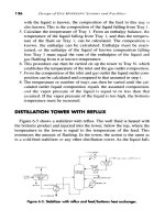
gears. Even the windshield wipers are linkage-driven. Figure l-la shows a spatial link-
age used to control the rear wheel movement of a modem automobile over bumps.
Construction equipment such as tractors, cranes, and backhoes all use linkages ex-
tensively in their design. Figure 1-1b shows a small backhoe that is a linkage driven by
hydraulic cylinders. Another application using linkages is thatof exercise equipment as
shown in Figure I-Ie. The examples in Figure 1-1 are all of consumer goods which you
may encounter in your daily travels. Many other kinematic examples occur in the realm
of producer goods-machines used to make the many consumer products that we use.
You are less likely to encounter these outside of a factory environment. Once you be-
come familiar with the terms and principles of kinematics, you will no longer be able to
look at any machine or product without seeing its kinematic aspects.
1.5 THEDESIGN PROCESS
Design, Invention, Creativity
These are all familiar terms but may mean different things to different people. These
terms can encompass a wide range of activities from styling the newest look in clothing,
to creating impressive architecture, to engineering a machine for the manufacture of fa-
cial tissues. Engineering design, which we are concerned with here, embodies all three
of these activities as well as many others. The word design is derived from the Latin
designare, which means "to designate, or mark out." Webster's gives several defini-
tions, the most applicable being "to outline, plot, or plan, as action or work to con-
ceive, invent- contrive." Engineering design has been defined as " the process ofap-
plying the various techniques and scientific principles for the purpose of defining a de-
vice, a process or a system in sufficient detail to permit its realization Design may
be simple or enormously complex, easy or difficult, mathematical or nonmathematical;
it may involve a trivial problem or one of great importance." Design is a universal con-
stituent of engineering practice. But the complexity of engineering subjects usually re-
DESIGN OF MACHINERY
CHAPTER 1
quires that the student be served with a collection of structured, set-piece problems
designed to elucidate a particular concept or concepts related to the particular topic.
These textbook problems typically take the form of "given A, B, C, and D, find E." Un-
fortunately, real-life engineering problems are almost never so structured. Real design
problems more often take the form of "What we need is aframus to stuff this widget into
that hole within the time allocated to the transfer of this other gizmo." The new engi-
neering graduate will search in vain among his or her textbooks for much guidance to
solve such a problem. This unstructured problem statement usually leads to what is
commonly called "blank paper syndrome." Engineers often find themselves staring at
a blank sheet of paper pondering how to begin solving such an ill-defined problem.
Much of engineering education deals with topics of analysis, which means to de-
compose, to take apart, to resolve into its constituent parts. This is quite necessary. The
engineer must know how to analyze systems of various types, mechanical, electrical,
thermal, or fluid. Analysis requires a thorough understanding of both the appropriate
mathematical techniques and the fundamental physics of the system's function. But,
before any system can be analyzed, it must exist, and a blank sheet of paper provides lit-
tle substance for analysis. Thus the first step in any engineering design exercise is that
of synthesis, which means putting together.
The design engineer, in practice, regardless of discipline, continuously faces the
challenge of structuring the unstructured problem. Inevitably, the problem as posed to
the engineer is ill-defined and incomplete. Before any attempt can be made to analyze
the situation he or she must first carefully define the problem, using an engineering ap-
proach, to ensure that any proposed solution will solve the right problem. Many exam-
ples exist of excellent engineering solutions which were ultimately rejected because they
solved the wrong problem, i.e., a different one than the client really had.
Much research has been devoted to the definition of various "design processes" in-
tended to provide means to structure the unstructured problem and lead to a viable solu-
tion. Some of these processes present dozens of steps, others only a few. The one pre-
sented in Table 1-1 contains 10 steps and has, in the author's experience, proven success-
ful in over 30 years of practice in engineering design.
ITERATION
Before discussing each of these steps in detail it is necessary to point
out that this is not a process in which one proceeds from step one through ten in a linear
fashion. Rather it is, by its nature, an iterative process in which progress is made halt-
ingly, two steps forward and one step back. It is inherently circular. To iterate means to
repeat, to return to a previous state. If, for example, your apparently great idea, upon
analysis, turns out to violate the second law of thermodynamics, you can return to the
ideation step and get a better idea! Or, if necessary, you can return to an earlier step in
the process, perhaps the background research, and learn more about the problem. With
the understanding that the actual execution of the process involves iteration, for simplic-
ity, we will now discuss each step in the order listed in Table 1-1.
Identification of Need
This first step is often done for you by someone, boss or client, saying "What we need is
" Typically this statement will be brief and lacking in detail. It will fall far short of
providing you with a structured problem statement. For example, the problem statement
might be "We need a better lawn mower."