Build Your Own Solar Panel
Bạn đang xem bản rút gọn của tài liệu. Xem và tải ngay bản đầy đủ của tài liệu tại đây (31 MB, 903 trang )
Copyright ©2007
Phillip Hurley and
Good Idea Creative Services
ALL RIGHTS RESERVED
i
Build Your Own Solar Panel
by Phillip Hurley
revised and expanded
copyright ©2000, 2006 Phillip Hurley
all rights reserved
illustrations and e-book design
copyright ©2000, 2006 Good Idea Creative Services
all rights reserved
ISBN-10: 0-9710125-2-0
ISBN-13: 978-0-9710125-2-3
Wheelock Mountain Publications
is an imprint of
Good Idea Creative Services
Wheelock VT
USA
Copyright ©2007
Phillip Hurley and
Good Idea Creative Services
ALL RIGHTS RESERVED
iii
View
If you wish to use “full screen view
”
, hit the keys “control-L” (Windows) or
“command-L” (Mac). To return to your normal desk-top view, hit the “esc” key.
If a watermark is visible when viewing the pages on screen, be sure that you
are viewing the e-book with Adobe Acrobat 6.0 or newer, and not a different
PDF reader such as Preview for Mac OSX.
Text links
Click on maroon colored text to go to a link within the e-book.
Click on
blue colored text to go to an external link on the internet. The link
will automatically open your browser. You must be connected to the internet to
view the externally linked pages.
Buttons
The TOC button will take you to the first page of the Table of Contents.
The left pointing triangle will take you to the previous page.
The right pointing triangle will take you to the next page.
How to Use this E-Book
Copyright ©2007
Phillip Hurley and
Good Idea Creative Services
ALL RIGHTS RESERVED
iv
Table of Contents
Click on the chapter head or subheading page number
to go to the section or chapter
Table of Contents continued
on the
next page
Notice of Rights ii
How to Use this E-Book iii
Introductio
n
Solar cells
Solar cell basics 3
Amorphous cells 4
Flexible solar cells 6
Crystalline solar cells 7
Monocrystalline and
polycrystalline cells
8
New cells vs. old-style cells 9
Solar cell output 10
Watt rating of solar cells 11
Testing solar cells 12
Match solar cell output 12
Tools for testing solar cells 13
Using a calibrated cell 15
Solar Panel
s
Solar panel output for
different applications
17
Solar panel ratings 18
Designer watts 19
Finding and choosing cells
for solar panels
20
Tab and bus ribbon 21
Panel frames 23
Thermal resistance 24
Moisture resistance 25
UV resistance 26
Glass in solar panels 26
Plexiglas in solar panels 27
Solar panel backing and sides 28
The benefits of long screws 28
Planning the panel wiring – series
and parallel connections
29
Voltage and distance to the battery 31
Panel arrays and connections 32
Panel size and shape 32
Copyright ©2007
Phillip Hurley and
Good Idea Creative Services
ALL RIGHTS RESERVED
v
Connecting solar cells
Choose and inspect the
cells carefully
33
Preparing the tab ribbon 34
Flux 35
Soldering 36
Soldering tips 37
Soldering technique 37
Types of solder 39
Building a solar panel
Materials and tools 41
Figuring panel output 42
Calculate the number of cells
you will need
42
Plan the panel layout 42
Over-all panel length 44
Over-all panel width 45
Bar stock length 46
Cut the tab ribbon 46
Prepare the tab ribbon 47
Tinning 47
Crimp the tab ribbon 48
Attach the tab ribbon to the cells 48
Pre-tabbed cells 50
Make a layout template 50
Solder the cells together 51
Prepare the panel structure 54
Attach the screen 55
Place the cells on the panel 55
Attach the tab ribbons
to the bus ribbons
56
Insulate the bus connectors 57
Junction box 57
Test the panel 58
Seal the panel 58
A small solar panel array project
Solar II project specifications 60
Panel layout and dimensions 61
Panel construction
Panel backing 64
Cutting the Plexiglas 68
Drilling the Plexiglas 69
Click on the chapter head or subheading page number
to go to the section or chapter
Table of Contents continued
on the
next page
Table of Contents
Copyright ©2007
Phillip Hurley and
Good Idea Creative Services
ALL RIGHTS RESERVED
vi
Drill Plexiglas, backing and
sidebars together
71
Output holes 71
Attach sidebars to backing 72
Attach screen to backing 73
Junction box 75
Tab and bus ribbon 79
Coating interior panel parts 80
Cell preparation 81
Tab ribbon length 82
Soldering tab ribbon to the cells 82
Cell layout template boards 83
String construction 84
Plexiglas cover 94
Panel clips 96
Purchasing and working
with solar cells
Off-spec or cosmetically
blemished solar cells
101
Repairing solar cells 102
Creating cell fingers 104
Using broken solar cells 107
Making tab and bus ribbon
Tinning the cut foil 113
Other options for connecting cells 115
Encapsulant
s
De-aerate the silicone 119
Cutting the silicone 121
Solar electric system
Charge controllers 126
Cables and connectors 127
Batteries 128
Mounting panels 129
Solar panel location 129
Orientation 130
Panel maintenance 130
Appendix
Tools and materials 131
Suppliers 137
Other titles of interest 139
Click on the chapter head or subheading page number
to go to the section or chapter
Table of Contents
Copyright ©2007
Phillip Hurley and
Good Idea Creative Services
ALL RIGHTS RESERVED
1
Introduction
Converting solar energy to electricity via photovoltaic cells is one of the most
exciting and practical scientific discoveries of the last several hundred years. The
use of solar power is far less damaging to the environment than burning fossil
fuels to generate power. In comparison to other renewable energy resources such
as hydro power, wind, and geothermal, solar has unmatched portability and thus
flexibility. The sun shines everywhere. These characteristics make solar power a
key energy source as we move away from our fossil fuel dependency, and toward
more sustainable and clean ways to meet our energy needs.
The sun is a powerful energy resource. Although very little of the billions of
megawatts per second generated by the sun reaches our tiny Earth, there is
more than enough to be unlimited in potential for terrestrial power production.
The sunlight that powers solar cells travels through space at 186,282 miles per
hour to reach the earth 8.4 minutes after leaving the surface of the sun. About
1,368 W/M
2
is released at the top of the earth’s atmosphere. Although the solar
energy that reaches the Earth’s surface is reduced due to water vapor, ozone
layer absorption and scattering by air molecules, there is still plenty of power for
us to collect. Harvesting photons for use in homes, factories, offices, vehicles
and personal electronics has become practical, and economical, and will con
-
tinue to increase in its importance in the energy supply equation.
Copyright ©2007
Phillip Hurley and
Good Idea Creative Services
ALL RIGHTS RESERVED
2
Introduction
In my opinion, the most exciting aspect of photovoltaic power generation is
that it creates opportunities for the individual power consumer to be involved in
the production of power. Even if it is only in a small way, you can have some con
-
trol of where your energy comes from.
Almost anyone can set up a solar panel and use the power
– independent of
the grid and other “powers that be.
” Batteries and supercapacitors for the elec-
tronic devices that we use on a daily basis can be recharged by this natural and
renewable energy resource. Doing so cuts down on pollution and makes life bet
-
ter for everyone. Practically every aspect of our lives will be touched in a positive
way by the increasing use of solar electric power.
Copyright ©2007
Phillip Hurley and
Good Idea Creative Services
ALL RIGHTS RESERVED
3
Solar Cells
Solar cell basics
A solar cell is a solid state semiconductor device that produces DC (direct
current) electricity when stimulated by photons. When the photons contact the
atomic structure of the cell, they dislodge electrons from the atoms. This leaves a
void which attracts other free available electrons. If a PN junction is fabricated in
the cell, the dislodged photons flow towards the P side of the junction. The result
of this electron movement is a flow of electrical current which can be routed from
the surface of the cell through electrical contacts to produce power.
The conversion efficiency of a solar cell is measured as the ratio of input
energy (radiant energy) to output energy (electrical energy). The efficiency
of solar cells has come a long way since Edmund Becqueral discovered the
photovoltaic effect in 1839. Present research is proceeding at a fast clip to push
the efficiencies up to 30% and beyond.
The efficiency of a solar cell largely depends on its spectral response. The
wider the spectrum of light that the cell can respond to (the spectral response),
the more power is generated. Research is ongoing to develop techniques and
materials that can use more of the light spectrum and thus generate more power
from each photovoltaic cell.
Copyright ©2007
Phillip Hurley and
Good Idea Creative Services
ALL RIGHTS RESERVED
4
Solar Cells
The reflectivity of the cell surface and the amount of light blocked by the sur-
face electrodes on the front of the cell also affect the efficiency of solar cells.
Anti-reflective coatings on cells and the use of thin electrodes on the surface of
cell faces help to reduce this loss of photonic stimulation.
Another factor in cell efficiency is the operating temperature of the cell. The
hotter a cell gets, the less current it produces. Inherently, solar cells in use get
hot, so it is important to have them mounted in such a way that they are cooled
as much as possible to keep current production at its maximum.
Silicon is the most widely used material for solar cells today, though this is
changing as thin film amorphous technologies are achieving greater efficiencies
using materials such as gallium arsenide, cadmium telluride and copper indium
diselenide.
Amorphous cells
There are basically two categories of amorphous cells: high efficiency non-
silicon thin film amorphous, and low efficiency silicon amorphous. Both types of
amorphous cells are manufactured using physical vapor, chemical vapor or elec
-
trochemical deposition techniques. These compounds are usually deposited on
low cost substrates such as glass, stainless steel, or a polymer.
Copyright ©2007
Phillip Hurley and
Good Idea Creative Services
ALL RIGHTS RESERVED
5
Solar Cells
Low efficiency amorphous silicon cells are generally used for trickle charging
batteries and low power needs. They are not recommended for serious power
systems when space is at a premium as their efficiency at present ranges from
4% to 8%. Although silicon amorphous panels are not as efficient as mono, poly,
and non-silicon thin film, amorphous silicon panels produce more power under
scattered, diffuse, and cloudy conditions. They are more responsive to the blue
end of the light spectrum which is dominant under these conditions. If you live
in an area with a lot of cloudy weather, you may wish to use silicon amorphous.
Generally, under light cloud cover, silicon amorphous panels are more efficient,
but they require about twice as much space to produce the same amount of
power as silicon crystalline cells.
Amorphous panels are less expensive to manufacture, and thus to buy.
However, the price savings need to be considered along with the cost of more
rack material, more space and more wiring. This can add up. Most solar install
-
ers would not recommend amorphous silicon panels for a home power setup, but
would recommend them for installation in commercial buildings where the look of
amorphous panels blends well into the architectural aesthetic and there is plen
-
ty of facade and roof surface available. This concept is currently called BIPV,
Building Integrated Photovoltaics.
Copyright ©2007
Phillip Hurley and
Good Idea Creative Services
ALL RIGHTS RESERVED
6
Solar Cells
Non-silicon thin film amorphous cells are generally high output. Some types
can reach efficiencies of up to 25%. They are excellent choices for all power
applications, however at present they are more expensive than other types of
cells available.
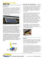
Flexible solar cells
Polymer based amorphous flexible solar
cells are interesting in that you can attach
them to backpacks and articles of clothing like
jackets or hats. They are handy for special
applications like model building, planes trains,
dirigibles, balloons and model rockets for high
altitude experimentation, robotics and in gener
-
al where you need flexibility to mount them on
curved surfaces. These are available in either
low efficiency silicon or high efficiency non-sili
-
con thin film.
Amorphous flexible solar cell
Copyright ©2007
Phillip Hurley and
Good Idea Creative Services
ALL RIGHTS RESERVED
7
Solar Cells
Crystalline solar cells
There are two types of crystalline solar cells: polycrystalline and monocrystalline.
Crystalline solar cells are produced mainly by the Siemens process,
the Czochralskie process, and ribbon process. In the Siemens process,
trichlorosilane, or silane is fed along with hydrogen into a chamber in which
slender rods of electronic grade silicon are heated to over 1000°C. This process
produces a polycrystalline ingot.
In the Czochralskie process, silicon chunks are heated to over 1000°C and a
seed crystal is put into the melt and raised slowly while being rotated. The silicon
solidifies and forms a single crystal growth. This produces a monocrystalline ingot.
Another method is the ribbon forming process in which strings are pulled
through a container of molten silicon. The molten silicon solidifies between the
strings and forms a continuous ribbon.
In each process, after the crystal is formed, it must be cut into wafers and/or
cut to size, polished, etched, and a PN junction formed. Then, the front electrodes
and back contacts are applied. Finally, an anti-reflective coating is applied.
In this book we will focus on the use of polycrystalline and monocrystalline
solar cells for building solar panels because they are easy to work with, are
most readily available in the secondary market, and provide a good power output
that is cost effective.
Copyright ©2007
Phillip Hurley and
Good Idea Creative Services
ALL RIGHTS RESERVED
8
Solar Cells
Monocrystalline and polycrystalline cells
Polycrystalline and monocrystalline cells generally have an efficiency of 8%
to 15%. Of these two types of silicon cells, the single crystal (monocrystalline)
cell produces more current from a
given area of exposed surface than
the same area on a polycrystalline
cell. Single crystal cells are also
more expensive to manufacture.
This is of course reflected in the
cost of the cells to the end buyer.
Polycrystalline cell, above;
Monocrystalline cell, below
Magnified surface of
polycrystalline cell
Copyright ©2007
Phillip Hurley and
Good Idea Creative Services
ALL RIGHTS RESERVED
9
Solar Cells
Either of these types of cells
is fine for the construction of
solar panels, but if you want
to get the most power from a
given amount of space, use
monocrystalline cells.
Both poly- and mono-
crystalline cells come in several
shapes and many sizes. The
basic cell shapes are round,
square, pseudo-square and
rectangle. Cells can be cut to
just about any size needed by
the manufacturer.
New cells vs. old-style cells
The structure of photovoltaic cells has changed over time. They are becoming
thinner, which makes them less expensive to make since the manufacturer can
get more cells from a given amount of silicon and other active materials in the
ingot, ribbon, or deposition process. The cells are now easier and less costly to
manufacture, but they are much more fragile and delicate than the older cells,
and require much more care in handling and soldering.
Various solar cell shapes. Top left to right,
rectangle, pseudo-square; three round cells
on the right; and bottom left, two square cells.
Copyright ©2007
Phillip Hurley and
Good Idea Creative Services
ALL RIGHTS RESERVED
10
Solar Cells
The electrode contacts are also becoming thinner.
The older cells, usually round in shape, have heavy
solder contacts on the front side of the cells, and the
backs are usually totally covered with solder. Cells
made today have just thin lines or spots of solder
that are usually vapor deposited or silk screened
onto the cell.
Solar cell output
Solar cells all produce about 0.5 volts, more or
less, no matter how large they are. However, the size
of the cell does affect the current output. The larger
the surface area of the cell, the more current it will
produce. A 2
"
square cell will produce less current
than a cell that is 4
"
square, all other parameters
being equal. This is important to consider when you
design panels for a specific purpose. If you need a
lot of battery charging power (amps), your panels
should have high current output cells. If your power
needs are minimal and/or you live in a fairly sunny
climate, you can do well with lower current cells.
Above, older style cells,
with solder covering the
backs; below, newer cell
with six solder spots on
the back.
Copyright ©2007
Phillip Hurley and
Good Idea Creative Services
ALL RIGHTS RESERVED
11
Solar Cells
Cells with high current output are generally more desirable; but, the higher the
current output, the more they will cost. High current cells will recharge batteries
faster in less than perfect solar power conditions, such as in a climate prone to
cloud cover, or during winter months when the sun is low on the horizon and less
light is available daily. So, seasonal and local climate conditions should be consid
-
ered when selecting the cells to use for building a panel.
Another very important consideration is how much energy will be drawn
from the batteries on a daily basis, and thus how much the batteries are being
drained, and how much time will be required to recharge them each day.
Watt rating of solar cells
When looking for solar cells, notice that a voltage rating and a current rat-
ing (amperage) is given. These figures are called open circuit voltage and short
circuit current ratings. If you multiply the current by the voltage you will get the
watt power rating of the cell. For instance, a cell with a voltage rating of 0.5 volts
and a current rating of 4 amps is rated as a 2 watt cell.
Generally cells range from milliamps on up to 6 amps output. For most practi
-
cal projects a 1 to 4 amp cell will suffice. Two to three amp cells are more com
-
monly used and are the most readily available at a decent price.
Copyright ©2007
Phillip Hurley and
Good Idea Creative Services
ALL RIGHTS RESERVED
12
Solar Cells
Testing solar cells
Solar cells are tested by the manufacturer
with artificial light under what is called AM1
conditions. AM stands for air mass. Air mass
is the amount of air the photons have to travel
through before they reach the surface of the
earth at sea level. Air mass 1 is when the sun
is directly overhead at sea level. The energy
available to the solar cell at AM1 is equivalent
to about 1kW/m
2
.
Match solar cell output
You need to test each and every cell that will be used in your panel. If you are
dealing with off-spec cells, the cells must be grouped into categories of high,
medium, and low output. If you include a low output cell in a panel with cells
that are higher output, the low output cell will bring all the other cells down to
its lower rating. They don’t have to all have the same dead-on output, but they
should be in the ballpark for what you want the panel to produce. One cell that is
of very low output can deprive you of a lot of energy from the other cells.
90°
60°
45°
30°
1
1.15
2
sea level
1.41
Air mass conditions
Copyright ©2007
Phillip Hurley and
Good Idea Creative Services
ALL RIGHTS RESERVED
13
Solar Cells
Cells can be tested in the sun on a very clear day. The ideal time to test
cells outdoors is during the summer when the sun is at its highest point around
the solstice, and at solar noon. This gets you the closest to AM1 conditions.
However, you can test your cells using the sun at any time of the year. If you do
this, take into consideration that the out
-
put from the cells will be less than their
peak output under ideal conditions.
Any light conditions can be used to tell
how well the cells perform in comparison
to each other, since you don’t need to
know their peak output for matching. The
comparison of each cell’s output to the
others is really the critical issue.
Tools for testing solar cells
To test the cells you will need a
multimeter that gives a current (amper
-
age) reading and a voltage reading. All
multimeters have these two readings
available. It’s also useful to make a stand
that will hold the cells at the same angle
Stand for testing solar cells
Copyright ©2007
Phillip Hurley and
Good Idea Creative Services
ALL RIGHTS RESERVED
14
Solar Cells
as the sun above the horizon, and that can be pointed in the direction of the
sun. You can just hold the cells with your hands, but this can be clumsy.
My testing stand has a piece of copper clad circuit board to lay the cells on.
With this arrangement I can connect the multimeter with the back of the cell sim
-
ply by touching the multimeter probe to the copper on the circuit board. With this
method, however, you have to be sure that the contacts on the back surface of
the cell connect well with the copper on the board.
To take a reading, touch the negative probe to one of the cell fingers on the
face of the cell and touch the other (positive) probe, to the back of the cell (or
the copper surface of the circuit board if you are using one). The cell should be
facing in the direction of the sun and at the sun’s angle. Take both the voltage
and current reading for the cell, and write it down. Proceed similarly with the
other cells, grouping them as you go along.
Test all of your cells on the same day. If you test the same cell on two differ
-
ent clear days, you may get quite different readings, although conditions one day
might appear to be the same as the other day, there can be a significant differ
-
ence in available sunlight due to the level of aerosols present. Particulates,
Copyright ©2007
Phillip Hurley and
Good Idea Creative Services
ALL RIGHTS RESERVED
15
Solar Cells
moisture, general pollution, and pollen all
affect cell output readings. With repeated
observations, you will be able to discern the
aerosol levels in the atmosphere.
Using a calibrated cell
One way to measure light intensity when
working with solar cells and panels is to use
a calibrated cell. This is simply a photovoltaic
cell that has been exposed to artificial AM1/full
sun (1kW/m2) condition light, and the output marked on the back of the cell. The
calibrated cell can be used to indicate what percentage of AM1 conditions you
have when testing other cells and panels. For instance, if the current output of
the calibrated cell under AM1 conditions is two amps, if you get a reading of one
amp, it indicates that light conditions are 50% or
2
AM1.
To test cells using a calibrated cell, write down the calibrated cell reading and
then write down current readings for the cells being tested. This will indicate
what your cell output is for a specific light condition. Since the output of a silicon
solar cell is linear you can extrapolate from this reading what your cells will out
-
put at different percentages of AM1.
Calibrated solar cell
Copyright ©2007
Phillip Hurley and
Good Idea Creative Services
ALL RIGHTS RESERVED
16
Solar Cells
A calibrated cell can be purchased from one of the suppliers listed in the sup-
pliers list on page 137. They are also excellent for comparing the performance
of different types or lots of cells that you may have so that you can discern
which cells to use for different projects.
When testing single cells with a calibrated cell, you need a fixture like the test
stand shown on page 13 to hold both the calibrated cell and the cell being tested
at the same position and angle to the sun. This can be as simple as a flat board.
Copyright ©2007
Phillip Hurley and
Good Idea Creative Services
ALL RIGHTS RESERVED
17
Solar Panels
Solar panel output for different applications
Most simple series connected solar panels are rated into three categories:
15 to 16 volts – usually 30 to 32 cells per panel
16.5 to 17 volts – 33 to 34 cells per panel
17.5 to 21 volts – 35 to 36 cells per panel
15 to 16 volt panels are referred to as self-regulating panels because they do
not produce enough voltage to overcharge batteries, which results in gassing.
For this reason they do not require a charge regulator as the other panels do.
This reduces the cost and maintenance of a system. These are referred to as
battery maintainers, and are excellent to use in small system with one battery if
the system does not have much of a power drain. Electric fences, and other low
power applications that have limited energy use can use these types of panels.
16.5 to 17 volt panels are adequate for full fledged powers systems in loca
-
tions that generally get a lot of sun year round, such as the US Southwest.
The preferred panel for most solar charging applications is a 35 to 36 cell panel
which delivers from 17.5 to 21 volts open circuit voltage. A 36 cell panel is recom
-
mended for very hot climates in order to offset power output loss from high tem
-
perature. They also compensate for voltage drop in systems with long wire runs.
p
p
p
Copyright ©2007
Phillip Hurley and
Good Idea Creative Services
ALL RIGHTS RESERVED
18
Solar Panels
I usually construct panels with 36 cells for basic 12 volt lead acid battery
charging. One of the great advantages of building solar panels is that they can
be built to exactly the voltage and current needed for your project by adjusting
the type and quantity of cells.
Solar panel ratings
Solar panels are rated in many different ways. The ratings provide a baseline
to project what the power output could be under a variety of different conditions.
Some of the designations that manufacturers use are Wp (peak watts) and Pmax
(maximum power).
If you use off-spec cells in your panels you will not know where a panel will
land in the IV or voltage current curve until it is finished and you can test it.
Each cell in the panel may output slightly different voltage and current, and they
will all be added or subtracted together for the whole panel’s output.
When the finished panel is tested, you will have a better, although still not
perfect, reading of its output. The reason it will not be perfect is that you will
probably not be testing the panel under laboratory conditions where temperature
and light intensity are absolutely controlled. This is not too much of a concern
since most laboratory panel tests do not reveal real working conditions, anyway.
Very few panels will see laboratory AM1 conditions in service, nor will they be
Copyright ©2007
Phillip Hurley and
Good Idea Creative Services
ALL RIGHTS RESERVED
19
Solar Panels
in the constant even temperature on which the ratings are based. So, remember
that there is a discrepancy between real life working conditions and the rated
output of commercial panels.
The truth is you will never know how a panel will perform until it is installed in
the system where it will be in service. The output of a particular panel or array
depends a lot on the battery load. Each type of battery acts differently and has
different internal resistances and so on. The variables go on and on. In a tropical
location with lots of sun you might think a panel would be near optimum output,
but in fact heat above a certain point usually reduces performance as output is
temperature sensitive.
Designer watts
In designing panels with off-spec and blemished cells you will only be con-
cerned with what we call “designer watts.
” Designer wattage is simply the open
circuit voltage multiplied by the short circuit current. Panel designers use this
figure to rate the components used in the panel and peripheral components
For instance, if a panel delivers about 20 volts open circuit and 3.5 amps
short circuit current, the designer wattage would be 70 watts. The system com
-
ponents must be able to handle 70 watts, at 3.5 amps and 20 volts.
Copyright ©2007
Phillip Hurley and
Good Idea Creative Services
ALL RIGHTS RESERVED