Programmable logic controllers 5ed P3
Bạn đang xem bản rút gọn của tài liệu. Xem và tải ngay bản đầy đủ của tài liệu tại đây (1.43 MB, 50 trang )
4.4.2 Network Standards
Interconnecting several devices can present problems of compatibility; for example, they
may operate at different baud rates or use different protocols. To facilitate communications
between devices, the International Standards Organization (ISO) in 1979 devised a model to
be used for standardization for open systems interconnection (OSI); the model is termed the
ISO OSI model. A communication link between items of digital equipment is defined in
terms of physical, electrical, protocol, and user standards, the ISO OSI model breaking this
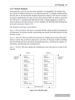
down into seven layers ( Figure 4.29).
The function of each layer in the model is:
Layer 1: Physical medium. This layer is concerned with the coding and physical transmission
of information. Its functions include synchronizing data transfer and transferring bits of data
between systems.
Layer 2: Data link. This layer defines the protocols for sending and receiving information
between systems that are directly connected to each other. Its functions include assembling
bits from the physical layer into blocks and transferring them, controlling the sequence of
data blocks, and detecting and correcting errors.
Layer 3: Network. This layer defines the switching that routes data between systems in the
network.
Layer 7
Application
Layer 6
Presentation
Layer 5
Session
Layer 4
Transport
Layer 3
Network
Layer 2
Data link
Layer 1
Physical medium
System 1
Layer 7
Application
Layer 6
Presentation
Layer 5
Session
Layer 4
Transport
Layer 3
Network
Layer 2
Data link
Layer 1
Physical medium
System 2
Transmission path
Application
program
Application
program
Figure 4.29: ISO/OSI model.
www.newnespress.com
I/O Processing 97
Layer 4: Transport. This layer defines the protocols responsible for sending messages from
one end of the network to the other. It controls message flow.
Layer 5: Session. This layer provides the function to set up communications between users
at separate locations.
Layer 6: Presentation. This layer ensures that information is delivered in an understandable
form.
Layer 7: Application. This layer has the function of linking the user program into the
communication process and is concerned with the meaning of the transmitted information.
Each layer is self-contained and only deals with the interfaces of the layer immediately above
and below it; it performs its tasks and transfers its results to the layer above or the layer
below. It thus enables manufacturers of products to design products operable in a particular
layer that will interface with the hardware of other manufacturers.
To illustrate the function of each layer, consider the analogy of making a telephone call. The
physical medium is the telephone line, and layer 1 has to ensure that the voice signal is
converted into an electrical signal for transmission and then, at the other end of the line, back
into an electrical signal. Layer 1 thus defines the types of connectors and the signal levels
required. Layer 2 ensures that words that are not clearly received are transferred back to the
sender for retransmission. Layer 3 provides the mechanism for dialing the number of the
person to be called to make the connection between sender and receiver. Layer 4 is used to
ensure that the messages are transmitted without loss. Layer 5 provides the protocols that
can be used to set up a call between specific individuals—for example, for someone in an
office to be brought to the telephone. Layer 6 resolves the problem of language so that both
caller and receiver are speaking the same language. Layer 7 gives the procedures that are
to be adopted for conveying particular pieces of information, such as the quantity to be
ordered followed by the reference number of the product in a catalog.
In 1980, the Institute of Electronic and Electrical Engineers (IEEE) began Project 802. This is
a model that adheres to the OSI Physical layer but that subdivided the Data link layer into
two separate layers: the Media Access Control (MAC) layer and the Logical Link Control
(LLC) layer. The MAC layer defines the access method to the transmission medium and
consists of a number of standards to control access to the network and ensure that only
one user is able to transmit at any one time. One standard is IEEE 802.3 Carrier Sense
Multiple Access and Collision Detection (CSMA/CD); stations have to listen for other
transmissions before being able to gain control of the network and transmit. Another standard
is IEEE 802.4 Token Passing Bus; with this method a special bit pattern, the token, is
circulated, and when a station wants to transmit, it waits until it receives the token and
then attaches it to the end of the data. The LLC layer is responsible for the reliable
transmission of data packets across the Physical layer.
www.newnespress.com
98 Chapter 4
4.5 Examples of Commercial Systems
The following are examples of systems that may be met with installations involving PLCs.
4.5.1 MAP
By 1990 General Motors in the United States had a problem automating its manufacturing
activities; the company needed all its systems to be able to talk to each other. It thus
developed a standard communications system for factory automation applications, called the
manufacturing automation protocol (MAP). The system applied to all systems on the shop
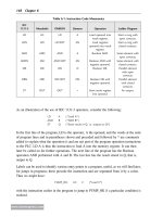
floor, such as robot systems, PLCs, and welding systems. Table 4.3 shows the MAP model
and its relationship to the ISO model. In order for non-OSI equipment to operate on the
MAP system, gateways may be used. These are self-contained units or interface boards
that fit in the device so that messages from a non-OSI network/device may be transmitted
through the MAP broadband token bus to other systems.
The Application layer supports the Manufacturing Message Service (MMS), which defines
the interactions between PLCs and numerically controlled machines and robots.
For the data link, methods are needed to ensure that only the user of the network is able to
transmit at any one time, and for MAP the method used is token passing. The term
broadband is used for a network in which information is modulated onto a radio frequency
carrier that is then transmitted through the coaxial cable.
MAP is not widely used; a more commonly used system is the Ethernet. This is a single
bus system with CSMA/CD used to control access. It uses coaxial cable with a maximum
length of 500 m; up to 1024 stations can be accommodated, and repeaters that restore
signal amplitude, waveform, and timing can be used to extend this capability (Figure 4.30).
Each station is connected to the bus via a transceiver, which clamps onto the bus cable.
Table 4.3: MAP
ISO Layer MAP
7 Application ISO file transfer, MMS, FTAM, CASE
6 Presentation
5 Session ISO session kernel
4 Transport ISO transport class 4
3 Network ISO Internet
2 Data link IEEE 802.2 class 1; IEEE 802.4 token bus
1 Physical IEEE 802.4 broadband
Transmission 10 mbps coaxial cable with RF modulators
Note: MMS ¼ manufacturing message service, FTAM ¼ file transfer, CASE ¼
common applications service; each of these provides a set of commands that will be
understood by devices and the software used.
www.newnespress.com
I/O Processing 99
The term vampire tap is used for the clamp on to the cable since stations can be connected or
removed without disrupting system operation.
The term baseband is used when the signal is transmitted as just a series of voltage levels
directly representing the bits being transmitted.
4.5.2 Ethernet
Ethernet does not have a master station, each connected station being of equal status, and
so we have peer-to-peer communication. A station that wants to send a message on the bus
will determine whether the bus is clear and, when it is, put its message frame on the bus.
There is the slight probability that more than one station will sense an idle bus and attempt
to transmit. Thus each sender monitors the bus during transmission and detects when the
signal on the bus does not match its own output. When such a “collision” is detected, the
transmission continues for a short while in order to give time to other stations to detect
the collision and then the station attempts to retransmit at a later time. Each message includes
a bit sequence to indicate the destination address, source address, the data to be transmitted,
and a message check sequence. The message check sequence contains the cycle redundancy
check (see Section 4.3.4). At each receiving station the frame’s destination address is
checked to determine whether the frame is destined for it. If so, it accepts the message.
Ethernet is widely used where systems involve PLCs having to communicate with
computers. The modular Allen-Bradley PLC-5 can be configured for use with a range of
communication networks by the addition of suitable modules (refer back to Figure 1.15),
including a module enabling use with Ethernet. Ethernet is faster than MAP because the
token-passing method of MAP is slower than the method used with Ethernet. PLC
manufacturers often have their own networks, in addition to generally offering the option
of Ethernet.
Station Station
Station Station
Terminato
r
Repeater
Transceiver
Transceiver
Cable
Cable
Terminato
r
Maximum length 500 m
Tranceiver
Tranceiver
Tranceiver
Tranceiver
Figure 4.30: Baseband Ethernet with repeaters.
www.newnespress.com
100 Chapter 4
4.5.3 ControlNet
This is a network used by Allen-Bradley. Data is placed on the network with no indication as
to who it is for. All the stations using this data can thus simultaneously accept it at the same
time. This reduces the number of messages needed to be placed on the network and so
increases the network speed. This allows PLC racks and their data to be shared equally
among several processors and not be just dedicated to one. Network access is controlled by a
timing algorithm called Concurrent Time Domain Multiple Access (CTDMA), which
determines a node’s ability to transmit in the network.
4.5.4 DeviceNet
This is based on the Controller Area Network (CAN), a system that has been widely used
with cars (see Section 4.3.2). Each device in the network is requested to send or receive an
update of its status, with generally each being requested to respond in turn. Devices are
configured to automatically send messages at scheduled intervals, otherwise sending
messages only when their status changes. DeviceNet is generally a subnetwork of a PLC that
is connected to an Ethernet or ControlNet network and is used to link devices such as sensors,
motor starters, and pneumatic valves.
4.5.5 Allen-Bradley Data Highway
The Allen-Bradley d ata h ighway is a peer-to-peer system developed f or A llen-Brad ley PLC s
and uses tok en pas sing to c ontro l mes sage tran smission. Th e s tation a ddresses o f e ach P LC are se t
by switches on each PLC. Co mmunication is establi shed by a single message on the d ata highway,
specifying the sending a nd receiving addresses and the l ength o f b lock to be transferred.
4.5.6 PROFIBUS
Process Field Bus (PROFIBUS) is a system that was developed in Germany and is used by
Siemens with its PLCs. PROFIBUS DP (Decentralized Periphery) is a device-level bus that
usually operates with a single DP master and several slaves. Several such DP systems can be
installed on one PROFIBUS network. The transmissions are via RS485 (similar to RS422; see
Section 4.3.2) or glass fiber optics. Such a system is comparable to DeviceNet. PROFIBUS PA
(Process Automation) is an extension of PROFIBUS DP for data transmission from devices
such as sensors and actuators. PROFIBUS DP can be connected to PROFIBUS PA using a DP/
PA coupler if the work can be operated at 45.45 kbits/s; otherwise a DP/PA link has to be used
to convert the data transfer rate of PROFIBUS DP to that of PROFIBUS PA.
4.5.7 Factory-Floor Network
A factory-floor network can use a number of network systems. Thus there may be Ethernet to
provide the information layer for data collections and program maintenance, with the next
layer down being ControlNet, to deal with real-time input/output processing, and, at the
www.newnespress.com
I/O Processing 101
lowest layer, DeviceNet, to deal with sensors and drives. PLCs would take instructions from
the Ethernet layer and exercise control through the ControlNet layer.
4.6 Processing Inputs
A PLC is continuously running through its program and updating it as a result of the input
signals. Each such loop is termed a cycle. PLCs could be operated by each input being
examined as it occurred in the program, its effect on the program determined, and the output
correspondingly changed. This mode of operation is termed continuous updating.
Because there is time spent interrogating each input in turn with continuous updating, the
time taken to examine several hundred input/output points can become comparatively long.
To allow more rapid execution of a program, a specific area of RAM is used as a buffer store
between the control logic and the input/output unit. Each input/output has an address in this
memory. At the start of each program cycle the CPU scans all the inputs and copies their
status into the input/output addresses in RAM. As the program is executed, the stored input
data is read, as required, from RAM and the logic operations are carried out. The resulting
output signals are stored in the reserved input/output section of RAM. At the end of each
program cycle all the outputs are transferred from RAM to the appropriate output channels.
The outputs then retain their status until the next updating. This method of operation is
termed mass I/O copying. The sequence can be summarized as follows (Figure 4.31):
1. Scan all the inputs and copy into RAM.
2. Fetch, decode, and execute all program instructions in sequence, copying output
instructions to RAM.
3. Update all outputs.
4. Repeat the sequence.
Scan all
inputs
Update
outputs
Carry out
program
Repeat
sequence
Figure 4.31: PLC operation.
www.newnespress.com
102 Chapter 4
The time taken to complete a cycle of scanning inputs and updating outputs according to the
program instructions, that is, the cycle time, though relatively quick, is not instantaneous and
means that the inputs are not watched all the time, but instead that samples of their states are
taken periodically. A typical cycle time is on the order of 10 to 50 ms. This means that the
inputs and outputs are updated every 10 to 50 ms and thus there can be a delay of this order
in the system reaction. It also means that if a very brief input cycle appears at the wrong
moment in the cycle, it could be missed. In general, any input must be present for longer than
the cycle time. Special modules are available for use in such circumstances.
Consider a PLC with a cycle time of 40 ms. What is the maximum frequency of digital
impulses that can be detected? The maximum frequency will be if one pulse occurs every
40 ms, that is, a frequency of 1/0.04 ¼ 25 Hz.
The cycle or scanning time for a PLC, i.e. its response speed, is determined by:
1. The CPU used.
2. The size of the program to be scanned.
3. The number of inputs/outputs to be read.
4. The system functions that are in use; the greater the number, the slower the scanning
time.
As an illustration, the Mitsubishi compact PLC, MELSEC FX3U (see Section 1.4), has a
quoted program cycle time of 0.065 ms per logical instruction. Thus the more complex the
program, the longer the cycle time will be.
4.7 I/O Addresses
The PLC has to be able to identify each particular input and output. It does this by allocating
addresses to each input and output. With a small PLC this is likely to be just a number,
prefixed by a letter to indicate whether it is an input or an output. Thus for the Mitsubishi
PLC we might have inputs with addresses X400, X401, X402, and so on and outputs with
addresses Y430, Y431, Y432, and so on, the X indicating an input and the Y an output.
Toshiba uses a similar system.
With larger PLCs that have several racks of input and output channels, the racks are
numbered. With the Allen-Bradley PLC-5, the rack containing the processor is given the
number 0 and the addresses of the other racks are numbered 1, 2, 3, and so on, according to
how setup switches are set. Each rack can have a number of modules, and each one deals
with a number of inputs and/or outputs. Thus addresses can be of the form shown in
Figure 4.32. For example, we might have an input with address I:012/03. This would indicate
an input, rack 01, module 2, and terminal 03.
www.newnespress.com
I/O Processing 103
With the Siemens SIMATIC S5, the inputs and outputs are arranged in groups of eight. Each
such group is termed a byte, and each input or output within a group of eight is termed a bit.
The inputs and outputs thus have their addresses in terms of the byte and bit numbers,
effectively giving a module number followed by a terminal number, a full stop (.) separating
the two numbers. Figure 4.33 shows the system. Thus I0.1 is an input at bit 1 in byte 0, and
Q2.0 is an output at bit 0 in byte 2.
The GEM-80 PLC assigns inputs and output addresses in terms of the module number and
terminal number within that module. The letter A is used to designate inputs, and B outputs.
Thus A3.02 is an input at terminal 02 in module 3, and B5.12 is an output at terminal
12 in module 5.
In addition to using addresses to identify inputs and outputs, PLCs also use their
addressing systems to identify internal, software-created devices, such as relays, timers, and
counters.
Summary
The input/output units of PLCs are designed so that a range of input signals can be changed
into 5 V digital signals and a range of output signals are available. For a PLC input unit with
sourcing, it is the source of the current supply for the input device connected to it; with
sinking, the input device provides the current to the input unit. For a PLC output unit with
sourcing, it provides the current to the output device, and for sinking, the output device
produces the current for the PLC output. Output units can be relay, transistor, or triac.
For inputs, signal conditioning is generally used to convert analog signals to a current in the
range 4 to 20 mA and, thus, by passing through a 250 O resistor, to a 1 to 5 V input signal.
This might be achieved by a potential divider or perhaps an operational amplifier. An
X: X X X / X X
I = input
O = output
Rack number
Module number
Terminal number
Figure 4.32: Allen-Bradley PLC-5 addressing.
X X X . X
I = input
Q = output
Byte number
Bit numbe
r
Figure 4.33: Siemens SIMATIC S5 addressing.
www.newnespress.com
104 Chapter 4
operational amplifier can be used to compare two signals and give an on/off signal based on
their relative values.
Serial communication is when data is transmitted one bit at a time. Parallel
communication occurs when a data word is separated into its constituent bits and each bit
is simultaneously transmitted along parallel cables. The most common serial standard is
RS232; other standards are RS422 and RS423. The 20 mA loop can be used for serial
communication. The most common parallel standard interface is IEEE-488. Protocols are
necessary to exercise control of the flow of data between devices. The most commonly used
code for the transmission of characters is ASCII.
The term local area network (LAN) describes a communications network designed to link
computers and their peripherals within the same building or site. Networks can take three
forms: star, bus, or ring. Often PLCs figure in a hierarchy of communications, with input and
output devices at the lowest level, at the next level small PLCs or computers, and at the next
level, larger PLCs and computers. The ISO OSI model has been devised for standardization
for open systems interconnection. Examples of commercial network systems are MAP,
Ethernet, ControlNet, DeviceNet, Allen-Bradley Data Highway, and PROFIBUS.
A PLC is continuously running through its program and updating it. It does this by mass I/O
copying, in which all the inputs are scanned and copied into RAM, then fetched and decoded,
and all program instructions are executed in sequence and output instructions copied to
RAM. Then all the outputs are updated before repeating the sequence. The PLC has to be
able to identify each particular input and output, and it does this by allocating addresses to
each input and output.
Problems
Problems 1 through 15 have four answer options: A, B, C, or D. Choose the correct answer
from the answer options.
1. An ADC is used to sample the output voltage from a pressure sensor. If the output from
the sensor is 0 V when the pressure is 0 kPa and 10 V when it is 10 kPa, the minimum
number of ADC bits needed to resolve the sensor output if the sensor error is not to
exceed 0.01 kPa is:
A. 4
B. 8
C. 10
D. 12
2. A 12-bit ADC can be used to represent analog voltages over its input range with:
A. 12 different binary numbers
B. 24 different binary numbers
www.newnespress.com
I/O Processing 105
C. 144 different binary numbers
D. 4096 different binary numbers
3. For an analog input range of 0 to 10 V, the minimum size ADC needed to register a
change of 0.1 V is:
A. 4-bit
B. 6-bit
C. 8-bit
D. 12-bit
4. An inverting operational amplifier circuit has an input resistance of 10 kO and feedback
resistance of 100 kO. The closed-loop gain of the amplifier is:
A. –100
B. –10
C. þ10
D. þ100
Problems 5 and 6 refer to an operational amplifier with a closed loop gain of 100 and an input
resistance of 47 kO.
5. The feedback resistor for an inverting op-amp amplifier will be:
A. 4.65 kO
B. 4.7 kO
C. 465 kO
D. 470 kO
6. The feedback resistor for a noninverting op-amp amplifier will be:
A. 4.65 kO
B. 4.7 kO
C. 465 kO
D. 470 kO
7. Decide whether each of these statements is true (T) or false (F). A serial communication
interface:
(i) Involves data being transmitted and received one bit at a time.
(ii) Is a faster form of transmission than parallel communication.
A. (i) T (ii) T
B. (i) T (ii) F
C. (i) F (ii) T
D. (i) F (ii) F
www.newnespress.com
106 Chapter 4
8. Decide whether each of these statements is true (T) or false (F). The RS232
communications interface:
(i) Is a serial interface.
(ii) Is typically used for distances up to about 15 m.
A. (i) T (ii) T
B. (i) T (ii) F
C. (i) F (ii) T
D. (i) F (ii) F
Problems 9 and 10 refer to the following, which shows the bits on an RS232 data line being
used to transmit the data 1100001:
0110000111
XYZ
9. Decide whether each of these statements is true (T) or false (F). The extra bits X and Z at
the beginning and the end are:
(i) To check whether the message is corrupted during transmission.
(ii) To indicate where the data starts and stops.
A. (i) T (ii) T
B. (i) T (ii) F
C. (i) F (ii) T
D. (i) F (ii) F
10. Decide whether each of these statements is true (T) or false (F). Bit Y is:
(i) The parity bit showing odd parity.
(ii) The parity bit showing even parity.
A. (i) T (ii) T
B. (i) T (ii) F
C. (i) F (ii) T
D. (i) F (ii) F
11. Decide whether each of these statements is true (T) or false (F). The parallel data
communication interface:
(i) Enables data to be transmitted over short distances at high speeds.
(ii) Has a common standard known as IEEE-488.
A. (i) T (ii) T
B. (i) T (ii) F
C. (i) F (ii) T
D. (i) F (ii) F
www.newnespress.com
I/O Processing 107
12. Decide whether each of these statements is true (T) or false (F). For communications
over distances of the order of 100 to 300 m with a high transmission rate:
(i) The RS232 interface can be used.
(ii) The 20 mA current loop can be used.
A. (i) T (ii) T
B. (i) T (ii) F
C. (i) F (ii) T
D. (i) F (ii) F
13. Decide whether each of these statements is true (T) or false (F). With input/output
processing, mass input/output copying:
(i) Scans all the inputs and copies their states into RAM.
(ii) Is a faster process than continuous updating.
A. (i) T (ii) T
B. (i) T (ii) F
C. (i) F (ii) T
D. (i) F (ii) F
14. The cycle time of a PLC is the time it takes to:
A. Read an input signal.
B. Read all the input signals.
C. Check all the input signals against the program.
D. Read all the inputs, run the program, and update all outputs.
15. Decide whether each of these statements is true (T) or false (F). A PLC with a long cycle
time is suitable for:
(i) Short duration inputs.
(ii) High-frequency inputs.
A. (i) T (ii) T
B. (i) T (ii) F
C. (i) F (ii) T
D. (i) F (ii) F
16. Specify (a) the odd parity bit and (b) the even parity bit to be used when the data
1010100 is transmitted.
17. Explain the purpose of using a parity bit.
18. Explain the continuous updating and the mass input/output copying methods of
processing inputs/outputs.
19. What input resistance and feedback resistance can be used with an inverting operational
amplifier circuit to give a gain of –100?
www.newnespress.com
108 Chapter 4
20. Compare the star, bus and ring forms of network and the methods used to avoid problems
with messages.
21. What are the functions of (a) PROFIBUS DP and PROFIBUS PA, (b) ControlNet, and
DeviceNet?
22. A network is said to involve token passing. What does this mean?
Lookup Tasks
23. Look up the network systems that the PLCs of a particular manufacturer are designed to
operate with.
www.newnespress.com
I/O Processing 109
CHAPTER 5
Ladder and Functional Block
Programming
Programs for microprocessor-based systems have to be loaded in machine code, a sequence
of binary code numbers to represent the program instructions. However, assembly language
based on the use of mnemonics can be used; for example, LD is used to indicate the
operation required to load the data that follows the LD, and a computer program called an
assembler is used to translate the mnemonics into machine code. Programming can be made
even easier by the use of the so-called high-level languages, such as C, BASIC, Pascal,
FORTRAN, and COBOL. These languages use prepackaged functions, represented by
simple words or symbols descriptive of the function concerned. For example, with C
language the symbol & is used for the logic AND operation. However, the use of these
methods to write programs requires some skill in programming, and PLCs are intended to be
used by engineers without any great knowledge of programming. As a consequence, ladder
programming (LAD) was developed as a means of writing programs that can then be
converted into machine code by software for use with the PLC microprocessor. This method
of writing programs became adopted by most PLC manufacturers, but each tended to
develop its own version, and so an international standard has been adopted for ladder
programming and, indeed, all the methods used for programming PLCs. The standard,
published in 1993, is IEC 1131-3 (see Section 1.4.2). Functional block programming (FBD)
is another method of programming.
This chapter is an introduction to programming a PLC using ladder diagrams and functional
block diagrams. Here we are concerned with the basic techniques involved in developing
ladder and function block programs to represent basic switching operations involving the
logic functions of AND, OR, EXCLUSIVE OR, NAND, and NOR, as well as latching. Later
chapters continue with ladder programming involving other elements.
5.1 Ladder Diagrams
As an introduction to ladder diagrams, consider the simple wiring diagram for an electrical
circuit in Figure 5.1a. The diagram shows the circuit for switching on or off an electric
motor. We can redraw this diagram in a different way, using two vertical lines to represent
©
2009 Elsevier Ltd. All rights reserved.
doi: 10.1016/B978-1-85617-751-1.00005-7
111
the input power rails and stringing the rest of the circuit between them. Figure 5.1b shows the
result. Both circuits have the switch in series with the motor and supplied with electrical
power when the switch is closed. The circuit shown in Figure 5.1b is termed a ladder
diagram.
With such a diagram, the power supply for the circuits is always shown as two vertical lines,
with the rest of the circuit as horizontal lines. The power lines, or rails, as they are often
called, are like the vertical sides of a ladder, with the horizontal circuit lines similar to the
rungs of the ladder. The horizontal rungs show only the control portion of the circuit; in
the case of Figure 5.1b it is just the switch in series with the motor. Circuit diagrams often
show the relative physical location of the circuit components and how they are actually
wired. With ladder diagrams, no attempt is made to show the actual physical locations, and
the emphasis is on clearly showing how the control is exercised.
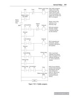
Figure 5.2 shows an example of a ladder diagram for a circuit that is used to start and stop a
motor using push buttons. In the normal state, push button 1 is open and push button 2 closed.
When button 1 is pressed, the motor circuit is completed and the motor starts. Also, the
holding contacts wired in parallel with the motor close and remain closed as long as the
motor is running. Thus when the push button 1 is released, the holding contacts maintain the
circuit and hence the power to the motor. To stop the motor, push button 2 is pressed. This
disconnects the power to the motor, and the holding contacts open. Thus when push button 2
is released, there is still no power to the motor. Thus we have a motor that is started by
pressing button 1 and stopped by pressing button 2.
M
d.c. input
Switch
Motor
(a)
L1
L2
Power rails
L1
L2
Switch Motor
M
(b)
Figure 5.1: Ways of drawing the same electrical circuit.
L1 L2
M
1
2
Holdin
g
switch
Figure 5.2: Stop/start switch.
www.newnespress.com
112 Chapter 5
5.1.1 PLC Ladder Programming
A very commonly used method of programming PLCs is based on the use of ladder
diagrams. Writing a program is then equivalent to drawing a switching circuit. The ladder
diagram consists of two vertical lines representing the power rails. Circuits are connected as
horizontal lines, that is, the rungs of the ladder, between these two verticals.
In drawing a ladder diagram, certain conventions are adopted:
•
The vertical lines of the diagram represent the power rails between which circuits are
connected. The power flow is taken to be from the left-hand vertical across a rung.
•
Each rung on the ladder defines one operation in the control process.
•
A ladder diagram is read from left to right and from top to bottom. Figure 5.3 shows the
scanning motion employed by the PLC. The top rung is read from left to right. Then the
second rung down is read from left to right and so on. When the PLC is in its run mode, it
goes through the entire ladder program to the end, the end rung of the program being
clearly denoted, and then promptly resumes at the start (see Section 4.4). This procedure
of going through all the rungs of the program is termed a cycle. The end rung might
be indicated by a block with the word END or RET, for return, since the program
promptly returns to its beginning. The scan time depends on the number of runs in the
program, taking about 1 ms per 1000 bytes of program and so typically ranging from
about 10 ms up to 50 ms.
•
Each rung must start with an input or inputs and must end with at least one output. The
term input is used for a control action, such as closing the contacts of a switch. The term
output is used for a device connected to the output of a PLC, such as a motor. As the
Rung 1
Rung 2
Rung 3
Rung 4
END
End rung
Left power
rail
Right power
rail
Power flow
Read the status of
all the inputs and
store in memory
Read the inputs
from memory and
implement the
program, storing
the outputs in
memory
Update all the
outputs
Figure 5.3: Scanning the ladder program.
www.newnespress.com
Ladder and Functional Block Programming 113
program is scanned, the outputs are not updated instantly, but the results stored in
memory and all the outputs are updated simultaneously at the end of the program scan
(see Section 4.6).
•
Electrical devices are shown in their normal condition. Thus a switch that is normally
open until some object closes it is shown as open on the ladder diagram. A switch that is
normally closed is shown closed.
•
A particular device can appear in more than one rung of a ladder. For example, we might
have a relay that switches on one or more devices. The same letters and/or numbers are
used to label the device in each situation.
•
The inputs and outputs are all identified by their addresses; the notation used depends on
the PLC manufacturer. This is the address of the input or output in the memory of the
PLC (see Section 4.6).
Figure 5.4 shows standard IEC 1131-3 symbols that are used for input and output devices.
Some slight variations occur between the symbols when used in semigraphic form and
Semi-graphic form Full graphic form
A horizontal link along which
power can flow
Interconnection of horizontal
and vertical power flows
Left-hand power connection
of a ladder rung
Right-hand power connection
of a ladder rung
Normally open contact
Normally closed contact
Output coil: if the power flow
to it is on then the coil state is on
Figure 5.4: Basic symbols.
www.newnespress.com
114 Chapter 5
when in full graphic, the semigraphic form being the one created by simply typing using
the normal keyboard, whereas the graphic form is the result of using drawing tools. Note
that inputs are represented by various symbols representing normally open or normally
closed contacts. The action of the input is equivalent to opening or closing a switch.
Output coils are represented by just one form of symbol. (More symbols are introduced
in later chapters.) The name of the associated variable with its address is displayed
directly above the symbol (for example, for an input start switch, X400, and for an output
Motor 1, Y430).
To illustrate the drawing of the rung of a ladder diagram, consider a situation where
energizing an output device, such as a motor, depends on a normally open start switch
being activated by being closed. The input is thus the switch and the output the motor.
Figure 5.5a shows the ladder diagram. Starting with the input, we have the normally open
symbol jjfor the input contacts. There are no other input devices and the line terminates
with the output, denoted by the symbol ( ). When the switch is closed, that is, there is an
input, the output of the motor is activated. Only while there is an input to the contacts is
there an output. If there had been a normally closed switch j/j with the output (Figure 5.5b),
there would have been an output until that switch was opened. Only while there was no input
to the contacts would there have been an output.
In drawing ladder diagrams, the names of the associated variable and addresses of each
element are appended to its symbol. The more descriptive the name, the better, such as pump
motor control switch rather than just input, and pump motor rather than just output. Thus
Figure 5.6 shows how the ladder diagram of Figure 5.5a would appear using (a) Mitsubishi,
(b) Siemens, (c) Allen-Bradley, and (d) Telemecanique notations for the addresses. Thus
Figure 5.6a indicates that this rung of the ladder program has an input from address X400 and
an output to address Y430. When connecting the inputs and outputs to the PLC, the relevant
ones must be connected to the terminals with these addresses.
OutputInput
(a)
Input
Output
Output
Input
(b)
Input
Output
Figure 5.5: A ladder rung.
www.newnespress.com
Ladder and Functional Block Programming 115
5.2 Logic Functions
There are many control situations requiring actions to be initiated when a certain combination
of conditions is realized. Thus, for an automatic drilling machine (as illustrated in
Figure 1.1a), there might be the condition that the drill motor is to be activated upon
activation of the limit switches that indicate the presence of the workpiece and the drill
position as being at the surface of the workpiece. Such a situation involves the AND logic
function, condition A and condition B having both to be realized for an output to occur.
This section is a consideration of such logic functions.
5.2.1 AND
Figure 5.7a shows a situation in which an output is not energized unless two normally
open switches are both closed. Switch A and switch B must both be closed, which thus gives
an AND logic situation. We can think of this as representing a control system with two
inputs, A and B (Figure 5.7b). Only when A and B are both on is there an output. Thus if we
use 1 to indicate an on signal and 0 to represent an off signal, for there to be a 1 output,
we must have A and B both 1. Such an operation is said to be controlled by a logic gate, and
the relationship between the inputs to a logic gate and the outputs is tabulated in a form
known as a truth table. Thus for the AND gate we have:
Inputs
OutputAB
00 0
01 0
10 0
11 1
Input
X400
(a)
(c)
(b)
(d)
Y430
10.0
Q2.0
InputOutput
Input Output
Output
Input Output
I:001/01
O:010/01
I0,0
O0,0
Figure 5.6: Notation: (a) Mitsubishi, (b) Siemens, (c) Allen-Bradley, and (d) Telemecanique.
www.newnespress.com
116 Chapter 5
An example of an AND gate is an interlock control system for a machine tool so that it
can only be operated when the safety guard is in position and the power switched on.
Figure 5.8a shows an AND gate system on a ladder diagram. The ladder diagram starts
with jj, a normally open set of contacts labeled input A, to represent switch A and in
series with it jj, another normally open set of contacts labeled input B, to represent
switch B. The line then terminates with ( ) to represent the output. For there to be an output,
both input A and input B have to occur, that is, input A and input B contacts have to be
closed (Figure 5.8b). In general:
“On a ladder diagram, contacts in a horizontal rung, that is, contacts in series, represent
the logical AND operati ons.”
5.2.2 OR
Figure 5.9a shows an electrical circuit in which an output is energized when switch A or
B, both normally open, are closed. This describes an OR logic gate (Figure 5.9b) in that
input A or input B must be on for there to be an output. The truth table is as follows:
A
(a)
(b)
B
Applied voltage
Logic gate
AND
A
B
Output
Inputs
AB
Applied voltage
For a current to
flow, switches A
AND B have to
be closed.
Figure 5.7: (a) An AND circuit, and (b) an AND logic gate.
Output
(a)
(b)
Input A
Input A Input B
Input B
Output
Figure 5.8: An AND gate with a ladder diagram rung.
www.newnespress.com
Ladder and Functional Block Programming 117
Inputs
OutputAB
00 0
01 1
10 1
11 1
Figure 5.10a shows an OR logic gate system on a ladder diagram; Figure 5.10b shows an
equivalent alternative way of drawing the same diagram. The ladder diagram starts with jj,
A
B
Applied voltage
Logic gate
OR
A
B
Output
Inputs
(b)
(a)
A
B
Applied voltage
A
B
Applied voltage
Current flow when A or B closed
Figure 5.9: (a) An OR electrical circuit, and (b) an OR logic gate.
Input A
Input B
Output Input A Output
Input B
(a)
(b)
Input A
Input B
Output
(c)
Figure 5.10: An OR gate using a ladder diagram.
www.newnespress.com
118 Chapter 5
normally open contacts labeled input A, to represent switch A and in parallel with it jj,
normally open contacts labeled input B, to represent switch B. Either input A or input B must
be closed for the output to be energized (Figure 5.10c). The line then terminates with ( ) to
represent the output. In general:
“Alternative paths provided by vertical paths from the main rung of a ladder diagram, that
is, paths in parallel, represent logical OR operations.”
An example of an OR gate control system is a conveyor belt transporting bottled products
to packaging where a deflector plate is activated to deflect bottles into a reject bin if
either the weight is not within certain tolerances or there is no cap on the bottle.
5.2.3 NOT
Figure 5.11a shows an electrical circuit controlled by a switch that is normally closed.
When there is an input to the switch, it opens and there is then no current in the circuit.
This example illustrates a NOT gate in that there is an output when there is no input and
no output when there is an input (Figure 5.11c). The gate is sometimes referred to as an
inverter. The truth table is as follows:
Input
OutputA
01
10
Figure 5.11b shows a NOT gate system on a ladder diagram. The input A contacts are
shown as being normally closed. This input is in series with the output ( ). With no input
Input A
Output
A
Applied voltage
(a)
(b) (c)
Input A
Output
A
Applied voltage
There is NO
current when
the switch is
operated
Figure 5.11: (a) A NOT circuit, (b) a NOT logic gate with a ladder rung,
and (c) a high output when no input to A.
www.newnespress.com
Ladder and Functional Block Programming 119
to input A, the contacts are closed and so there is an output. When there is an input to
input A, it opens and there is then no output.
An example of a NOT gate control system is a light that comes on when it becomes dark, that
is, when there is no light input to the light sensor there is an output.
5.2.4 NAND
Suppose we follow an AND gate with a NOT gate (Figure 5.12a). The consequence of
having the NOT gate is to invert all the outputs from the AND gate. An alternative that
gives exactly the same result is to put a NOT gate on each input and then follow that with an
OR gate (Figure 5.12b). The same truth table occurs, namely:
Inputs
OutputAB
00 1
01 1
10 1
11 0
Either input A or input B (or both) have to be 0 for there to be a 1 output. There is an output when
either input A or input B (or both) are not 1. The combination of these gates is termed a NAND gate.
Figure 5.13 shows a ladder diagram that gives a NAND gate. When either input A is 0 or
input B is 0 (or both are 0), the output is 1. When the inputs to both input A and input B are
1, the output is 0.
AND
NOT
NOT
NOT
OR
A
B
A
B
(a)
(b)
Figure 5.12: A NAND gate.
Input A
Input B
Output
Input A
Input B
Output
Figure 5.13: A NAND gate using a ladder diagram.
www.newnespress.com
120 Chapter 5
An example of a NAND gate control system is a warning light that comes on if, with a
machine tool, the safety guard switch and the limit switch signaling the presence of the
workpiece have not been activated.
5.2.5 NOR
Suppose we follow an OR gate by a NOT gate (Figure 5.14a). The consequence of having
the NOT gate is to invert the outputs of the OR gate. An alternative, which gives exactly
the same results, is to put a NOT gate on each input and then an AND gate for the resulting
inverted inputs (Figure 5.14b). The following is the resulting truth table:
Inputs
OutputAB
00 1
01 0
10 0
11 0
The combination of OR and NOT gates is termed a NOR gate. There is an output when
neither input A nor input B is 1.
Figure 5.15 shows a ladder diagram of a NOR system. When input A and input B are
both not activated, there is a 1 output. When either input A or input B are 1, there is
a 0 output.
OR
NOT
NOT
NOT
AND
A
B
A
B
(a)
(b)
Figure 5.14: A NOR gate.
Input A Input B Output
Input A
Input B
Output
Figure 5.15: A NOR gate using a ladder diagram.
www.newnespress.com
Ladder and Functional Block Programming 121
5.2.6 Exclusive OR (XOR)
The OR gate gives an output when either or both of the inputs are 1. However, sometimes
there is a need for a gate that gives an output when either of the inputs is 1 but not when both
are 1, that is, has the truth table:
Inputs
OutputAB
00 0
01 1
10 1
11 0
Such a gate is called an EXCLUSIVE OR,orXOR, gate. One way of obtaining such a
gate is by using NOT, AND, and OR gates as shown in Figure 5.16.
Figure 5.17 shows a ladder diagram for an XOR gate system. When input A and input B
are not activated, there is 0 output. When just input A is activated, the upper branch
results in the output being 1. When just input B is activated, the lower branch results in the
output being 1. When both input A and input B are activated, there is no output. In this
example of a logic gate, input A and input B have two sets of contacts in the circuits, one
set being normally open and the other normally closed. With PLC programming, each
input may be considered to have as many sets of contacts as necessary.
A
B
NOT
NOT
AND
AND
OR
Figure 5.16: An XOR gate.
Output
Input A Input B
Input BInput A
Input A
Input B
Output
Figure 5.17: An XOR gate using a ladder diagram.
www.newnespress.com
122 Chapter 5