Programmable logic design quick start handbook
Bạn đang xem bản rút gọn của tài liệu. Xem và tải ngay bản đầy đủ của tài liệu tại đây (8 MB, 201 trang )
Second
Edition
Programmable Logic Design
Quick Start Hand Book
By Karen Parnell & Nick Mehta
January 2002
ABSTRACT
Whether you design with discrete logic, base all of your designs on
microcontrollers, or simply want to learn how to use the latest and most
advanced programmable logic software, you will find this book an
interesting insight into a different way to design.
Programmable logic devices were invented in the late seventies and
since then have proved to be very popular and are now one of the
largest growing sectors in the semiconductor industry. Why are
programmable logic devices so widely used? Programmable logic
devices provide designers ultimate flexibility, time to market advantage,
design integration, are easy to design with and can be reprogrammed
time and time again even in the field to upgrade system functionality.
This book was written to complement the popular Xilinx® Campus
Seminar series but can also be used as a stand-alone tutorial and
information source for the first of your many programmable logic
designs. After you have finished your first design this book will prove
useful as a reference guide or quick start handbook.
The book details the history of programmable logic, where and how to
use them, how to install the free, full functioning design software (Xilinx
WebPACK™ ISE included with this book) and then guides you through
your first of many designs. There are also sections on VHDL and
schematic capture design entry and finally a data bank of useful
applications examples.
We hope you find the book practical, informative and above all easy to
use.
Karen Parnell & Nick Mehta
Programmable Logic Design Quick Start Hand Book
© Xilinx
Page 2
Programmable Logic Design
Quick Start Hand Book
Programmable Logic Design Quick Start Hand Book
© Xilinx
Page 3
NAVIGATING THE BOOK
This report was written for both the professional engineer who has never
designed using programmable logic devices and for the new engineer
embarking on their exciting career in electronics design. To
accommodate this the following navigation section has been written to
help the reader decide in advance which section he/she wishes to read.
Chapter 1
Introduction
This chapter gives an overview of how and where
programmable logic devices are used. It gives a
brief history of the programmable logic devices
and goes on to describe the different ways of
designing with PLDs.
Chapter 2
Xilinx
Solutions
Chapter 2 describes the products and services
offered by Xilinx to ensure PLD designs enable
time to market advantage, design flexibility and
system future proofing. The Xilinx portfolio includes
both CPLD & FPGA devices, design software,
design services & support, and Cores.
Chapter 3
WebPACK
ISE Design
Software
The WebPACK™ ISE design software offers a
complete design suite based on the Xilinx
Foundation™ ISE series software. This chapter
describes how to install the software and what
each module does.
Programmable Logic Design Quick Start Hand Book
© Xilinx
Page 4
NAVIGATING THE BOOK
Chapter 4
WebPACK
ISE Design
Entry
Chapter 5
Implementing
FPGAs
Chapter 6
Implementing
CPLDs
Chapter 7
Design
Reference
Bank
This section is a step by step approach to your
first simple design. The following pages are
intended to demonstrate the basic PLD design
entry implementation process.
This chapter discusses the Synthesis and
implementation process for FPGAs. The design
targets a Spartan IIE FPGA.
This section takes the VHDL or Schematic design
through to a working physical device. The design is
the same design as in the previous chapters but
targeting a CoolRunner CPLD.
The final chapter contains a useful list of design
examples and applications that will give you a good
jump-start into your future programmable logic
designs. It will also give you pointers on where to
look for and download code and search for
Intellectual Property (IP) Cores from the Xilinx
Web site.
Programmable Logic Design Quick Start Hand Book
© Xilinx
(Continued)
Page 5
CONTENTS
ABSTRACT
NAVIGATING THE BOOK
CONTENTS
ABBREVIATIONS
Chapter
1
1.1
1.2
1.3
1.4
1.5
1.6
Chapter
2
2.1
2.2
2.3
2.4
2.5
INTRODUCTION
The History of Programmable Logic
Complex Programmable Logic
Devices (CPLDs)
1.2.1 Why Use a CPLD?
Field Programmable Gate Arrays
(FPGAs)
The Basic Design Process
Intellectual Property (IP) Cores
Design Verification
XILINX SOLUTIONS
Introduction
Xilinx Devices
2.2.1 Platform FPGAs
2.2.2 Virtex® FPGAs
2.2.3 Spartan® FPGAs
2.2.4 Xilinx CPLDs
2.2.5 Military and Aerospace
Design Tools
Xilinx Intellectual Property (IP) Cores
System Solutions
Programmable Logic Design Quick Start Hand Book
© Xilinx
Page 6
CONTENTS
(Continued)
2.5.1 ESP Emerging
Standards and Protocols
2.5.2 Xtreme DSP
2.5.3 Xilinx at Work
2.5.4 Xilinx On Line
2.5.5 Configuration Solutions
2.5.6 Processor Central
2.5.7 Memory Corner
2.5.8 Wireless Connection
2.5.9 Networking Connection
2.5.10 Video and Image
Processing
2.5.11 Computers
2.5.12 Communications and
Networking
2.5.13 Education Services
2.5.14 University Program
2.5.15 Design Consultants
2.5.16 Technical Support
Chapter
3
3.1
WebPACK™ ISE DESIGN
SOFTWARE
Module Descriptions
3.2
WebPACK CDROM Installation
Instructions
3.3
Getting Started
Programmable Logic Design Quick Start Hand Book
© Xilinx
Page 7
CONTENTS
(Continued)
Chapter
4
4.1
4.2
4.3
4.4
4.5
4.6
WebPACK™ ISE DESIGN ENTRY
Creating a project
VHDL Design Entry
Functional Simulation
State Machine Editor
Top Level VHDL Designs
Top Level Schematic Designs
Chapter
5
5.1
5.2
5.3
5.4
5.5
IMPLEMENTING FPGAS
Synthesis
Constraints Editor
Reports
Timing Simulation
Configuration
Chapter
6
6.1
6.2
6.3
6.4
6.5
IMPLEMENTING CPLDS
Synthesis
Constraints Editor
Reports
Timing Simulation
Programming
Chapter
7
7.1
7.2
DESIGN REFERENCE BANK
Introduction
Get the Most out of MicrocontrollerBased Designs: Put a Xilinx CPLD
Onboard
Application Notes and Example Code
Website Reference
7.3
7.4
GLOSSARY OF TERMS
Programmable Logic Design Quick Start Hand Book
© Xilinx
Page 8
ABBREVIATIONS
ABEL
ASIC
ASSP
ATE
CDMA
CPLD
CLB
DES
DRAM
DSL
DSP
DTV
ECS
EDA
FAT
FIFO
FIR
Fmax
FPGA
FSM
GPS
GUI
HDTV
IP
I/O
IRL™
ISP
JTAG
LSB
LUT
MP3
Advanced Boolean Expression Language
Application Specific Integrated Circuit
Application Specific Standard Product
Automatic Test Equipment
Code Division Multiple Access
Complex Programmable Logic Device
Configurable Logic Block
Data Encryption Standard
Dynamic Random Access Memory
Digital Subscriber Line
Digital Signal Processor
Digital Television
Schematic Editor
Electronic Design Automation
File Allocation Table
First In First Out
Finite Impulse Response (Filter)
Frequency Maximum
Field Programmable Gate Array
Finite State Machine
Geo-stationary Positioning System
Graphical User Interface
High Definition Television
Intellectual Property
Inputs and Outputs
Internet Reconfigurable Logic
In-System Programming
Joint Test Advisory Group
Least Significant Bit
Look Up Table
MPEG Layer III Audio Coding
Programmable Logic Design Quick Start Hand Book
© Xilinx
Page 9
ABBREVIATIONS
MPEG
MSB
NRE
PAL
PCB
PCI
PCMCIA
PCS
PLA
PLD
PROM
EPROM
RAM
ROM
SPLD
SRAM
SRL16
Tpd
UMTS
VHDL
VHSIC
VSS
WLAN
XST
QML
QPRO ™
(Continued)
Motion Picture Experts Group
Most Significant Bit
Non-Recurring Engineering (Cost)
Programmable Array Logic device
Printed Circuit Board
Peripheral Component Interconnect
Personal Computer Memory Card
International Association
Personnel Communications System
Programmable Logic Array
Programmable Logic Device
Programmable Read Only Memory
Erasable Programmable Read Only Memory
Random Access Memory
Read Only Memory
Simple Programmable Logic Device
Static Random Access Memory
Shift Register LUT
Time of Propagation Delay through the device
Universal Mobile Telecommunications System
VHISC High Level Description Language
Very High Speed Integrated Circuit
Visual Software Solutions
Wireless Local Access Network
Xilinx Synthesis Technology
Qualified Manufacturers Listing
QML Performance Reliability of supply Offthe-shelf ASIC
Programmable Logic Design Quick Start Hand Book
© Xilinx
Page 10
1
INTRODUCTION
The following chapter gives an overview of how and where
programmable logic devices are used. It gives a brief history of the
programmable logic devices and goes on to describe the different ways
of designing with PLDs.
1.1
The History of Programmable Logic
By the late 70’s, standard logic devices were the rage and printed
circuit boards were loaded with them. Then someone asked the
question: “What if we gave the designer the ability to implement
different interconnections in a bigger device?” This would allow the
designer to integrate many standard logic devices into one part. In
order to give the ultimate in design flexibility Ron Cline from Signetics
(which was later purchased by Philips and then eventually Xilinx®!)
came up with the idea of two programmable planes. The two
programmable planes provided any combination of ‘AND’ and ‘OR’
gates and sharing of AND terms across multiple OR’s.
This architecture was very flexible, but at the time due to wafer
geometry's of 10um the input to output delay or propagation delay
(Tpd) was high which made the devices relatively slow.
Programmable Logic Design Quick Start Hand Book
© Xilinx
Page 11
Introduction
Figure 1.1
Chapter 1
What is a CPLD?
MMI (later purchased by AMD) was enlisted as a second source for
the PLA array but after fabrication issues was modified to become the
Programmable Array Logic (PAL) architecture by fixing one of the
programmable planes. This new architecture differs from that of the
PLA by having one of the programmable planes fixed - the OR array.
This PAL architecture had the added benefit of faster Tpd and less
complex software but without the flexibility of the PLA structure. Other
architectures followed, such as the PLD (Programmable Logic Device).
This category of devices is often called Simple PLD (SPLD).
Programmable Logic Design Quick Start Hand Book
© Xilinx
Page 12
Introduction
Figure 1.2
Chapter 1
SPLD Architectures
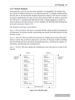
The architecture has a mesh of horizontal and vertical interconnect
tracks. At each junction, there is a fuse. With the aid of software
tools, the user can select which junctions will not be connected by
“blowing” all unwanted fuses. (This is done by a device programmer or
more commonly nowadays using In-System Programming or ISP).
Input pins are connected to the vertical interconnect and the horizontal
tracks are connected to AND-OR gates, also called “product terms”.
These in turn connect to dedicated flip-flops whose outputs are
connected to output pins.
PLDs provided as much as 50 times more gates in a single package
than discrete logic devices! A huge improvement, not to mention fewer
devices needed in inventory and higher reliability over standard logic.
Programmable Logic Device (PLD) technology has moved on from the
early days with such companies as Xilinx producing ultra low power
CMOS devices based on Flash technology. Flash PLDs provide the
Programmable Logic Design Quick Start Hand Book
© Xilinx
Page 13
Introduction
Chapter 1
ability to program the devices time and time again electrically
programming and ERASING the device! Gone are the days of erasing
taking in excess of twenty minutes under an UV eraser.
1.2
Complex Programmable Logic Devices (CPLDs)
Complex Programmable Logic Devices (CPLD) are another way to
extend the density of the simple PLDs. The concept is to have a few
PLD blocks or macrocells on a single device with general purpose
interconnect in between. Simple logic paths can be implemented
within a single block. More sophisticated logic will require multiple
blocks and use the general purpose interconnect in between to make
these connections.
Figure 1.3
CPLD Architecture
CPLDs are great at handling wide and complex gating at blistering
speeds e.g. 5ns which is equivalent to 200MHz. The timing model for
CPLDs is easy to calculate so before you even start your design you
can calculate your in to output speeds.
Programmable Logic Design Quick Start Hand Book
© Xilinx
Page 14
Introduction
1.2.1
Chapter 1
Why Use a CPLD?
CPLDs enable ease of design, lower development costs, more product
revenue for your money, and the opportunity to speed your products to
market...
Ease of Design: CPLDs offer the simplest way to implement design.
Once a design has been described, by schematic and/or HDL entry, a
designer simply uses CPLD development tools to optimise, fit, and
simulate the design. The development tools create a file, which is then
used to customise (program) a standard off-the-shelf CPLD with the
desired functionality. This provides an instant hardware prototype and
allows the debugging process to begin. If modifications are needed,
design changes are just entered into the CPLD development tool, and
the design can be re-implemented and tested immediately.
Lower Development Costs: CPLDs offer very low development costs.
Ease of design, as described above, allows for shorter development
cycles. Because CPLDs are re-programmable, designers can easily
and very inexpensively change their designs. This allows them to
optimise their designs and continues to add new features to continue
to enhance their products. CPLD development tools are relatively
inexpensive and in the case of Xilinx, are free. Traditionally, designers
have had to face large cost penalties such as re-work, scrap, and
development time. With CPLDs, designers have flexible solutions thus
avoiding many traditional design pitfalls.
More Product Revenue: CPLDs offer very short development cycles,
which means your products get to market quicker and begin
generating revenue sooner. Because CPLDs are re-programmable,
products can be easily modified using ISP over the Internet. This in
turn allows you to easily introduce additional features and quickly
generate new revenue from them. (This results in an expanded time
for revenue). Thousands of designers are already using CPLDs to
get to market quicker and then stay in the market longer by continuing
to enhance their products even after they have been introduced into the
field. CPLDs decrease Time To Market (TTM) and extend Time In
Market (TIM).
Programmable Logic Design Quick Start Hand Book
© Xilinx
Page 15
Introduction
Chapter 1
Reduced Board Area: CPLDs offer a high level of integration (large
number of system gates per area) and are available in very small
form factor packages. This provides the perfect solution for
designers of products which must fit into small enclosures or who
have a limited amount of circuit board space to implement the logic
design. The CoolRunner® CPLDs are available in the latest chip scale
packages, e.g. CP56 which has a pin pitch of 0.5mm and is a mere
6mm by 6mm in size so are ideal for small, low power end products.
Cost of Ownership: Cost of Ownership can be defined as the
amount it costs to maintain, fix, or warranty a product. For instance,
if a design change requiring hardware rework must be made to a
few prototypes, the cost might be relatively small. However, as the
number of units that must be changed increases, the cost can
become enormous. Because CPLDs are re-programmable, requiring
no hardware rework, it costs much less to make changes to designs
implemented using them. Therefore cost of ownership is dramatically
reduced. And don't forget the ease or difficulty of design changes
can also affect opportunity costs. Engineers who are spending a lot
of time fixing old designs could be working on introducing new
products and features - ahead of the competition.
There are also costs associated with inventory and reliability. PLDs
can reduce inventory costs by replacing standard discrete logic
devices. Standard logic has a predefined function and in a typical
design lots of different types have to be purchased and stocked. If the
design is changed then there may be excess stock of superfluous
devices. This issue can be alleviated by using PLDs i.e. you only need
to stock one device and if your design changes you simply reprogram.
By utilising one device instead of many your board reliability will
increase by only picking and placing one device instead of many.
Reliability can also be increased by using the ultra low power
CoolRunner CPLDs i.e. lower heat dissipation and lower power
operation leads to decreased Failures In Time (FIT).
Programmable Logic Design Quick Start Hand Book
© Xilinx
Page 16
Introduction
1.3
Chapter 1
Field Programmable Gate Arrays (FPGAs)
In 1985, a company called Xilinx introduced a completely new idea.
The concept was to combine the user control and time to market of
PLDs with the densities and cost benefits of gate arrays. A lot of
customers liked it - and the FPGA was born. Today Xilinx is still the
number one FPGA vendor in the world!
An FPGA is a regular structure of logic cells™ or modules and
interconnect which is under the designer’s complete control. This
means the user can design, program and make changes to his circuit
whenever he wants. And with FPGAs now exceeding the 10 million
gate limit (Xilinx Virtex® II is the current record holder), the designer
can dream big!
Figure 1.4
FPGA Architecture
With the introduction of the Spartan® range of FPGAs we can now
compete with Gate Arrays on all aspects - price, gate and I/O count,
Programmable Logic Design Quick Start Hand Book
© Xilinx
Page 17
Introduction
Chapter 1
performance and cost! The new Spartan IIE will provide up to 300k
gates at a price point that enables Application Specific Standard
Product (ASSP) replacement. For example a Reed Solomon IP Core
implemented in a Spartan II XC2S100 FPGA has an effective cost of
$9.95 whereas the equivalent ASSP would cost around $20.
There are 2 basic types of FPGAs: SRAM-based reprogrammable and
One-time programmable (OTP). These two types of FPGAs differ in
the implementation of the logic cell™ and the mechanism used to
make connections in the device.
The dominant type of FPGA is SRAM-based and can be
reprogrammed by the user as often as the user chooses. In fact, an
SRAM FPGA is reprogrammed every time it is powered-up because
the FPGA is really a fancy memory chip! (That’s why you need a
serial PROM or system memory with every SRAM FPGA).
Figure 1.5
Digital Logic History
Programmable Logic Design Quick Start Hand Book
© Xilinx
Page 18
Introduction
Chapter 1
In the SRAM logic cell, instead of conventional gates there is instead a
Look Up Table (LUT) which determines the output based on the values
of the inputs. (In the “SRAM logic cell” diagram above you can see 6
different combinations of the 4 inputs that will determine the values of
the output). SRAM bits are also used to make connections.
One-time programmable (OTP) FPGAs use anti-fuses (contrary to
fuses, connections are made not “blown” during programming) to make
permanent connections in the chip and so do not require a SPROM or
other means to download the program to the FPGA. However, every
time you make a design change, you must throw away the chip! The
OTP logic cell is very similar to PLDs with dedicated gates and flipflops.
Design Integration
The integration of 74 series standard logic into a low cost CPLD is a
very attractive proposition. Not only do you save Printed Circuit Board
(PCB) area and board layers therefore reducing your total system cost
but you only have to purchase and stock one generic part instead of
upto as many as twenty pre-defined logic devices. In production the
pick and place machine only has to place one part - therefore
speeding up production. Less parts means higher quality and better
Failure In Time (FIT) factor.
By using Xilinx CoolRunner devices (our family of ultra low power parts)
in a design customers can benefit from low power consumption and
reduced thermal emissions. This in turn leads to the reduction of the
use of heat sinks (another cost saving) and a higher reliability end
product.
Programmable Logic Design Quick Start Hand Book
© Xilinx
Page 19
Introduction
Figure 1.6
1.4
Chapter 1
Basic Logic Definitions
The Basic Design Process
The availability of design software such as WebPACK™ ISE has made
it much easier to design with programmable logic. Designs can be
described easily and quickly using either a description language such
as ABEL (Advanced Boolean Expression Language), VHDL (VHSIC
Hardware Description Language), Verilog or via a schematic capture
package.
Schematic capture is the traditional method that designers have used
to specify gate arrays and programmable logic devices. It is a
graphical tool that allows the designer to specify the exact gates he
requires and how he wants them connected. There are 4 basic steps
to using schematic capture.
Programmable Logic Design Quick Start Hand Book
© Xilinx
Page 20
Introduction
Chapter 1
Step one: After selecting a specific schematic capture tool and device
library, the designer begins building his circuit by loading the desired
gates from the selected library. He can use any combination of gates
that he needs. A specific vendor and device family library must be
chosen at this time (e.g. Xilinx XCR3256XL) but he doesn’t have to
know what device within that family he will ultimately use with respect
to package and speed.
Step two: Connect the gates together using nets or wires. The
designer has complete control of connecting the gates in whatever
configuration is required for his application.
Step three: The input and output buffers are added and labelled.
These will define the I/O package pins for the device.
Step four: The final step is to generate a netlist.
Figure 1.7
PLD Design Flow
Programmable Logic Design Quick Start Hand Book
© Xilinx
Page 21
Introduction
Chapter 1
The netlist is a text equivalent of the circuit which is generated by
design tools such as a schematic capture program. The netlist is a
compact way for other programs to understand what gates are in the
circuit, how they are connected and the names of the I/O pins.
In the example below, the netlist reflects the actual syntax for the
circuit in the schematic. There is one line for each of the components
and one line for each of the nets. Note that the computer assigns
names to components (G1 to G4) and the nets (N1 to N8). When we
implement this design, it will have input package pins A, B, C, D and
output pins Q, R, S.
EDIF (Electronic Digital Interchange Format) is the industry-wide
standard for netlists although there are many other including vendorspecific ones such as the Xilinx Netlist Format (XNF).
If you have the design netlist, you have all you need to determine what
the circuit does.
Figure 1.8
Design Specification - Netlist
Programmable Logic Design Quick Start Hand Book
© Xilinx
Page 22
Introduction
Chapter 1
The example on the previous pages are obviously very simplistic. A
more realistic design of 10,000 equivalent gates is shown here.
The typical schematic page contains about 200 gates included the
logic contained with soft macros. Therefore, it would require 50
schematic pages to create a 10,000 gate design! Each page needs to
go through all the steps mentioned previously: adding components,
interconnecting the gates, adding I/Os and generating a netlist! This is
rather time-consuming, especially if you want to design a 20k, 50k or
larger design.
Another inherent problem with using schematic capture is the difficulty
in migrating between vendors and technologies. If you initially create
your 10,000 gate design with FPGA vendor X and then want to migrate
to a gate array, you would have to modify every one of those 50 pages
using the gate array vendor’s component library! There has to be a
better way...
And of course, there is. It’s called High Level Design (HLD),
Behavioural or Hardware Description Language (HDL). For our
purposes, these three terms are essentially the same thing.
The idea is to use a high-level language to describe the circuit in a text
file rather than a graphical low-level gate description. The term
Behavioural is used because in this powerful language, the designer
describes the function or behaviour of the circuit in words rather than
figuring out the appropriate gates needed to create the application.
There are two major flavours of HDL: VHDL and Verilog. Although it’s
not really important for you to know, VHDL is an acronym for “VHSIC
High-level Design Language”. And yes, VHSIC is another acronym
“Very High Speed Integrated Circuit”.
As an example we will design a 16 by 16 multiplier specified with a
schematic and with an HDL file. A multiplier is a regular but complex
arrangement of adders and registers which requires quite a few gates.
Our example has two 16 bit inputs (A and B) and a 32 bit product
Programmable Logic Design Quick Start Hand Book
© Xilinx
Page 23
Introduction
Chapter 1
output (Y=A*B) - that’s a total of 64 I/Os. This circuit requires
approximately 6,000 equivalent gates.
In the schematic implementation, all the required gates would have to
be loaded, positioned on the page, interconnected, and I/O buffers
added. About 3 days worth of work.
The HDL implementation, which is also 6,000 gates, requires 8 lines of
text and can be done in 3 minutes. This file contains all the
information necessary to define our 16x16 multiplier!
So, as a designer, which method would you choose? In addition to
the tremendous time savings, the HDL method is completely vendorindependent. That means that this same code could be used to
implement a Xilinx FPGA as an LSI Logic gate array! This opens up
tremendous design possibilities for engineers. For example, what if
you wanted to create a 32X32 multiplier
Figure 1.9
Design Specification – Multiplier
Programmable Logic Design Quick Start Hand Book
© Xilinx
Page 24
Introduction
Chapter 1
Obviously, you would want to modify the work already done for the
smaller multiplier. For the schematic approach, this would entail
making 3 copies of the 30 pages, then figuring out where to edit the 90
pages so that they addressed the larger bus widths. This would
probably require 4 hours of graphical editing. For the HDL
specification, it would be a matter of changing the bus references:
change 15 to 31 in line 2 and 31 to 63 in line 3 (4 seconds)!
HDL File Change Example
Before (16x 16 multiplier):
entity MULT is
port(A,B:in std_logic(15 downto 0);
Y:out std_logic(31 downto 0));
end MULT;
architecture BEHAVE of MULT is
begin
Y <= A * B;
end BEHAVE;
After (32 x 32 multiplier):
entity MULT is
port(A,B:in std_logic(31 downto 0);
Y:out std_logic(63 downto 0));
end MULT;
architecture BEHAVE of MULT is
begin
Y <= A * B;
end BEHAVE;
Programmable Logic Design Quick Start Hand Book
© Xilinx
Page 25