BRC hệ THỐNG điều KHIỂN THẮNG NISSAN ALTIMA
Bạn đang xem bản rút gọn của tài liệu. Xem và tải ngay bản đầy đủ của tài liệu tại đây (2.13 MB, 92 trang )
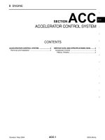
BRC-1
BRAKE CONTROL SYSTEM
F BRAKES
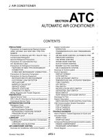
CONTENTS
C
D
E
G
H
I
J
K
L
M
SECTION
A
B
BRC
Revision: May 2004 2003 Altima
ABS
PRECAUTIONS 3
Precautions for Supplemental Restraint System
(SRS) “AIR BAG” and “SEAT BELT PRE-TEN-
SIONER” 3
Precautions for Brake System 3
Wiring Diagrams and Trouble Diagnosis 3
PREPARATION 4
Special Service Tool 4
Commercial Service Tools 4
GENERAL INFORMATION 5
Description 5
PURPOSE 5
OPERATION 5
Fail Safe 5
Hydraulic Circuit 5
System Components 6
Control Unit 6
ABS Actuator and Electric Unit (Control Unit) 6
ABS ACTUATOR OPERATION 6
Wheel Sensors 7
TROUBLE DIAGNOSIS 8
How to Perform Trouble Diagnoses for Quick and
Accurate Repair 8
INTRODUCTION 8
WORK FLOW 9
ASKING COMPLAINTS 10
EXAMPLE OF DIAGNOSIS SHEET 10
Component Parts and Harness Connector Location 11
Schematic 12
Wiring Diagram — ABS — 13
CONSULT–II Function 16
CONSULT-II APPLICATION TO ABS 16
SELF-DIAGNOSIS PROCEDURE 16
SELF-DIAGNOSTIC RESULTS MODE 18
DATA MONITOR PROCEDURE 19
DATA MONITOR MODE 20
ACTIVE TEST PROCEDURE 20
ACTIVE TEST MODE 21
Self-Diagnosis (Without CONSULT–II) 21
SELF-DIAGNOSIS PROCEDURE 22
HOW TO READ SELF-DIAGNOSTIC RESULTS
(MALFUNCTION CODES) 22
HOW TO ERASE SELF-DIAGNOSTIC
RESULTS (MALFUNCTION CODES) 23
Preliminary Check 23
Ground Circuit Check 25
ABS ACTUATOR AND ELECTRIC UNIT (CON-
TROL UNIT) GROUND 25
Malfunction Code Chart (Without CONSULT-II) 25
Symptom Chart 25
TROUBLE DIAGNOSIS FOR SELF-DIAGNOSTIC
ITEMS 27
Wheel Sensor or Rotor 27
DIAGNOSTIC PROCEDURE 27
ABS Actuator Solenoid Valve or Solenoid Valve
Relay 29
DIAGNOSTIC PROCEDURE 29
Motor Relay or Motor 32
DIAGNOSTIC PROCEDURE 32
Abnormal Battery Voltage 33
DIAGNOSTIC PROCEDURE 33
Controller Failure 35
DIAGNOSTIC PROCEDURE 35
TROUBLE DIAGNOSES FOR SYMPTOMS 36
1. ABS Works Frequently 36
2. Unexpected Pedal Action 36
3. Long Stopping Distance 37
4. ABS Does Not Work 37
5. Pedal Vibration and Noise 38
6. ABS Warning Lamp Does Not Come On When
Ignition Switch Is Turned On 39
7. ABS Warning Lamp Stays On When Ignition
Switch Is Turned On 41
WHEEL SENSORS 42
Removal and Installation 42
SENSOR ROTOR 43
Removal and Installation 43
REMOVAL 43
INSTALLATION 43
BRC-2
Revision: May 2004 2003 Altima
ACTUATOR AND ELECTRIC UNIT (ASSEMBLY) 44
Removal and Installation 44
REMOVAL 44
INSTALLATION 44
TCS/ABS
PRECAUTIONS 45
Precautions for Supplemental Restraint System
(SRS) “AIR BAG” and “SEAT BELT PRE-TEN-
SIONER” 45
Precautions for Brake System 45
Wiring Diagrams and Trouble Diagnosis 45
PREPARATION 46
Special Service Tool 46
Commercial Service Tools 46
GENERAL INFORMATION 47
Description 47
PURPOSE 47
ABS (ANTI-LOCK BRAKE SYSTEM) OPERA-
TION 47
TCS (TRACTION CONTROL SYSTEM) OPER-
ATION 47
Fail Safe 47
Hydraulic Circuit 48
System Components 48
Control Unit 49
ABS FUNCTION 49
TCS FUNCTION 49
ABS Actuator and Electric Unit 49
ABS ACTUATOR OPERATION 49
Wheel Sensors 49
CAN Communication System Description 50
FOR TCS MODELS 50
TROUBLE DIAGNOSIS 52
How to Perform Trouble Diagnoses for Quick and
Accurate Repair 52
INTRODUCTION 52
WORK FLOW 53
ASKING COMPLAINTS 54
EXAMPLE OF DIAGNOSIS SHEET 54
Component Parts and Harness Connector Location 55
Schematic 56
Wiring Diagram — TCS — 57
CONSULT–II Function 60
CONSULT-II APPLICATION TO ABS/TCS 60
SELF-DIAGNOSIS PROCEDURE 60
SELF-DIAGNOSTIC RESULTS MODE 62
DATA MONITOR PROCEDURE 63
DATA MONITOR MODE 64
ACTIVE TEST PROCEDURE 65
ACTIVE TEST MODE 66
Self-Diagnosis (Without CONSULT–II) 66
FUNCTION 66
SELF-DIAGNOSIS PROCEDURE 66
HOW TO READ SELF-DIAGNOSTIC RESULTS
(MALFUNCTION CODES) 67
HOW TO ERASE SELF-DIAGNOSTIC
RESULTS (MALFUNCTION CODES) 68
Preliminary Check 68
Ground Circuit Check 70
ABS ACTUATOR AND ELECTRIC UNIT (CON-
TROL UNIT) GROUND 70
ABS WARNING LAMP, TCS OFF INDICATOR
LAMP, SLIP INDICATOR LAMP ON/OFF TIMING 70
Malfunction Code Chart (Without CONSULT-II) 70
Symptom Chart 71
TROUBLE DIAGNOSIS FOR SELF-DIAGNOSTIC
ITEMS 73
CAN Communication Line or ABS Actuator and
Electric Unit (Control Unit) 73
DIAGNOSTIC PROCEDURE 73
Wheel Sensor or Rotor 73
DIAGNOSTIC PROCEDURE 73
ABS Actuator Solenoid Valve or Solenoid Valve
Relay 76
DIAGNOSTIC PROCEDURE 76
Motor Relay or Motor 79
DIAGNOSTIC PROCEDURE 79
Abnormal Battery Voltage 80
DIAGNOSTIC PROCEDURE 80
Controller Failure 82
DIAGNOSTIC PROCEDURE 82
TROUBLE DIAGNOSES FOR SYMPTOMS 83
1. ABS Works Frequently 83
2. Unexpected Pedal Action 83
3. Long Stopping Distance 84
4. ABS Does Not Work 84
5. Pedal Vibration and Noise 85
6. ABS Warning Lamp Does Not Come On When
Ignition Switch Is Turned On 86
7. ABS Warning Lamp Stays On When Ignition
Switch Is Turned On 88
8. During ABS/TCS Control, Vehicle Behavior is
Jerky. 88
WHEEL SENSORS 90
Removal and Installation 90
SENSOR ROTOR 91
Removal and Installation 91
REMOVAL 91
INSTALLATION 91
ACTUATOR AND ELECTRIC UNIT (ASSEMBLY) 92
Removal and Installation 92
REMOVAL 92
INSTALLATION 92
PRECAUTIONS
BRC-3
[ABS]
C
D
E
G
H
I
J
K
L
M
A
B
BRC
Revision: May 2004 2003 Altima
PRECAUTIONS PFP:00001
Precautions for Supplemental Restraint System (SRS) “AIR BAG” and “SEAT
BELT PRE-TENSIONER”
EFS0037E
The Supplemental Restraint System such as “AIR BAG” and “SEAT BELT PRE-TENSIONER”, used along
with a front seat belt, helps to reduce the risk or severity of injury to the driver and front passenger for certain
types of collision. This system includes seat belt switch inputs and dual stage front air bag modules. The SRS
system uses the seat belt switches to determine the front air bag deployment, and may only deploy one front
air bag, depending on the severity of a collision and whether the front occupants are belted or unbelted.
Information necessary to service the system safely is included in the SRS and SB section of this Service Man-
ual.
WARNING:
● To avoid rendering the SRS inoperative, which could increase the risk of personal injury or death
in the event of a collision which would result in air bag inflation, all maintenance must be per-
formed by an authorized NISSAN/INFINITI dealer.
● Improper maintenance, including incorrect removal and installation of the SRS, can lead to per-
sonal injury caused by unintentional activation of the system. For removal of Spiral Cable and Air
Bag Module, see the SRS section.
● Do not use electrical test equipment on any circuit related to the SRS unless instructed to in this
Service Manual. SRS wiring harnesses can be identified by yellow and/or orange harnesses or
harness connectors.
Precautions for Brake System
EFS0026A
CAUTION:
● Recommended fluid is brake fluid “DOT 3”.
● Never reuse drained brake fluid.
● Be careful not to splash brake fluid on painted areas; it may cause paint damage. If brake fluid is
splashed on painted areas, wash it away with water immediately.
● To clean or wash all parts of master cylinder and disc brake caliper, use clean brake fluid.
● Never use mineral oils such as gasoline or kerosene. They will ruin rubber parts of the hydraulic
system.
● Use flare nut wrench when removing and installing brake
tube.
● If a brake fluid leak is found, the part must be disassembled
without fail. Then it has to be replaced with a new one if a
defect exists.
● Turn the ignition switch OFF and remove the connector of
the ABS actuator control unit or the battery terminal before
performing the work.
● Always torque brake lines when installing.
● Burnish the brake contact surfaces after refinishing or
replacing rotors, after replacing pads, or if a soft pedal
occurs at very low mileage.
Refer to BR-23, "
Brake Burnishing Procedure"
WARNING:
● Clean brake pads and shoes with a waste cloth, then wipe with a dust collector.
Wiring Diagrams and Trouble Diagnosis
EFS0026B
When you read wiring diagrams, refer to the following:
● GI-12, "How to Read Wiring Diagrams"
● PG-3, "POWER SUPPLY ROUTING CIRCUIT"
When you perform trouble diagnosis, refer to the following:
● GI-10, "HOW TO FOLLOW TEST GROUPS IN TROUBLE DIAGNOSES"
● GI-25, "How to Perform Efficient Diagnosis for an Electrical Incident"
SBR686C
BRC-4
[ABS]
PREPARATION
Revision: May 2004 2003 Altima
PREPARATION PFP:00002
Special Service Tool
EFS0037F
The actual shapes of Kent-Moore tools may differ from those of special service tools illustrated here.
Commercial Service Tools
EFS0037G
Tool number
(Kent-Moore No.)
Tool name
Description
(J-45741)
ABS active wheel sensor tester
Checking operation of ABS active wheel
sensor
WFIA0101E
Tool name Description
1. Flare nut crowfoot
a: 10mm (0.39 in)/12mm (0.47 in)
2. Torque wrench
Removing and installing brake piping
S-NT360
GENERAL INFORMATION
BRC-5
[ABS]
C
D
E
G
H
I
J
K
L
M
A
B
BRC
Revision: May 2004 2003 Altima
GENERAL INFORMATION PFP:00000
Description
EFS0026C
PURPOSE
The ABS consists of electronic and hydraulic components. It allows for control of braking force so that locking
of the wheels can be avoided.
The ABS:
● Ensures proper tracking performance through steering wheel operation.
● Enables obstacles to be avoided through steering wheel operation.
● Ensures vehicle stability by preventing flat spins.
OPERATION
● When the vehicle speed is less than 10 km/h (6 MPH) this system does not work.
● The Anti-lock Brake System (ABS) has self-test capabilities. The system turns on the ABS warning lamp
for 1 second after turning the ignition switch ON. The system performs another test the first time the vehi-
cle reaches 6 km/h (4 MPH). A mechanical noise may be heard as the ABS performs a self-test. This is a
normal part of the self-test feature. If a malfunction is found during this check, the ABS warning lamp will
come on.
● During ABS operation, a mechanical noise may be heard. This is a normal condition.
Fail Safe
EFS0026D
If trouble occurs in the ABS, the ABS warning lamp in the combination meter comes on. At the same time, the
vehicle stops the ABS control and braking becomes the same as that of a vehicle without ABS.
Hydraulic Circuit
EFS0026E
1. Inlet solenoid valve 4. Pump 7. Outlet valve
2. Outlet solenoid valve 5. Motor 8. Bypass check valve
3. Reservoir 6. Inlet valve 9. Damper
SBR984D
BRC-6
[ABS]
GENERAL INFORMATION
Revision: May 2004 2003 Altima
System Components
EFS0026F
Control Unit
EFS0026G
The control unit computes the wheel rotating speed by the signal
sent from the sensor. Then it supplies a DC current to the actuator
solenoid valve. It also controls ON-OFF operation of the valve relay
and motor relay. If any electrical malfunction should be detected in
the system, the control unit causes the warning lamp to light up. In
this condition, the ABS will be deactivated by the control unit, and
the vehicle's brake system reverts to normal operation.
ABS Actuator and Electric Unit (Control Unit)
EFS0026H
The ABS actuator and electric unit (control unit) contains:
● An electric motor and pump
● Two relays
● Eight solenoid valves, each inlet and outlet for
— LH front
— RH front
— LH rear
— RH rear
● ABS control unit
This components controls the hydraulic circuit and increases, holds or decreases hydraulic pressure to all or
individual wheels. The ABS actuator and electric unit (control unit) cannot be disassembled and must be
replaced as an assembly.
ABS ACTUATOR OPERATION
LFIA0087E
LFIA0099E
Inlet solenoid
valve
Outlet solenoid
valve
Normal brake operation OFF (Open) OFF (Closed)
Master cylinder brake fluid pressure is directly trans-
mitted to caliper via the inlet solenoid valve.
GENERAL INFORMATION
BRC-7
[ABS]
C
D
E
G
H
I
J
K
L
M
A
B
BRC
Revision: May 2004 2003 Altima
Wheel Sensors
EFS0026I
The front sensor units consist of a gear-shaped sensor rotor and a
sensor element. the element contains a magnet around which a coil
is wound. The front wheel sensors are installed on the front of the
wheel knuckles. As the wheel rotates, the sensor generates a
square-wave signal. The frequency increases as the wheel speed
increases.
The rear sensor units consist of wheel hubs with a series of internal
magnets and a sensor element. The rear wheel sensors are
installed on the inner side of the wheel knuckles. As the wheel
rotates, the sensor generates a square-wave signal. The frequency
increases as the wheel speed increases.
ABS operation
Pressure hold ON (Closed) OFF (Closed)
Hydraulic circuit is shut off to hold the caliper brake
fluid pressure.
Pressure
decrease
ON (Closed) ON (Open)
Caliper brake fluid is sent to reservoir via the outlet
solenoid valve. Then it is pushed up to the master cyl-
inder by pump.
Pressure
increase
OFF (Open) OFF (Closed)
Master cylinder brake fluid pressure is transmitted to
caliper.
LBR333
WFIA0033E
BRC-8
[ABS]
TROUBLE DIAGNOSIS
Revision: May 2004 2003 Altima
TROUBLE DIAGNOSIS PFP:00000
How to Perform Trouble Diagnoses for Quick and Accurate Repair
EFS0026J
INTRODUCTION
The ABS system has an electronic control unit to control major func-
tions. The control unit accepts input signals from sensors and con-
trols operation of the actuator. It is also important to check for
conventional problems such as air leaks in the booster or lines, lack
of brake fluid, or other problems with the brake system.
It is much more difficult to diagnose a problem that occurs intermit-
tently rather than continuously. Most intermittent problems are
caused by poor electrical connections or faulty wiring. In this case,
careful checking of suspicious circuits may help prevent the replace-
ment of good parts.
A visual check only may not find the cause of the problem, so a road
test should be performed.
Before undertaking actual checks, take just a few minutes to talk with
a customer who approaches with an ABS complaint. The customer
is a very good source of information on such problems, especially
intermittent ones. Through the talks with the customer, find out what
symptoms are present and under what conditions they occur.
Start your diagnosis by looking for “conventional” problems first. This
is one of the best ways to troubleshoot brake problems on an ABS
controlled vehicle. Also check related Service Bulletins for informa-
tion.
SEF233G
SEF234G
TROUBLE DIAGNOSIS
BRC-9
[ABS]
C
D
E
G
H
I
J
K
L
M
A
B
BRC
Revision: May 2004 2003 Altima
WORK FLOW
LFIA0197E
BRC-10
[ABS]
TROUBLE DIAGNOSIS
Revision: May 2004 2003 Altima
ASKING COMPLAINTS
● Complaints against a malfunction vary depending on each per-
son. It is important to clarify the customer complaints.
● Ask the customer about what symptoms are present under what
conditions. Use the information to reproduce the symptom while
driving.
● It is also important to use the diagnosis sheet to understand
what type of trouble the customer is having.
EXAMPLE OF DIAGNOSIS SHEET
SBR339B
LFIA0198E
TROUBLE DIAGNOSIS
BRC-11
[ABS]
C
D
E
G
H
I
J
K
L
M
A
B
BRC
Revision: May 2004 2003 Altima
Component Parts and Harness Connector Location
EFS0026K
LFIA0201E
BRC-12
[ABS]
TROUBLE DIAGNOSIS
Revision: May 2004 2003 Altima
Schematic
EFS0026L
LFWA0009E
TROUBLE DIAGNOSIS
BRC-13
[ABS]
C
D
E
G
H
I
J
K
L
M
A
B
BRC
Revision: May 2004 2003 Altima
Wiring Diagram — ABS —
EFS0026M
LFWA0010E
BRC-14
[ABS]
TROUBLE DIAGNOSIS
Revision: May 2004 2003 Altima
LFWA0011E
TROUBLE DIAGNOSIS
BRC-15
[ABS]
C
D
E
G
H
I
J
K
L
M
A
B
BRC
Revision: May 2004 2003 Altima
LFWA0012E
BRC-16
[ABS]
TROUBLE DIAGNOSIS
Revision: May 2004 2003 Altima
CONSULT–II Function
EFS0026N
CONSULT-II APPLICATION TO ABS
X: Applicable
—: Not applicable
ECU (ABS Control Unit) Part Number Mode
Ignore the ECU part number displayed in the ECU PART NUMBER MODE. Refer to parts catalog to order the
ABS actuator and electric unit (control unit).
SELF-DIAGNOSIS PROCEDURE
1. Turn ignition switch OFF.
2. Connect CONSULT-II to data link connector.
3. Start engine.
4. Drive vehicle over 30 km/h (19 MPH) for at least one minute.
ITEM
SELF-DIAGNOSTIC
RESULTS
DATA MONITOR ACTIVE TEST
Front right wheel sensor X X —
Front left wheel sensor X X —
Rear right wheel sensor X X —
Rear left wheel sensor X X —
Stop lamp switch — X —
Front right inlet solenoid valve X X X
Front right outlet solenoid valve X X X
Front left inlet solenoid valve X X X
Front left outlet solenoid valve X X X
Rear right inlet solenoid valve X X X
Rear right outlet solenoid valve X X X
Rear left inlet solenoid valve X X X
Rear left outlet solenoid valve X X X
Actuator solenoid valve relay X X —
Actuator motor relay X X X
ABS warning lamp — X —
Battery voltage X X —
Control unit X ——
BBIA0002E
TROUBLE DIAGNOSIS
BRC-17
[ABS]
C
D
E
G
H
I
J
K
L
M
A
B
BRC
Revision: May 2004 2003 Altima
5. Stop vehicle with engine running and touch “START” on CON-
SULT-II screen.
6. Touch “ABS”.
7. Touch “SELF-DIAG RESULTS”.
● The screen shows the detected malfunction and how many
times the ignition switch has been turned since the malfunc-
tion.
8. Make the necessary repairs following the diagnostic procedures.
9. After the malfunctions are repaired, erase the self-diagnostic
results stored in the control unit by touching “ERASE”.
10. Check ABS warning lamp for deactivation after driving vehicle
over 30 km/h (19 MPH) for at least one minute.
NOTE:
“SELF-DIAG RESULTS” screen shows the detected malfunction and
how many times the ignition switch has been turned since the mal-
function.
PBR455D
PBR385C
WFIA0043E
WFIA0044E
BRC-18
[ABS]
TROUBLE DIAGNOSIS
Revision: May 2004 2003 Altima
SELF-DIAGNOSTIC RESULTS MODE
*1: Be sure to confirm the ABS warning lamp illuminates when the ignition switch is turned ON after repairing the shorted sensor circuit,
but the lamp goes out when driving the vehicle over 30 km/h (19 MPH) for one minute in accordance with SELF-DIAGNOSIS PROCE-
DURE.
*2: When “CONTROLLER FAILURE” is displayed, check to see if the ABS warning lamp is burned out, and check the circuit between
the ABS warning lamp and ABS actuator and electric unit (control unit) for open or short. Then check the ABS actuator and electric unit
(control unit) and circuit.
Diagnostic item Diagnosed condition Diagnostic item is detected when
Reference
Page
FR RH SENSOR-1
[C1103]*1
Open
● Circuit for front right wheel sensor is open.
BRC-27
FR LH SENSOR-1
[C1104]*1
Open
● Circuit for front left wheel sensor is open.
RR RH SENSOR-1
[C1101]*1
Open
● Circuit for rear right wheel sensor is open.
RR LH SENSOR-1
[C1102]*1
Open ● Circuit for rear left wheel sensor is open.
FR RH SENSOR-2
[C1107]*1
Short
● Circuit for front right wheel sensor is shorted.
FR LH SENSOR-2
[C1108]*1
Short
● Circuit for front left wheel sensor is shorted.
RR RH SENSOR-2
[C1105]*1
Short ● Circuit for rear right wheel sensor is shorted.
RR LH SENSOR-2
[C1106]*1
Short
● Circuit for rear left wheel sensor is shorted.
ABS SENSOR
[C1115]
Abnormal signal
● Teeth damage on sensor rotor or improper installation of
wheel sensor.
FR RH IN ABS SOL
[C1122]
Abnormal
(Open, Short)
● Circuit for front right inlet solenoid valve is open or shorted.
(An excessively high or low output voltage is entered.)
BRC-29
FR LH IN ABS SOL
[C1120]
Abnormal
(Open, Short)
● Circuit for front left inlet solenoid valve is open or shorted.
(An excessively high or low output voltage is entered.)
FR RH OUT ABS SOL
[C1123]
Abnormal
(Open, Short)
● Circuit for front right outlet solenoid valve is open or shorted.
(An excessively high or low output voltage is entered.)
FR LH OUT ABS SOL
[C1121]
Abnormal
(Open, Short)
● Circuit for front left outlet solenoid valve is open or shorted.
(An excessively high or low output voltage is entered.)
RR RH IN ABS SOL
[C1126]
Abnormal
(Open, Short)
● Circuit for rear right inlet solenoid valve is open or shorted.
(An excessively high or low output voltage is entered.)
RR LH IN ABS SOL
[C1124]
Abnormal
(Open, Short)
● Circuit for rear left inlet solenoid valve is open or shorted.
(An excessively high or low output voltage is entered.)
RR RH OUT ABS SOL
[C1127]
Abnormal
(Open, Short)
● Circuit for rear right outlet solenoid valve is open or shorted.
(An excessively high or low output voltage is entered.)
RR LH OUT ABS SOL
[C1125]
Abnormal
(Open, Short)
● Circuit for rear left outlet solenoid valve is open or shorted.
(An excessively high or low output voltage is entered.)
MAIN RELAY
[C1114]
Abnormal
● Actuator solenoid valve relay is ON, even if control unit sends
off signal.
● Actuator solenoid valve relay is OFF, even if control unit
sends on signal.
PUMP MOTOR
[C1111]
Abnormal
● Circuit for actuator motor is open or shorted.
● Actuator motor relay is stuck.
BRC-32
BATTERY VOLT
[ABNORMAL]
[C1109]
High or Low
● Power source voltage supplied to ABS control unit is abnor-
mally high or low.
BRC-33
CONTROLLER FAILURE*2
[C1110]
Control Unit
● Function of calculation in ABS control unit has malfunctioned. BRC-35
TROUBLE DIAGNOSIS
BRC-19
[ABS]
C
D
E
G
H
I
J
K
L
M
A
B
BRC
Revision: May 2004 2003 Altima
DATA MONITOR PROCEDURE
1. Turn ignition switch OFF.
2. Connect CONSULT-II to data link connector.
3. Turn ignition switch ON.
4. Touch “START” on CONSULT-II screen.
5. Touch “ABS”.
6. Touch “DATA MONITOR”.
7. Touch “SETTING” on “SELECT MONITOR ITEM” screen.
8. Touch “LONG TIME” on “SET RECORDING COND” screen.
9. Touch “START” on “SELECT MONITOR ITEM”.
BBIA0002E
PBR455D
PBR385C
WFIA0043E
BRC-20
[ABS]
TROUBLE DIAGNOSIS
Revision: May 2004 2003 Altima
DATA MONITOR MODE
ACTIVE TEST PROCEDURE
● When conducting active test, vehicle must be stationary.
● When ABS warning lamp stays on, never conduct active test.
1. Turn ignition switch OFF.
2. Connect CONSULT-II to data link connector.
3. Start engine.
4. Touch “START” on CONSULT-II screen.
MONITOR ITEM CONDITION SPECIFICATION
FR RH SENSOR
FR LH SENSOR
RR RH SENSOR
RR LH SENSOR
Drive vehicle.
(Each wheel is rotating.)
Displays computed vehicle speed from wheel sensor signal.
Almost the same speed as speedometer.
STOP LAMP SW
Turn ignition switch ON and
depress brake pedal.
Depress the pedal: ON
Release the pedal: OFF
FR RH IN SOL
FR RH OUT SOL
FR LH IN SOL
FR LH OUT SOL
RR RH IN SOL
RR RH OUT SOL
RR LH IN SOL
RR LH OUT SOL
Ignition switch is turned ON or
engine is running.
Operating conditions for each solenoid valve are indicated.
ABS is not operating: OFF
ACTUATOR RLY
Ignition switch is turned ON or
engine is running.
Displays ON/OFF condition of ABS actuator relay.
When turning ignition switch ON, ABS actuator relay is operated.
MOTOR RELAY
ABS is not operating: OFF
ABS is operating: ON
ABS WARN LAMP
Warning lamp is turned on: ON
Warning lamp is turned off: OFF
BATTERY VOLT Power supply voltage for control unit
BBIA0002E
PBR455D
TROUBLE DIAGNOSIS
BRC-21
[ABS]
C
D
E
G
H
I
J
K
L
M
A
B
BRC
Revision: May 2004 2003 Altima
5. Touch “ABS”.
6. Touch “ACTIVE TEST”.
7. Select active test item by touching screen.
8. Touch “START”.
9. Carry out the active test by touching screen key.
ACTIVE TEST MODE
NOTE:
Active test will automatically stop ten seconds after the test starts. (TEST IS STOPPED is displayed.)
Self-Diagnosis (Without CONSULT–II)
EFS0026O
When a problem occurs in the ABS, the ABS warning lamp on the instrument panel comes on. To activate the
self-diagnostic results mode, ground the self-diagnostic (check) terminal located on data link connector. The
location of the malfunction is indicated by the ABS warning lamp flashing.
PBR385C
WFIA0043E
WFIA0045E
TEST ITEM CONDITION JUDGEMENT
FR RH SOL
FR LH SOL
RR RH SOL
RR LH SOL
Ignition switch is turned ON.
Brake fluid pressure control operation
IN SOL OUT SOL
UP (Increase): OFF OFF
KEEP (Hold): ON OFF
DOWN (Decrease): ON ON
ABS MOTOR
ABS actuator motor
ON: Motor runs
OFF: Motor stops
BRC-22
[ABS]
TROUBLE DIAGNOSIS
Revision: May 2004 2003 Altima
SELF-DIAGNOSIS PROCEDURE
1. Drive vehicle over 30 km/h (19 MPH) for at least one minute.
2. Turn ignition switch OFF.
3. Ground terminal “9” of data link connector with a suitable har-
ness.
4. Turn ignition switch ON while grounding terminal “9”.
Do not depress brake pedal.
Do not start engine.
5. After 3.0 seconds, the ABS warning lamp starts flashing to indi-
cate the malfunction code No. (See NOTE.)
6. Verify the location of the malfunction with the malfunction code
chart. Refer to BRC-25, "
Malfunction Code Chart (Without CON-
SULT-II)" . Then make the necessary repairs following the diag-
nostic procedures.
7. After the malfunctions are repaired, erase the malfunction codes
stored in the control unit. Refer to BRC-23, "
HOW TO ERASE
SELF-DIAGNOSTIC RESULTS (MALFUNCTION CODES)" .
8. Rerun the self-diagnostic results mode to verify that the malfunc-
tion codes have been erased.
9. Disconnect the check terminal from the ground. The self-diagnostic results mode is now complete.
10. Check ABS warning lamp for deactivation after driving vehicle over 30 km/h (19 MPH) for at least one
minute.
11. After making certain that ABS warning lamp does not come on, test the ABS SELF-DIAGNOSIS in a safe
area to verify that it functions properly.
NOTE:
The indication terminates after five minutes.
However, when the ignition switch is turned from OFF to ON, the indication starts flashing again.
HOW TO READ SELF-DIAGNOSTIC RESULTS (MALFUNCTION CODES)
1. Determine the code No. by counting the number of times the ABS warning lamp flashes on and off.
2. When several malfunctions occur at one time, up to three code numbers can be stored; the latest mal-
function will be indicated first.
3. The indication begins with the start code 12. After that a maximum of three code numbers appear in the
order of the latest one first. The indication then returns to the start code 12 to repeat (the indication will
stay on for five minutes at the most).
4. Refer to BRC-25, "
Malfunction Code Chart (Without CONSULT-II)" .
BBIA0002E
LFIA0099E
SBR457D
TROUBLE DIAGNOSIS
BRC-23
[ABS]
C
D
E
G
H
I
J
K
L
M
A
B
BRC
Revision: May 2004 2003 Altima
HOW TO ERASE SELF-DIAGNOSTIC RESULTS (MALFUNCTION CODES)
1. Disconnect the check terminal from ground (ABS warning lamp
will stay lit).
2. Within 12.5 seconds, ground the check terminal 3 times. Each
terminal ground must last more than 1 second. The ABS warn-
ing lamp goes out after the erase operation has been com-
pleted.
3. Perform self-diagnosis again. Refer to BRC-22, "
SELF-DIAG-
NOSIS PROCEDURE" . Only the start code should appear, no
malfunction codes.
Preliminary Check
EFS0026P
1. CHECK BRAKE FLUID LEVEL
Low fluid level may indicate brake pad wear or leakage from brake
line.
Is brake fluid filled between MAX and MIN lines on reservoir tank
and is brake fluid uncontaminated?
OK >> GO TO 2.
NG >> Repair. GO TO 2.
2. CHECK BRAKE LINE
Is leakage present at or around brake lines, tubes or hoses or are
any of these parts cracked or damaged?
OK >> GO TO 3.
NG >> Repair. GO TO 3.
3. CHECK BRAKE BOOSTER OPERATION
Check brake booster for operation and air tightness.
Refer to BR-15, "
AIRTIGHT CHECK" .
Is brake booster airtight and functioning properly?
Yes >> GO TO 4.
No >> Replace. GO TO 4.
ABR256
SBR451D
SBR389C
SBR058C
BRC-24
[ABS]
TROUBLE DIAGNOSIS
Revision: May 2004 2003 Altima
4. CHECK BRAKE PADS AND ROTORS
Check brake pads and rotors.
Refer to BR-18, "
FRONT DISC BRAKE" and BR-24, "REAR DISC
BRAKE" .
Are brake pads and rotors functioning properly?
Yes >> GO TO 5.
No >> Replace.
5. RECHECK BRAKE FLUID LEVEL
Check brake fluid level in reservoir tank again.
Is brake fluid filled between MAX and MIN lines on reservoir tank
and is brake fluid uncontaminated?
OK >> GO TO 6.
NG >> Fill up brake fluid.
6. CHECK WARNING LAMP ACTIVATION
Does warning lamp turn on when ignition switch is turned ON?
Yes >> GO TO 7.
No >> Check fuse, warning lamp bulb and warning lamp circuit.
7. CHECK WARNING LAMP DEACTIVATION
Does warning lamp turn off when engine is started?
Yes >> GO TO 8.
No >> Go to Self-diagnosis. Refer to BRC-22, "
SELF-DIAGNOSIS PROCEDURE" .
8. DRIVE VEHICLE
Drive vehicle at speeds over 30 km/h (19 MPH) for at least one minute.
Does warning lamp remain off after vehicle has been driven at 30 km/h (19 MPH) for at least one minute?
Yes >> INSPECTION END.
No >> Go to Self-diagnosis. Refer to BRC-22, "
SELF-DIAGNOSIS PROCEDURE" .
SBR059C
SBR451D
LFIA0099E
TROUBLE DIAGNOSIS
BRC-25
[ABS]
C
D
E
G
H
I
J
K
L
M
A
B
BRC
Revision: May 2004 2003 Altima
Ground Circuit Check
EFS0026Q
ABS ACTUATOR AND ELECTRIC UNIT (CONTROL UNIT) GROUND
● Check continuity between terminals and ground.
Malfunction Code Chart (Without CONSULT-II)
EFS0026R
*: Under voltage that is too low, the control unit will disable the ABS. It does not set the ABS in fail-safe condition. Instead, the ABS
becomes a conventional brake system. After the power supply has resumed, the warning lamp goes off, making it possible for the ABS
to be re-engaged.
Symptom Chart
EFS0026S
Continuity should exist.
SFIA0296E
Code No. (No. of LED flashes) Malfunctioning part Reference page
12 Self-diagnosis could not detect any malfunctions. —
18 Sensor rotor malfunction BRC-27
21, 22 Front right sensor BRC-27
25, 26 Front left sensor BRC-27
31, 32 Rear right sensor BRC-27
35, 36 Rear left sensor BRC-27
41 Actuator front right outlet solenoid valve BRC-29
42 Actuator front right inlet solenoid valve BRC-29
45 Actuator front left outlet solenoid valve BRC-29
46 Actuator front left inlet solenoid valve BRC-29
51 Actuator rear right outlet solenoid valve BRC-29
52 Actuator rear right inlet solenoid valve BRC-29
55 Actuator rear left outlet solenoid valve BRC-29
56 Actuator rear left inlet solenoid valve BRC-29
57* Power supply (Abnormal voltage) BRC-33
61 Actuator motor or motor relay BRC-32
63 Solenoid valve relay BRC-29
71 Control unit BRC-35
Symptom Malfunctioning part Reference page
ABS warning lamp stays on when igni-
tion switch is turned on.
Control unit power supply circuit
Warning lamp bulb circuit
Control unit or control unit connector
Solenoid valve relay stuck
Power supply for solenoid valve relay coil
BRC-41
ABS warning lamp stays on, during
self-diagnosis.
Control unit —
ABS warning lamp does not come on
when ignition switch is turned on.
Fuse, warning lamp bulb or warning lamp circuit
Control unit
BRC-39
ABS warning lamp does not come on
during self-diagnosis.
Control unit —
Pedal vibration and noise — BRC-38