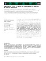
Application of the MC34063 switching regulator
Bạn đang xem bản rút gọn của tài liệu. Xem và tải ngay bản đầy đủ của tài liệu tại đây (169.26 KB, 14 trang )
ApplicationReport
SLVA252B–September2006–RevisedNovember2007
ApplicationoftheMC34063SwitchingRegulator
ShafiSekanderandMahmoudHarmouch SLLLinear
ABSTRACT
Thisapplicationreportprovidesthefeaturesthatarenecessarytoimplementdc-to-dc
fixed-frequencyschemeswithaminimumnumberofexternalcomponentsusingthe
MC34063.Thisdevicerepresentssignificantadvancementsineaseofusewithhighly
efficientand,yet,simpleswitchingregulators.Theuseofswitchingregulatoris
becomingmorepronouncedoverthatoflinearregulators,becauseofthesizeand
power-efficiencyrequirementofnewequipmentdesigns.Theuseofswitching
regulatorsincreasesapplicationflexibilityandreducesthecost.
Contents
1MC34063Description 2
2FunctionalDescription 5
3BuckRegulator 6
4BoostSwitchingRegulator 9
5InvertingSwitchingRegulator 11
6SelectingtheRightInductor 13
ListofFigures
1FunctionalBlockDiagram 2
2ReferenceVoltageCircuit 2
3OscillatorVoltageThresholds 3
4TimingCapacitorChargeCurrentvsCurrent-LimitSenseVoltage 3
5TypicalOperationWaveforms 4
6BuckRegulator 6
7BuckSwitchingRegulatorWaveforms 8
8BoostSwitchingRegulator 9
9BoostSwitchingRegulatorWaveforms 11
10SwitchingInverterRegulator 11
11InverterSwitchingRegulatorWaveforms 12
ListofTables
1LogicTruthTableofFunctionalBlocks 5
SLVA252B–September2006–RevisedNovember2007ApplicationoftheMC34063SwitchingRegulator1
SubmitDocumentationFeedback
www.ti.com
1MC34063Description
-
+
QS
1.25-V
Reference
Regulator
R
C
T
I
pk
Oscillator
Q2
Q1
Switch
Collector
4
Switch
Emitter
Timing
Capacitor
GND
3
2
18
7
6
5
Comparator
Inverting Input
V
CC
I
pk
Sense
Drive
Collector
100 W
Comparator
Latch
1.1ReferenceVoltage
Comparator
Inverting Input
Output
R2 R1
V = 1.25(R2/R1 + 1)
out
MC34063Description
TheMC34063isamonolithiccontrolcircuitcontainingalltheactivefunctionsrequiredforswitching
dc-to-dcconverters(seeFigure1).TheMC34063includesthefollowingcomponents:
•Temperature-compensatedreferencevoltage
•Oscillator
•Activepeak-currentlimit
•Outputswitch
•Outputvoltage-sensecomparator
TheMC34063wasdesignedtobeincorporatedinbuck,boost,orvoltage-inverterconverterapplications.
Allthesefunctionsarecontainedinan8-pinDIPorSOICpackage.
Figure1.FunctionalBlockDiagram
Thereferencevoltageissetat1.25Vandisusedtosettheoutputvoltageoftheconverter.
Figure2.ReferenceVoltageCircuit
ApplicationoftheMC34063SwitchingRegulator 2SLVA252B–September2006–RevisedNovember2007
SubmitDocumentationFeedback
www.ti.com
1.2Oscillator
Upper Threshold (1.25 V Typical)
Lower Threshold (0.75 V Typical)
Discharge
Time
V
Charge
6t
t
1.3CurrentLimit
V – Current-Limit Sense Voltage – V
CLS
I
– Charging Current – mA
chg
0 0.2 0.4 0.6 0.8
1
0.03
0.1
0.3
1
3
10
30
V = 5V
CC
T = 25°C
A
V = 40V
CC
I = I
chg dischg
MC34063Description
Theoscillatoriscomposedofacurrentsourceandacurrentsinkthatchargeanddischargetheexternal
timingcapacitor(C
T
)betweenanupperandlowerpresetthreshold.Thetypicalchargecurrentis35µA,
andthetypicaldischargecurrentis200µA,yieldingapproximatelya6:1ratio.Thus,theramp-upperiodis
sixtimeslongerthanthatoftheramp-downperiod(seeFigure3).
Theupperthresholdis1.25V,whichissameastheinternalreferencevoltage,andthelowerthresholdis
0.75V.Theoscillatorrunsconstantly,atapacecontrolledbythevalueofC
T
.
Figure3.OscillatorVoltageThresholds
Currentlimitisaccomplishedbymonitoringthevoltagedropacrossanexternalsenseresistorlocatedin
serieswithV
CC
andtheoutputswitch.Thevoltagedropdevelopedacrossthesenseresistorismonitored
bythecurrent-sensepin,I
pk
.Whenthevoltagedropacrossthesenseresistorbecomesgreaterthanthe
presetvalueof330mV,thecurrent-limitcircuitryprovidesanadditionalcurrentpathtochargethetiming
capacitor(C
T
)rapidly,toreachtheupperoscillatorthresholdand,thus,limitingtheamountofenergy
storedintheinductor.Theminimumsenseresistoris0.2Ω.Figure4showsthetimingcapacitorcharge
currentversuscurrent-limitsensevoltage.Tosetthepeakcurrent,I
pk
=330mV/R
sense
.
Figure4.TimingCapacitorChargeCurrentvsCurrent-LimitSenseVoltage
SLVA252B–September2006–RevisedNovember2007ApplicationoftheMC34063SwitchingRegulator3
SubmitDocumentationFeedback
www.ti.com
1.4OutputSwitch
Comparator Output
Timing Capacitor, C
T
Output Switch
Nominal Output Voltage
Output Voltage
1
0
On
Off
Startup Quiescent Operation
MC34063Description
TheoutputswitchisanNPNDarlingtontransistor.Thecollectoroftheoutputtransistoristiedtopin1,
andtheemitteristiedtopin2.ThisallowsthedesignertousetheMC34063inbuck,boost,orinverter
configurations.Themaximumcollector-emittersaturationvoltageat1.5A(peak)is1.3V,andthe
maximumpeakcurrentoftheoutputswitchis1.5A.Forhigherpeakoutputcurrent,anexternaltransistor
canbeused.Figure5showsthetypicaloperationwaveforms.
Figure5.TypicalOperationWaveforms
ApplicationoftheMC34063SwitchingRegulator 4SLVA252B–September2006–RevisedNovember2007
SubmitDocumentationFeedback
www.ti.com
2FunctionalDescription
FunctionalDescription
Theoscillatoriscomposedofacurrentsourceandsink,whichchargeanddischargetheexternaltiming
capacitor(C
T
)betweenanupperandlowerpresetthreshold.Thetypicalchargeanddischargecurrents
are35mAand200mA,respectively,yieldingapproximatelya6:1ratio.Thus,theramp-upperiodissix
timeslongerthanthatoftheramp-downperiod(seeFigure3).Theupperthresholdisequaltointernal
referencevoltageof1.25V,andthelowerthresholdisapproximatelyequalto0.75V.Theoscillatorruns
continuouslyataratecontrolledbythevalueofC
T
.
Duringtheramp-upportionofthecycle,alogic1ispresentattheAinputoftheANDgate.Iftheoutput
voltageoftheswitchingregulatorisbelownominal,alogic1isalsopresentattheBinput.Thiscondition
setsthelatchandcausestheQoutputtobealogic1,enablingthedriverandoutputswitchtoconduct.
Whentheoscillatorreachesitsupperthreshold,C
T
startstodischarge,andalogic0ispresentattheA
inputoftheANDgate.Thislogiclevelisalsoconnectedtoaninverterwhoseoutputpresentsalogic1to
theresetinputofthelatch.ThisconditioncausesQtogolow,disablingthedriverandoutputswitch.A
logictruthtableofthesefunctionalblocksisshowninTable1.
Table1.LogicTruthTableofFunctionalBlocks
ANDGateInputsLatchInputs
ActiveConditionofOutput
Comments
TimingCapacitor,C
T
Switch
ABSR
Regulatoroutputisgreaterthanor
Beginrampup000
equaltonominal(B=0).
Nochange,becauseBwas0before
Beginrampdown000
C
T
rampdown.
Nochangeeventhoughregulator
outputlessthannominal.Output
Rampingdown0010
switchcannotbeinitiatedduringR
T
rampdown.
Nochange,becauseoutputswitch
Rampingdown0010
conditionwasterminatedwhenA=0.
Regulatoroutputbecamelessthan
nominalduringC
T
rampup(whenB
Rampingup10
changedto1).Partialoncyclefor
outputswitch.
Regulatoroutputbecamegreaterthan
orequaltonominal(Bchangedto0)
Rampingup101
duringrampupofC
T
.Nochange,
becauseBcannotresetthelatch.
Completeoncycle,becauseB=1
Beginrampup1
beforeC
T
rampupstarted.
Outputswitchconductionisalways
Beginrampdown1
terminatedwhenC
T
isrampingdown.
TheoutputofthecomparatorcansetthelatchonlyduringtherampupofC
T
andcaninitiateapartialor
fulloncycleofoutputswitchconduction.Oncethecomparatorhassetthelatch,itcannotresetit.The
latchremainssetuntilC
T
beginsrampingdown.Thus,thecomparatorcaninitiateoutputswitch
conductionbutcannotterminateit,andthelatchisalwaysresetwhenC
T
beginsrampingdown.The
comparator’soutputisatalogic0whentheoutputvoltageoftheswitchingregulatorisabovenominal.
Undertheseconditions,thecomparator’soutputcaninhibitaportionoftheoutputswitchoncycle,a
completecycle,acompletecycleplusaportionofonecycle,multiplecycle,ormultiplecyclesplusa
portionofonecycle.
SLVA252B–September2006–RevisedNovember2007ApplicationoftheMC34063SwitchingRegulator5
SubmitDocumentationFeedback
www.ti.com
3BuckRegulator
R
L
C
out
D1
Q1
C
in
V
in
GND
V
out
L
+
+
3.1BuckConverterOperation
3.2Time-OnandTime-OffCalculation
3.3SwitchPeakCurrentCalculation
BuckRegulator
Figure6showsthebasicbuckswitchingregulator.Q1interruptstheinputvoltageandprovidesavariable
duty-cyclesquarewavetoanLCfilter.Thefilteraveragesthesquarewaveandproducesadcoutput
voltagethatcanbesettoanylevellessthantheinputbycontrollingthepercentconductiontimeofQ1to
thatofthetotalswitchingcycletime.
V
out
=V
in
(%t
on
)
or
V
out
=V
in
(t
on
/(t
on
+t
off
))
Figure6.BuckRegulator
Asanexample,supposethatthetransistorQ1isoff,theinductorcurrent(I
L
)iszero,andtheoutput
voltageisatitsnominalvalue.TheoutputvoltageacrosscapacitorC
out
willultimatelydecaybelowthe
nominaloutputlevel,becauseitistheonlysourceofsupplycurrenttoloadR
L
.Thisvoltagedeficiencyis
sensedbytheswitchingcontrolcircuitandcausesQ1toturnon.Theinductorcurrentstartstoflowfrom
V
in
throughQ1andC
out
inparallelwithR
L
,anditrisesatarateofΔI/Δt=V/L.Thevoltageacrossthe
inductorisequaltoV
in
–V
sat
–V
out
,andtheinductorpeakcurrentatanyinstantiscalculatedasshown
here:
I
L
=((V
in
–V
sat
–V
out
)/L)t
Attheendoftheonperiod,Q1isturnedoff.Asthemagneticfieldintheinductorstartstocollapse,it
generatesareversevoltagethatforwardbiasesD1,andthepeakcurrentdecaysatarateofΔI/Δt=V/L
asenergyissuppliedtoC
out
andR
L
.Thevoltageacrosstheinductorduringthisperiodisequalto
V
out
+V
F
ofD1.Thecurrentasafunctionoftimeiscalculatedasshownhere:
I
L
=I
L(pk)
–((V
out
+V
F
)/L)t
WhereV
F
istheforwardvoltageofD1.
Asanexample,supposethatduringquiescentoperation,theaverageoutputvoltageisconstant,andthe
systemisoperatinginthediscontinuousmode.ThenI
L(pk)
attainedduringt
on
mustdecaytozeroduring
t
off
,andaratiooft
on
tot
off
canbedetermined.
((V
in
–V
sat
–V
out
)/L)t
on
=((V
out
+V
F
)/L)t
off
∴t
on
/t
off
=(V
out
+V
F
)/(V
in
–V
sat
–V
out
)
Thevolt-timeproductoft
on
mustbeequaltothatoft
off
,andtheinductancevalueisnotafactorwhen
determiningtheirratio.Iftheoutputvoltageinsideaswitchingperiodistoremainconstant,theaverage
currentintotheinductormustbeequaltotheoutputcurrentforacompletecycle.Thepeakinductor
currentwithrespecttooutputcurrentis:
(I
L(pk)
/2)t
on
+(I
L(pk)
/2)t
off
=I
out
t
on
+I
out
t
off
∴I
L(pk)
=2I
out
ApplicationoftheMC34063SwitchingRegulator 6SLVA252B–September2006–RevisedNovember2007
SubmitDocumentationFeedback
www.ti.com
3.4TimingCapacitorCalculation
3.5InductanceCalculation
3.6OutputVoltageRipple
BuckRegulator
Thepeakinductorcurrentisalsoequaltothepeakswitchcurrent,sincethetwoareinseries.Theontime
(t
on
)isthemaximumpossibleswitchconductiontime.ItisequaltothetimerequiredforC
T
torampup
fromitslowertoupperthreshold.TherequiredvalueforC
T
canbedeterminedbyusingtheminimum
oscillatorchargingcurrentandthetypicalvalueforthepeak-to-peakoscillatorvoltageswing,bothtaken
fromthedatasheet.
C
T
=I
chg(min)
(Δt/ΔV)
C
T
=20×10
-6
(t
on
/0.5)
C
T
=4.0×10
-5
(t
on
)
TheofftimeisthetimethatdiodeD1isinconductionanditisdeterminedbythetimerequiredforthe
inductorcurrenttoreturntozero.Theofftimeisnotrelatedtotheramp-downtimeofCT.Thecycletime
oftheLCnetworkisequaltot
on(max)
+t
off
,andtheminimumoperationfrequencyiscalculatedasshown
here:
f
min
=1/(t
on(max)
+t
off
)
Theminimumvalueofinductance(L)cannowbecalculated.TheV-knownquantitiesarethevoltage
acrosstheinductorandtherequiredpeakcurrentfortheselectedswitchconductiontime:
L
min
=((V
in
–V
sat
–V
out
)/I
pk(switch)
)t
on
Theminimumvalueofinductanceiscalculatedassumingtheonsetofcontinuousconductionoperation
withafixedinputvoltage,maximumoutputcurrent,andaminimumcharge-currentoscillator.
Thenetchargepercycledeliveredtooutputfiltercapacitor(C
out
)mustbezero(Q+=Q–)iftheoutput
voltageistoremainconstant.
Theripplevoltagecanbecalculatedfromtheknownvaluesofontime,offtime,peakinductorcurrent,and
outputcapacitorvalue:
Duringt
on
ic(t)=I
pk
/t
on
×t,positiveslope
V(t)=1/C
out
∫I
pk
/t
on
×tdt
=I
pk
/(C
out
×t
on
)×t
2
/2+constant
Theaxisoftheparabolapasswaschosenbyitsminimum,soconstant=0.
=I
pk
/(C
out
×t
on
)×t
2
/2
V(t
on
/2)=I
pk
/(C
out
×t
on
)×(t
on
/2)
2
/2
=I
pk
/C
out
×t
on
/8
Duringt
off
ic(t)=–I
pk
/t
off
×t,negativeslope
V(t)=–1/C
out
∫I
pk
/t
off
×tdt
=–I
pk
/(C
out
×t
off
)×t
2
/2+constant
Theaxisoftheparabolapasswaschosenbyitsminimum,soconstant=0.
=–I
pk
/(C
out
×t
off
)×t
2
/2
V(t
off
/2)=–I
pk
/(C
out
×t
off
)×(t
off
/2)
2
/2
=–I
pk
/C
out
×t
off
/8
V
ripple(C)
=|V(t
on
/2)|+|V(t
off
/2)|
=(I
pk
/C
out
)×(t
on
/8)+(I
pk
/C
out
)×(t
off
/8)
SLVA252B–September2006–RevisedNovember2007ApplicationoftheMC34063SwitchingRegulator7
SubmitDocumentationFeedback
www.ti.com
Voltage Across
Switch Q1
V
CE
Diode D1
Voltage
V
KA
Switch Q1
Current
Diode D1
Current
Inductor
Current
Capacitor C
Current
out
Capacitor C
Ripple Voltage
out
V + V
Fin
V
in
V
sat
0
V – V
satin
0
V
F
I
pk
0
0
0
0
I
pk
I
D(AVG)
I
pk
V + V
pkout
V
out
I
out pk C(AVG) D(AVG)
= I /2 = I + I
+I /2
pk
I = I
in C(AVG)
V
in
–I /2
pk
V – V
pkout
t
off/2
t
on/2
V
ripple(p-p)
½I
p/2
Q+
Q–
t
0
t
1
t
2
BuckRegulator
V
ripple(C)
=(I
pk
/C
out
)×(t
on
+t
off
)/8
V
ripple(ESR)
=I
pk
×ESR
V
ripple(p-p)
=I
pk
/C
out
×(t
on
+t
off
)+I
pk
×ESR
V
ripple(p-p)
=I
pk
×[(1/8C)×(t
on
+t
off
)+ESR]
Figure7showsagraphicalderivationofthepeak-to-peakripplevoltagethatwasobtainedfromthe
capacitorcurrentandvoltagewaveforms.
Thecalculationsshownaboveaccountfortheripplevoltagecontributedbytheripplecurrentintoanideal
capacitor.
Inpractice,thecalculatedvalueshouldbeincreasedduetotheinternalequivalentseriesresistance
(ESR)ofthecapacitor.TheadditionalripplevoltageisequaltoI
pk(ESR)
.Increasingthevalueofthefilter
capacitorreducestheoutputripplevoltage.However,apointofdiminishingreturnisreached,because
thecomparatorrequiresafinitevoltagedifferenceacrossitsinputstocontrolthelatch.Thevoltage
differencerequiredtocompletelychangethelatchstatesisabout1.5mV,andtheminimumachievable
rippleattheoutputisthefeedbackdividerratiomultipliedby1.5mV:
V
ripple(p-p)
(min)=(V
out
/V
ref
)(1.5×10
-3
)
Figure7.BuckSwitchingRegulatorWaveforms
ApplicationoftheMC34063SwitchingRegulator 8SLVA252B–September2006–RevisedNovember2007
SubmitDocumentationFeedback
www.ti.com
4BoostSwitchingRegulator
R
L
C
out
D1
Q1
C
in
V
in
GND
V
out
L
+
+
4.1OperationofMC34063asBoostConverter
4.2Time-OnandTime-OffCalculation
4.3PeakCurrentCalculation
BoostSwitchingRegulator
Figure8showsabasicswitchingregulator.Energyisstoredintheinductorduringthetimethattransistor
Q1isintheONstate.WhentransistorQ1isturnedoff,theenergyistransferredinserieswithV
in
tothe
outputfiltercapacitor(C
out
)andload(R
L
).Thisconfigurationallowstheoutputvoltagetobesettoany
valuegreaterthanthatofinput.Thefollowingequationscanbeusedtocalculatetheoutputvoltage:
V
out
=V
in
(t
on
/t
off
)+V
in
or
V
out
=V
in
((t
on
/t
off
)+1)
Figure8.BoostSwitchingRegulator
Asanexample,supposethattransistorQ1isoff,theinductorcurrentiszero,andoutputvoltageisatits
nominalvalue.Atthistime,loadcurrentisbeingsuppliedonlybyC
out
,anditwilleventuallyfallbelow
nominalvalue.Whentheoutputvoltagefallsbelowthenominalvalue,itissensedbythecontrolcircuit,
whichinitiatesanoncycle,drivingtransistorQ1intosaturation.Currentstartstoflowfrominputthrough
theinductorandQ1,anditrisesatarateofΔI/Δt=V/L.Thevoltageacrosstheinductorisequalto
V
in
–V
sat
,andthepeakcurrentisroughlyalinearfunctionoft,asshownhere:
I
L
=((V
in
–V
sat
)/L)t
Whentheon-timeiscompleted,Q1turnsoff,andthemagneticfieldintheinductorstartstocollapse,
generatingareversevoltagethatforwardbiasesD1,supplyingenergytoC
out
andR
L
.Theinductorcurrent
decaysatrateofΔI/Δt=V/L,andthevoltageacrossitisequaltoV
out
+V
F
–V
in
.Thecurrentatany
instantiscalculatedasshownhere:
I
L
=I
L(pk)
–((V
out
+V
F
–V
in
)/L)t
Assumingthatthesystemisoperatinginthediscontinuousmode,thecurrentthroughtheinductor
reacheszeroafterthet
off
periodiscompleted.ThentheI
L(pk)
attainedduringt
on
mustdecaytozeroduring
t
off
,andaratiooft
on
tot
off
canbewrittenasshownhere:
((V
in
–V
sat
)/L)t
on
=((V
out
+V
F
–V
in
)/L)t
off
∴t
on
/t
off
=(V
out
+V
F
–V
in
)/(V
in
–V
sat
)
Thevolt-timeproductoft
on
mustbeequaltothatoft
off
,andtheinductancevaluedoesnotaffectthis
relationship.
TheinductorcurrentchargestheoutputfiltercapacitorthroughD1duringt
off
.Iftheoutputvoltageisto
remainconstant,thenetchargepercycledeliveredtooutputfiltercapacitormustbezero(Q+=Q–).
I
chg
t
off
=I
dischg
t
on
Figure9showstheboostswitchingregulatorwaveforms.Byobservingthecapacitorcurrentandmaking
somesubstitutioninthepreviousequation,aformulaforpeakinductorcurrentcanbeobtained.
(I
L(pk)
/2)t
off
=I
out
(t
on
+t
off
)
∴I
L(pk)
=2I
out
(t
on
/t
off
+1)
SLVA252B–September2006–RevisedNovember2007ApplicationoftheMC34063SwitchingRegulator9
SubmitDocumentationFeedback
www.ti.com
4.4InductanceCalculation
4.5OutputVoltageRipple
BoostSwitchingRegulator
Thepeakinductorcurrentisalsoequaltothepeakswitchcurrent,sincethetwoareinseries.Byknowing
thevoltageacrosstheinductorduringt
on
andtherequiredpeakcurrentfortheselectedswitchconduction
time,aminimuminductancevaluecanbedetermined:
L
min
=((V
in
–V
sat
)/I
pk(switch)
)t
on(max)
Calculatetheoutputripplevoltagefromtheknownvaluesoft
on
,t
off
,peakinductorcurrent,outputcurrent,
andoutputcapacitorvalue.ThecapacitorcurrentwaveformsisdepictedinFigure9,t1beingthe
discharginginterval.Solvingfort1inknowntermsyields:
Duringt
off
,thecurrentislinearwithnegativeslope,–ΔI
L
/t
off
ic(t)=–(I
pk
/t
off
)×t
V(t)=–1/C
out
∫(I
pk
/t
off
)×tdt
=–I
pk
/(C
out
×t
off
)xt
2
/2+constant
Theaxisoftheparabolpasswaschosenbythemaximumsoconstant=0.
=–I
pk
/(C
out
×t
off
)×t
2
/2
V(-τ)=–I
pk
/(C
out
×t
off
)×τ
2
/2,τistimefromic(t)=maxtoic(t)=0
(t
off
–τ)/
off
=I
out
/I
pk
,trianglegeometry
τ=t
off
×(I
pk
–I0)/I
pk
(1)
V(-τ)=–I
pk
/2(C
out
×t
off
)×(t
off
)
2
×(I
pk
–I0)
2
/ΔI
L
2
V(-τ)=–t
off
×(I
pk
–I0)
2
/(2C
out
×I
pk
)(2)
Energyconservationintheoutputcapacitor:Q+=Q–
(I
pk
–I0)×τ/2=(t
off
–τ)×I0/2+I0×t
on
(3)
Equation1andEquation2give:
t
off
×(I
pk
–I0)
2
/2∆IL=I0/2×t
off
×(1–(ΔI
L
–I0)/ΔI
L
)+I0×t
on
=t
off
×I0
2
/2ΔI
L
+I0xt
on
t
off
×((I
pk
–I0)
2
–I0
2
)/2I
pk
=I0×t
on
(I
pk
–2I0)×t
off
/2=I0×t
on
Theinductorripplecurrent:
I
pk
=2I
out
×(1+t
on
/t
off
)(4)
Fromoutputcapacitorrippleperiodicityandcontinuity:
V(–τ)=V
ripple(pp)
BysubstitutingEquation4inEquation3:
V
ripple
(C
out
)=I
out
(t
off
+2t
on
)
2
/2C(t
off
+t
on
)
Ift
on
=6.5t
off
,then:
V
ripple
(ESR)=2I
out
×(1+t
on
/t
off
)×ESR
10ApplicationoftheMC34063SwitchingRegulatorSLVA252B–September2006–RevisedNovember2007
SubmitDocumentationFeedback
www.ti.com
Voltage Across
Switch Q1
V
CE
Diode D1
Voltage
V
KA
Switch Q1
Current
Diode D1
Current
Inductor
Current
Capacitor C
Current
out
Capacitor C
Ripple Voltage
out
V + V
Fout
V
in
V
sat
0
V – V
satout
0
V
F
I
pk
0
0
0
0
I
pk
I
out
I
pk
V + V
pkout
V
out
–I
out
I – I
pk out
t
off
t
on
t
1
V
ripple(p-p)
Q–
I = I
in L(AVG)
½(I – I )
pk out
Q+
5InvertingSwitchingRegulator
R
L
C
out
D1
Q1
C
in
V
in
GND
V
out
L
+
+
InvertingSwitchingRegulator
Figure9.BoostSwitchingRegulatorWaveforms
Abasicvoltage-invertingswitchingregulatorisshowninFigure10.Theenergyisstoredintheinductor
duringtheconductiontimeofQ1.UpontheQ1turnoff,theenergyistransferredtotheoutputfilter
capacitorandload.Inthisconfiguration,theoutputvoltageisderivedonlyfromtheinductor.Thisallows
themagnitudeoftheoutputtobesettoanyvalue.Itmaybelessthan,equalto,orgreaterthanthatofthe
inputandissetbythefollowing:
V
out
=V
in
(t
on
/t
off
)
Figure10.SwitchingInverterRegulator
Theinverterconverteroperatesidenticallytothatoftheboostconverter.Thevoltageacrosstheinductor
duringt
on
isV
in
–V
sat
but,duringt
off
,thevoltageisequaltothenegativemagnitudeofV
out
+V
F
.TheVLT
time-productoft
on
mustbeequaltothatoft
off
,aratiooft
on
tot
off
canbedetermined:
(V
in
–V
sat
)t
on
=(|V
out
|+V
F
)t
off
∴t
on
/t
off
=(|V
out
|+V
F
)/(V
in
–V
sat
)
ThederivationsandtheformulasforI
pk(switch)
,L
(min)
,andC
out
arethesameasthatoftheboostconverter.
Figure11showsthevoltage-inverterswitchingregulatorwaveforms.
SLVA252B–September2006–RevisedNovember2007ApplicationoftheMC34063SwitchingRegulator11
SubmitDocumentationFeedback
www.ti.com
Voltage Across
Switch Q1
V
CE
Diode D1
Voltage
V
KA
Switch Q1
Current
Diode D1
Current
Inductor
Current
Capacitor C
Current
out
Capacitor C
Ripple Voltage
out
V – (–V + V )
in Fout
V
in
0
V – V
satin
0
V
F
I
pk
0
0
0
0
I
pk
I
out
I
pk
–V + V
pkout
V
out
–I
out
I – I
pk out
t
off
t
on
t
1
V
ripple(p-p)
Q–
I = I
in C(AVG)
½(I – I )
pk out
Q+
V – V
satin
–V – V
pkout
InvertingSwitchingRegulator
Figure11.InverterSwitchingRegulatorWaveforms
ApplicationoftheMC34063SwitchingRegulator 12SLVA252B–September2006–RevisedNovember2007
SubmitDocumentationFeedback
www.ti.com
6SelectingtheRightInductor
SelectingtheRightInductor
Properinductorselectioniscrucialtotheperformanceoftheswitchingregulator'sdesign.Theswitching
regulatorhastwomodeofoperation:
•Continuousmode
•Discontinuousmode
Eachmodehascharacteristicallydifferentoperatingcharactersand,therefore,canaffecttheregulator
performanceandrequirements.Inmanyapplications,thecontinuousmodeisthepreferredmodeof
operation,sinceitoffersgreateroutputpowerwithlowerpeakcurrents,widerinputrange,andlower
outputripple.Theseadvantagesofcontinuous-modeoperationcomeattheexpenseofalargerinductor.
Oncetheminimuminductorandpeakcurrentvaluearedetermined,theinductorcanbeselected.Most
manufacturersprovidethefollowingdataintheirdatabook:
•Inductancevalue
•DCR(dcresistance)ofthewinding
•DCsaturationcurrent
•RMScurrent
•Packagetype,size,andpattern
Thegeometryandtheshapeoftheinductorchosencanhaveadvantagesanddisadvantages.Ifhigh
performanceisaconcern,thenthetoroidinductorsarethebestchoices,asthemagneticfluxiscontained
completelywithinthemagneticcore,resultinginlessEMIandnoise.TheEMIandnoisecanaffectnearby
sensitivecircuits.Inthesesituations,closedmagneticstructures,suchastoroid,potcore,orE-core,are
moreappropriate.
Incost-sensitiveapplications,theinexpensivebobbincoreinductorscanbeused.However,thebobbin
coreinductorscangeneratemoreEMI,astheopencoredoesnotconfinethefluxwithinthecoreandcan
affectnearbysensitivecircuits.
SLVA252B–September2006–RevisedNovember2007ApplicationoftheMC34063SwitchingRegulator13
SubmitDocumentationFeedback
IMPORTANTNOTICE
TexasInstrumentsIncorporatedanditssubsidiaries(TI)reservetherighttomakecorrections,modifications,enhancements,
improvements,andotherchangestoitsproductsandservicesatanytimeandtodiscontinueanyproductorservicewithoutnotice.
Customersshouldobtainthelatestrelevantinformationbeforeplacingordersandshouldverifythatsuchinformationiscurrentand
complete.AllproductsaresoldsubjecttoTI’stermsandconditionsofsalesuppliedatthetimeoforderacknowledgment.
TIwarrantsperformanceofitshardwareproductstothespecificationsapplicableatthetimeofsaleinaccordancewithTI’s
standardwarranty.TestingandotherqualitycontroltechniquesareusedtotheextentTIdeemsnecessarytosupportthis
warranty.Exceptwheremandatedbygovernmentrequirements,testingofallparametersofeachproductisnotnecessarily
performed.
TIassumesnoliabilityforapplicationsassistanceorcustomerproductdesign.Customersareresponsiblefortheirproductsand
applicationsusingTIcomponents.Tominimizetherisksassociatedwithcustomerproductsandapplications,customersshould
provideadequatedesignandoperatingsafeguards.
TIdoesnotwarrantorrepresentthatanylicense,eitherexpressorimplied,isgrantedunderanyTIpatentright,copyright,mask
workright,orotherTIintellectualpropertyrightrelatingtoanycombination,machine,orprocessinwhichTIproductsorservices
areused.InformationpublishedbyTIregardingthird-partyproductsorservicesdoesnotconstitutealicensefromTItousesuch
productsorservicesorawarrantyorendorsementthereof.Useofsuchinformationmayrequirealicensefromathirdpartyunder
thepatentsorotherintellectualpropertyofthethirdparty,oralicensefromTIunderthepatentsorotherintellectualpropertyofTI.
ReproductionofTIinformationinTIdatabooksordatasheetsispermissibleonlyifreproductioniswithoutalterationandis
accompaniedbyallassociatedwarranties,conditions,limitations,andnotices.Reproductionofthisinformationwithalterationisan
unfairanddeceptivebusinesspractice.TIisnotresponsibleorliableforsuchaltereddocumentation.Informationofthirdparties
maybesubjecttoadditionalrestrictions.
ResaleofTIproductsorserviceswithstatementsdifferentfromorbeyondtheparametersstatedbyTIforthatproductorservice
voidsallexpressandanyimpliedwarrantiesfortheassociatedTIproductorserviceandisanunfairanddeceptivebusiness
practice.TIisnotresponsibleorliableforanysuchstatements.
TIproductsarenotauthorizedforuseinsafety-criticalapplications(suchaslifesupport)whereafailureoftheTIproductwould
reasonablybeexpectedtocauseseverepersonalinjuryordeath,unlessofficersofthepartieshaveexecutedanagreement
specificallygoverningsuchuse.Buyersrepresentthattheyhaveallnecessaryexpertiseinthesafetyandregulatoryramifications
oftheirapplications,andacknowledgeandagreethattheyaresolelyresponsibleforalllegal,regulatoryandsafety-related
requirementsconcerningtheirproductsandanyuseofTIproductsinsuchsafety-criticalapplications,notwithstandingany
applications-relatedinformationorsupportthatmaybeprovidedbyTI.Further,BuyersmustfullyindemnifyTIandits
representativesagainstanydamagesarisingoutoftheuseofTIproductsinsuchsafety-criticalapplications.
TIproductsareneitherdesignednorintendedforuseinmilitary/aerospaceapplicationsorenvironmentsunlesstheTIproductsare
specificallydesignatedbyTIasmilitary-gradeor"enhancedplastic."OnlyproductsdesignatedbyTIasmilitary-grademeetmilitary
specifications.BuyersacknowledgeandagreethatanysuchuseofTIproductswhichTIhasnotdesignatedasmilitary-gradeis
solelyattheBuyer'srisk,andthattheyaresolelyresponsibleforcompliancewithalllegalandregulatoryrequirementsin
connectionwithsuchuse.
TIproductsareneitherdesignednorintendedforuseinautomotiveapplicationsorenvironmentsunlessthespecificTIproducts
aredesignatedbyTIascompliantwithISO/TS16949requirements.Buyersacknowledgeandagreethat,iftheyuseany
non-designatedproductsinautomotiveapplications,TIwillnotberesponsibleforanyfailuretomeetsuchrequirements.
FollowingareURLswhereyoucanobtaininformationonotherTexasInstrumentsproductsandapplicationsolutions:
ProductsApplications
Amplifiersamplifier.ti.comAudiowww.ti.com/audio
DataConvertersdataconverter.ti.comAutomotivewww.ti.com/automotive
DSPdsp.ti.comBroadbandwww.ti.com/broadband
Interfaceinterface.ti.comDigitalControlwww.ti.com/digitalcontrol
Logiclogic.ti.comMilitarywww.ti.com/military
PowerMgmtpower.ti.comOpticalNetworkingwww.ti.com/opticalnetwork
Microcontrollersmicrocontroller.ti.comSecuritywww.ti.com/security
RFIDwww.ti-rfid.comTelephonywww.ti.com/telephony
LowPowerwww.ti.com/lpwVideo&Imagingwww.ti.com/video
Wireless
Wirelesswww.ti.com/wireless
MailingAddress:TexasInstruments,PostOfficeBox655303,Dallas,Texas75265
Copyright©2007,TexasInstrumentsIncorporated