HỆ THỐNG điều KHIỂN ĐỘNG cơ NISSAN 2001
Bạn đang xem bản rút gọn của tài liệu. Xem và tải ngay bản đầy đủ của tài liệu tại đây (6.98 MB, 476 trang )
ENGINE CONTROL SYSTEM
SECTION EC
CONTENTS
DIAGNOSTIC TROUBLE CODE INDEX 4
Alphabetical & P No. Index for DTC 4
PRECAUTIONS AND PREPARATION 6
Special Service Tools 6
Commercial Service Tools 6
Supplemental Restraint System (SRS) “AIR
BAG” and “SEAT BELT PRE-TENSIONER” 8
Precautions for On Board Diagnostic (OBD)
System of Engine and A/T 8
Engine Fuel & Emission Control System 9
Precautions 10
ENGINE AND EMISSION CONTROL OVERALL
SYSTEM 12
Circuit Diagram 12
Engine Control Component Parts Location 13
System Diagram 15
Vacuum Hose Drawing 16
System Chart 17
ENGINE AND EMISSION BASIC CONTROL
SYSTEM DESCRIPTION 18
Multiport Fuel Injection (MFI) System 18
Distributor Ignition (DI) System 20
Air Conditioning Cut Control 21
Fuel Cut Control 22
EVAPORATIVE EMISSION SYSTEM 23
Description 23
Inspection 23
Evaporative Emission Line Drawing 26
On Board Refueling Vapor Recovery (ORVR) 28
POSITIVE CRANKCASE VENTILATION 33
Description 33
Inspection 33
BASIC SERVICE PROCEDURE 34
Fuel Pressure Release 34
Fuel Pressure Check 34
Fuel Pressure Regulator Check 35
Injector Removal and Installation 35
Fast Idle Cam (FIC) 35
Idle Speed/Ignition Timing/Idle Mixture Ratio
Adjustment 37
ON BOARD DIAGNOSTIC SYSTEM
DESCRIPTION 45
Introduction 45
Two Trip Detection Logic 45
Emission-related Diagnostic Information 46
Malfunction Indicator Lamp (MIL) 60
OBD System Operation Chart 60
CONSULT-II 66
Generic Scan Tool (GST) 77
TROUBLE DIAGNOSIS — Introduction 79
Introduction 79
Diagnostic Worksheet 79
TROUBLE DIAGNOSIS — Work Flow 81
Work Flow 81
Description for Work Flow 82
TROUBLE DIAGNOSIS — Basic Inspection 83
Basic Inspection 83
TROUBLE DIAGNOSIS — General Description 89
Diagnostic Trouble Code (DTC) Inspection
Priority Chart 89
Fail-Safe Chart 90
Symptom Matrix Chart 91
CONSULT-II Reference Value in Data Monitor
Mode 94
Major Sensor Reference Graph in Data
Monitor Mode 96
ECM Terminals and Reference Value 98
TROUBLE DIAGNOSIS — SPECIFICATION
VALUE 108
Description 108
Testing Condition 108
Inspection Procedure 108
Diagnostic Procedure 109
TROUBLE DIAGNOSIS FOR INTERMITTENT
INCIDENT 112
Description 112
GI
MA
EM
LC
EC
FE
CL
MT
AT
FA
RA
BR
ST
RS
BT
HA
EL
IDX
Common I/I Report Situations 112
Diagnostic Procedure 112
TROUBLE DIAGNOSIS FOR POWER SUPPLY 113
Main Power Supply and Ground Circuit 113
TROUBLE DIAGNOSIS FOR DTC P0100 118
Mass Air Flow Sensor (MAFS) 118
TROUBLE DIAGNOSIS FOR DTC P0105 127
Absolute Pressure Sensor 127
TROUBLE DIAGNOSIS FOR DTC P0110 129
Intake Air Temperature Sensor 129
TROUBLE DIAGNOSIS FOR DTC P0115 134
Engine Coolant Temperature Sensor (ECTS) 134
TROUBLE DIAGNOSIS FOR DTC P0120 139
Throttle Position Sensor 139
TROUBLE DIAGNOSIS FOR DTC P0125 151
Engine Coolant Temperature (ECT) Sensor 151
TROUBLE DIAGNOSIS FOR DTC P0130 156
Heated Oxygen Sensor 1 (Front) (Circuit) 156
TROUBLE DIAGNOSIS FOR DTC P0131 163
Heated Oxygen Sensor 1 (front) (Lean Shift
Monitoring) 163
TROUBLE DIAGNOSIS FOR DTC P0132 170
Heated Oxygen Sensor 1 (Front) (Rich Shift
Monitoring) 170
TROUBLE DIAGNOSIS FOR DTC P0133 178
Heated Oxygen Sensor 1 (Front) (Response
Monitoring) 178
TROUBLE DIAGNOSIS FOR DTC P0134 186
Heated Oxygen Sensor 1 (Front) (High
Voltage) 186
TROUBLE DIAGNOSIS FOR DTC P0135 192
Heated Oxygen Sensor 1 Heater (Front) 192
TROUBLE DIAGNOSIS FOR DTC P0137 196
Heated Oxygen Sensor 2 (Rear) (Min. Voltage
Monitoring) 196
TROUBLE DIAGNOSIS FOR DTC P0138 204
Heated Oxygen Sensor 2 (Rear) (Max.
Voltage Monitoring) 204
TROUBLE DIAGNOSIS FOR DTC P0139 212
Heated Oxygen Sensor 2 (Rear) (Response
Monitoring) 212
TROUBLE DIAGNOSIS FOR DTC P0140 219
Heated Oxygen Sensor 2 (Rear) (High
Voltage) 219
TROUBLE DIAGNOSIS FOR DTC P0141 225
Heated Oxygen Sensor 2 Heater (Rear) 225
TROUBLE DIAGNOSIS FOR DTC P0171 230
Fuel Injection System Function (Lean side) 230
TROUBLE DIAGNOSIS FOR DTC P0172 235
Fuel Injection System Function (Rich side) 235
TROUBLE DIAGNOSIS FOR DTC P0180 240
Fuel Tank Temperature Sensor 240
TROUBLE DIAGNOSIS FOR DTC P0300 -
P0304 244
No.4-1Cylinder Misfire, Multiple Cylinder
Misfire 244
TROUBLE DIAGNOSIS FOR DTC P0325 249
Knock Sensor (KS) 249
TROUBLE DIAGNOSIS FOR DTC P0335 254
Crankshaft Position Sensor (CKPS) (OBD) 254
TROUBLE DIAGNOSIS FOR DTC P0340 259
Camshaft Position Sensor (CMPS) 259
TROUBLE DIAGNOSIS FOR DTC P0400 266
EGR Function (Close) 266
TROUBLE DIAGNOSIS FOR DTC P0402 275
EGRC-BPT Valve Function 275
TROUBLE DIAGNOSIS FOR DTC P0420 280
Three Way Catalyst Function 280
TROUBLE DIAGNOSIS FOR DTC P0440 284
Evaporative Emission (EVAP) Control System
(Small Leak) (Negative Pressure) 284
TROUBLE DIAGNOSIS FOR DTC P0443 293
Evaporative Emission (EVAP) Canister Purge
Volume Control Solenoid Valve 293
TROUBLE DIAGNOSIS FOR DTC P0446 299
Evaporative Emission (EVAP) Canister Vent
Control Valve (Circuit) 299
TROUBLE DIAGNOSIS FOR DTC P0450 304
Evaporative Emission (EVAP) Control System
Pressure Sensor 304
TROUBLE DIAGNOSIS FOR DTC P0455 310
Evaporative Emission (EVAP) Control System
(Large Leak) 310
TROUBLE DIAGNOSIS FOR DTC P0460 318
Fuel Level Sensor Function (Slosh) 318
TROUBLE DIAGNOSIS FOR DTC P0461 321
Fuel Level Sensor Function 321
TROUBLE DIAGNOSIS FOR DTC P0464 323
Fuel Level Sensor Circuit 323
TROUBLE DIAGNOSIS FOR DTC P0500 326
Vehicle Speed Sensor (VSS) 326
TROUBLE DIAGNOSIS FOR DTC P0505 330
Idle Air Control Valve (IACV) — Auxiliary Air
Control (AAC) Valve 330
TROUBLE DIAGNOSIS FOR DTC P0510 335
Closed Throttle Position Switch 335
TROUBLE DIAGNOSIS FOR DTC P0600 341
A/T Control 341
TROUBLE DIAGNOSIS FOR DTC P0605 345
Engine Control Module (ECM) 345
CONTENTS (Cont’d.)
EC-2
TROUBLE DIAGNOSIS FOR DTC P1126 347
Thermostat Function 347
TROUBLE DIAGNOSIS FOR DTC P1148 348
Closed Loop Control 348
TROUBLE DIAGNOSIS FOR DTC P1336 351
Crankshaft Position Sensor (CKPS) (OBD)
(COG) 351
TROUBLE DIAGNOSIS FOR DTC P1400 356
EGRC-Solenoid Valve 356
TROUBLE DIAGNOSIS FOR DTC P1401 361
EGR Temperature Sensor 361
TROUBLE DIAGNOSIS FOR DTC P1402 367
EGR Function (Open) 367
TROUBLE DIAGNOSIS FOR DTC P1440 374
Evaporative Emission (EVAP) Control System
(Small Leak) (Positive Pressure) 374
TROUBLE DIAGNOSIS FOR DTC P1441 376
Evaporative Emission (EVAP) Control System
(Very Small Leak) 376
TROUBLE DIAGNOSIS FOR DTC P1444 386
Evaporative Emission (EVAP) Canister Purge
Volume Control Solenoid Valve 386
TROUBLE DIAGNOSIS FOR DTC P1446 393
Evaporative Emission (EVAP) Canister Vent
Control Valve (Close) 393
TROUBLE DIAGNOSIS FOR DTC P1447 398
Evaporative Emission (EVAP) Control System
Purge Flow Monitoring 398
TROUBLE DIAGNOSIS FOR DTC P1448 405
Evaporative Emission (EVAP) Canister Vent
Control Valve (Open) 405
TROUBLE DIAGNOSIS FOR DTC P1464 412
Fuel Level Sensor Circuit (Ground signal) 412
TROUBLE DIAGNOSIS FOR DTC P1490 415
Vacuum Cut Valve Bypass Valve (Circuit) 415
TROUBLE DIAGNOSIS FOR DTC P1491 420
Vacuum Cut Valve Bypass Valve 420
TROUBLE DIAGNOSIS FOR DTC P1605 425
A/T Diagnosis Communication Line 425
TROUBLE DIAGNOSIS FOR DTC P1706 428
Park/Neutral Position (PNP) Switch 428
TROUBLE DIAGNOSIS FOR OVERHEAT 433
Overheat 433
TROUBLE DIAGNOSIS FOR
NON-DETECTABLE ITEMS 445
Ignition Signal 445
Injector 451
Start Signal 454
Fuel Pump 457
Power Steering Oil Pressure Switch 463
IACV-FICD Solenoid Valve 467
Electric Load Signal 471
MIL & Data Link Connectors 474
SERVICE DATA AND SPECIFICATIONS (SDS) 475
General Specifications 475
Inspection and Adjustment 475
When you read wiring diagrams:
b
Read GI section, ‘‘HOW TO READ WIRING DIAGRAMS’’.
b
Read EL section, ‘‘POWER SUPPLY ROUTING’’ for power distribution circuit.
When you perform trouble diagnoses, read GI section, ‘‘HOW TO FOLLOW FLOW CHART IN
TROUBLE DIAGNOSES’’ and ‘‘HOW TO PERFORM EFFICIENT DIAGNOSIS FOR AN ELECTRICAL
INCIDENT’’.
GI
MA
EM
LC
EC
FE
CL
MT
AT
FA
RA
BR
ST
RS
BT
HA
EL
IDX
CONTENTS (Cont’d.)
EC-3
Alphabetical & P No. Index for DTC
ALPHABETICAL INDEX FOR DTC
Items
(CONSULT-II screen terms)
DTC*4
Reference page
CONSULT-II
GST*1
Unable to access ECM — EC-90
*COOLAN T SEN/CIRC P0125 EC-151
A/T 1ST GR FNCTN P0731 AT-95
A/T 2ND GR FNCTN P0732 AT-101
A/T 3RD GR FNCTN P0733 AT-107
A/T 4TH GR FNCTN P0734 AT-113
A/T COMM LINE P0600 EC-341
A/T DIAG COMM LINE P1605 EC-425
A/T TCC S/V FNCTN P0744 AT-125
ABSL PRES SEN/CIRC P0105 EC-127
AIR TEMP SEN/CIRC P0110 EC-129
ATF TEMP SEN/CIRC P0710 AT-83
CMP SEN/CIRCUIT P0340 EC-259
CLOSED LOOP-B1 P1148 EC-348
CLOSED TP SW/CIRC P0510 EC-335
COOLANT T SEN/CIRC P0115 EC-134
CKP SENSOR (COG) P1336 EC-351
CKP SEN/CIRCUIT P0335 EC-254
CYL 1 MISFIRE P0301 EC-244
CYL 2 MISFIRE P0302 EC-244
CYL 3 MISFIRE P0303 EC-244
CYL 4 MISFIRE P0304 EC-244
ECM P0605 EC-345
EGR SYSTEM P0400 EC-266
EGR SYSTEM P1402 EC-367
EGR TEMP SEN/CIRC P1401 EC-361
EGRC SOLENOID/V P1400 EC-356
EGRC-BPT VALVE P0402 EC-275
ENGINE SPEED SIG P0725 AT-92
EVAP PURG FLOW/MON P1447 EC-398
EVAP SMALL LEAK P0440 EC-284
EVAPO SYS PRES SEN P0450 EC-304
EVAP GROSS LEAK P0455 EC-310
EVAP SMALL LEAK P1440 EC-374
EVAP VERY SML LEAK P1441 EC-376
FUEL LEVL SEN/CIRC P0464 EC-323
FUEL LEV SEN SLOSH P0460 EC-318
FUEL LEVEL SENSOR P0461 EC-321
FUEL LEVL SEN/CIRC P1464 EC-412
FUEL SYS-LEAN BK1 P0171 EC-230
FUEL SYS-RICH BK1 P0172 EC-235
FUEL TEMP SEN/CIRC P0180 EC-240
Items
(CONSULT-II screen terms)
DTC*4
Reference page
CONSULT-II
GST*1
HO2S1 (B1) P0130 EC-156
HO2S1 (B1) P0133 EC-178
HO2S1 (B1) P0132 EC-170
HO2S1 (B1) P0131 EC-163
HO2S1 (B1) P0134 EC-186
HO2S1 HTR (B1) P0135 EC-192
HO2S2 (B1) P0138 EC-204
HO2S2 (B1) P0137 EC-196
HO2S2 (B1) P0140 EC-219
HO2S2 (B1) P0139 EC-212
HO2S2 HTR (B1) P0141 EC-225
IACV/AAC VLV/CIRC P0505 EC-330
KNOCK SEN/CIRC-B1 P0325 EC-249
L/PRESS SOL/CIRC P0745 AT-133
MAF SEN/CIRCUIT*2 P0100 EC-118
MULTI CYL MISFIRE P0300 EC-244
NATS MALFUNC —
EC-59 or
EL-257
NO DTC IS DETECTED. FUR-
THER TESTING MAY BE
REQUIRED.
P0000 —
O/R CLTCH SOL/CIRC P1760 AT-154
OVERHEAT — EC-433
P-N POS SW/CIRCUIT P1706 EC-428
PNP SW/CIRC P0705 AT-78
PURG VOLUME CONT/V P1444 EC-386
PURG VOLUME CONT/V P0443 EC-293
SFT SOL A/CIRC*2 P0750 AT-138
SFT SOL B/CIRC*2 P0755 AT-143
TCC SOLENOID/CIRC P0740 AT-120
THERMSTAT FNCTN P1126 EC-347
THRTL POS SEN/CIRC*2 P0120 EC-139
TP SEN/CIRC A/T*2 P1705 AT-148
TW CATALYST SYS-B1 P0420 EC-280
VC CUT/V BYPASS/V P1491 EC-420
VC/V BYPASS/V P1490 EC-415
VEH SPD SEN/CIR AT*3 P0720 AT-88
VEH SPEED SEN/CIRC*3 P0500 EC-326
VENT CONTROL VALVE P1446 EC-393
VENT CONTROL VALVE P1448 EC-405
VENT CONTROL VALVE P0446 EC-299
*1: These numbers are prescribed by SAE J2012.
*2: When the fail-safe operation occurs, the MIL illumi-
nates.
*3: The MIL illuminates when both the “Revolution sensor
signal” and the “Vehicle speed sensor” meet the fail-
safe condition at the same time.
*4: 1st trip DTC No. is the same as DTC No.
DIAGNOSTIC TROUBLE CODE INDEX
EC-4
P NO. INDEX FOR DTC
DTC*4
Items
(CONSULT-II screen terms)
Reference page
CONSULT-II
GST*1
— Unable to access ECM EC-90
— NATS MALFUNC
EC-59 or EL
section
P0000
NO DTC IS DETECTED. FUR-
THER TESTING MAY BE
REQUIRED.
—
P0100 MAF SEN/CIRCUIT*2 EC-118
P0105 ABSL PRES SEN/CIRC EC-127
P0110 AIR TEMP SEN/CIRC EC-129
P0115 COOLANT T SEN/CIRC EC-134
P0120 THRTL POS SEN/CIRC*2 EC-139
P0125 *COOLAN T SEN/CIRC EC-151
P0130 HO2S1 (B1) EC-156
P0131 HO2S1 (B1) EC-163
P0132 HO2S1 (B1) EC-170
P0133 HO2S1 (B1) EC-178
P0134 HO2S1 (B1) EC-186
P0135 HO2S1 HTR (B1) EC-192
P0137 HO2S2 (B1) EC-196
P0138 HO2S2 (B1) EC-204
P0139 HO2S2 (B1) EC-212
P0140 HO2S2 (B1) EC-219
P0141 HO2S2 HTR (B1) EC-225
P0171 FUEL SYS-LEAN/BK1 EC-230
P0172 FUEL SYS-RICH/BK1 EC-235
P0180 FUEL TEMP SEN/CIRC EC-240
P0300 MULTI CYL MISFIRE EC-244
P0301 CYL 1 MISFIRE EC-244
P0302 CYL 2 MISFIRE EC-244
P0303 CYL 3 MISFIRE EC-244
P0304 CYL 4 MISFIRE EC-244
P0325 KNOSK SEN/CIRC-B1 EC-249
P0335 CKP SEN/CIRCUIT EC-254
P0340 CMP SEN/CIRCUIT EC-259
P0400 EGR SYSTEM EC-266
P0402 EGRC-BPT VALVE EC-275
P0420 TW CATALYST SYS-B1 EC-280
P0440 EVAP SMALL LEAK EC-284
P0443 PURG VOLUME CONT/V EC-293
P0446 VENT CONTROL VALVE EC-299
P0450 EVAPO SYS PRES SEN EC-304
P0455 EVAP GROSS LEAK EC-310
P0460 FUEL LEV SEN SLOSH EC-318
P0461 FUEL LEVEL SENSOR EC-321
P0464 FUEL LEVL SEN/CIRC EC-323
P0500 VEH SPEED SEN/CIRC*3 EC-326
P0505 IACV/AAC VLV/CIRC EC-330
DTC*4
Items
(CONSULT-II screen terms)
Reference page
CONSULT-II
GST*1
P0510 CLOSED TP SW/CIRC EC-335
P0600 A/T COMM LINE EC-341
P0605 ECM EC-345
P0705 PNP SW/CIRC AT-78
P0710 ATF TEMP SEN/CIRC AT-83
P0720 VEH SPD SEN/CIR AT*3 AT-88
P0725 ENGINE SPEED SIG AT-92
P0731 A/T 1ST GR FNCTN AT-95
P0732 A/T 2ND GR FNCTN AT-101
P0733 A/T 3RD GR FNCTN AT-107
P0734 A/T 4TH GR FNCTN AT-113
P0740 TCC SOLENOID/CIRC AT-120
P0744 A/T TCC S/V FNCTN AT-125
P0745 L/PRESS SOL/CIRC AT-133
P0750 SFT SOL A/CIRC*2 AT-138
P0755 SFT SOL B/CIRC*2 AT-143
P1126 THERMSTAT FNCTN EC-347
P1148 CLOSED LOOP-B1 EC-348
P1336 CKP SENSOR (COG) EC-351
P1400 EGRC SOLENOID/V EC-356
P1401 EGR TEMP SEN/CIRC EC-361
P1402 EGR SYSTEM EC-367
P1440 EVAP SMALL LEAK EC-374
P1441 EVAP VERY SML LEAK EC-376
P1444 PURG VOLUME CONT/V EC-386
P1446 VENT CONTROL VALVE EC-393
P1464 FUEL LEVL SEN/CIRC EC-412
P1447 EVAP PURG FLOW/MON EC-398
P1448 VENT CONTROL VALVE EC-405
P1490 VC/V BYPASS/V EC-415
P1491 VC CUT/V BYPASS/V EC-420
P1605 A/T DIAG COMM LINE EC-425
P1705 TP SEN/CIRC A/T*2 AT-148
P1706 P-N POS SW/CIRCUIT EC-428
P1760 O/R CLTCH SOL/CIRC AT-154
— OVERHEAT EC-433
*1: These numbers are prescribed by SAE J2012.
*2: When the fail-safe operation occurs, the MIL illumi-
nates.
*3: The MIL illuminates when both the “Revolution sensor
signal” and the “Vehicle speed sensor” meet the fail-
safe condition at the same time.
*4: 1st trip DTC No. is the same as DTC No.
GI
MA
EM
LC
EC
FE
CL
MT
AT
FA
RA
BR
ST
RS
BT
HA
EL
IDX
DIAGNOSTIC TROUBLE CODE INDEX
Alphabetical & P No. Index for DTC (Cont’d)
EC-5
Special Service Tools
The actual shapes of Kent-Moore tools may differ from those of special service tools illustrated here.
Tool number
(Kent-Moore No.)
Tool name
Description
KV10117100
(J36471-A)
Heated oxygen sensor
wrench
NT379
Loosening or tightening front heated oxygen
sensor with 22 mm (0.87 in) hexagon nut
KV10114400
(J-38365)
Heated oxygen sensor
wrench
NT636
Loosening or tightening rear heated oxygen
sensor
a: 22 mm (0.87 in)
(J-45356)
Fuel filler cap adapter
NT815
Checking fuel tank vacuum relief valve open-
ing pressure
Commercial Service Tools
Tool name Description
Leak detector
(J41416)
NT703
When locating the EVAP leak
EVAP service port adapter
(J41413-OBD)
NT704
When applying positive pressure through
EVAP service port
PRECAUTIONS AND PREPARATION
EC-6
Tool name Description
Oxygen sensor thread
cleaner
(J-43897-18)
(J-43897-12)
NT778
Reconditioning the exhaust system threads
before installing a new oxygen sensor. Use
with anti-seize lubricant shown below.
a: J-43897-18 18 mm diameter, for Zirconia
Oxygen Sensor
b: J-43897-12 12 mm diameter, for Titania
Oxygen Sensor
Anti-seize lubricant (Perma-
tex
TM
133AR or equivalent
meeting MIL specification
MIL-A-907)
NT779
Lubricating oxygen sensor thread cleaning
tool when reconditioning exhaust system
threads.
GI
MA
EM
LC
EC
FE
CL
MT
AT
FA
RA
BR
ST
RS
BT
HA
EL
IDX
PRECAUTIONS AND PREPARATION
Commercial Service Tools (Cont’d)
EC-7
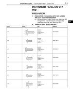
Supplemental Restraint System (SRS) “AIR
BAG” and “SEAT BELT PRE-TENSIONER”
The Supplemental Restraint System such as “AIR BAG” and “SEAT BELT PRE-TENSIONER” used along
with a seat belt, helps to reduce the risk or severity of injury to the driver and front passenger for certain
types of collision. The SRS system composition which is available to NISSAN MODEL L30 is as follows
(The composition varies according to the optional equipment):
b
For a frontal collision
The Supplemental Restraint System consists of driver air bag module (located in the center of the
steering wheel), front passenger air bag module (located on the instrument panel on passenger side),
seat belt pre-tensioners, a diagnosis sensor unit, warning lamp, wiring harness and spiral cable.
b
For a side collision
The Supplemental Restraint System consists of side air bag module (located in the outer side of front
seat), satellite sensor, diagnosis sensor unit (one of components of air bags for a frontal collision),
wiring harness, warning lamp (one of components of air bags for a frontal collision).
Information necessary to service the system safely is included in the RS section of this Service Manual.
WARNING:
b
To avoid rendering the SRS inoperative, which could increase the risk of personal injury or
death in the event of a collision which would result in air bag inflation, all maintenance must
be performed by an authorized NISSAN dealer.
b
Improper maintenance, including incorrect removal and installation of the SRS, can lead to
personal injury caused by unintentional activation of the system. For removal of Spiral Cable
and Air Bag Module, see the RS section.
b
Do not use electrical test equipment on any circuit related to the SRS unless instructed to in
this Service Manual. Spiral cable and wiring harnesses (except “SEAT BELT PRE-TEN-
SIONER”) covered with yellow insulation either just before the harness connectors or for the
complete harness are related to the SRS.
Precautions for On Board Diagnostic (OBD)
System of Engine and A/T
The ECM has an on board diagnostic system. It will light up the malfunction indicator lamp (MIL) to warn
the driver of a malfunction causing emission deterioration.
CAUTION:
b
Be sure to turn the ignition switch “OFF” and disconnect the negative battery terminal before
any repair or inspection work. The open/short circuit of related switches, sensors, solenoid
valves, etc. will cause the MIL to light up.
b
Be sure to connect and lock the connectors securely after work. A loose (unlocked) connec-
tor will cause the MIL to light up due to the open circuit. (Be sure the connector is free from
water, grease, dirt, bent terminals, etc.)
b
Certain systems and components, especially those related to OBD, may use a new style
slide-locking type harness connector.
For description and how to disconnect, refer to EL-5 section (“Description”, “HARNESS CON-
NECTOR”).
b
Be sure to route and secure the harnesses properly after work. The interference of the har-
ness with a bracket, etc. may cause the MIL to light up due to the short circuit.
b
Be sure to connect rubber tubes properly after work. A misconnected or disconnected rubber
tube may cause the MIL to light up due to the malfunction of the EGR system or fuel injection
system, etc.
b
Be sure to erase the unnecessary malfunction information (repairs completed) from the ECM
and TCM (Transmission control module) before returning the vehicle to the customer.
PRECAUTIONS AND PREPARATION
EC-8
Engine Fuel & Emission Control System
AEC878A
GI
MA
EM
LC
EC
FE
CL
MT
AT
FA
RA
BR
ST
RS
BT
HA
EL
IDX
PRECAUTIONS AND PREPARATION
EC-9
SEF289H
Precautions
b
Before connecting or disconnecting the ECM harness
connector, turn ignition switch OFF and disconnect
negative battery terminal. Failure to do so may damage
the ECM because battery voltage is applied to ECM
even if ignition switch is turned off.
SEF308Q
b
When connecting ECM harness connector, tighten
securing bolt until the gap between orange indicators
disappears.
: 3.0 - 5.0 N⅐m(0.3 - 0.5 kg-m, 26 - 43 in-lb)
SEF291H
b
When connecting or disconnecting pin connectors into
or from ECM, take care not to damage pin terminals
(bend or break).
Make sure that there are not any bends or breaks on
ECM pin terminal, when connecting pin connectors.
MEF040D
b
Before replacing ECM, perform Terminals and Refer-
ence Value inspection and make sure ECM functions
properly. Refer to EC-98.
SEF217U
b
After performing each TROUBLE DIAGNOSIS, perform
“OVERALL FUNCTION CHECK” or “DTC (Diagnostic
Trouble Code) CONFIRMATION PROCEDURE”.
The DTC should not be displayed in the “DIAGNOSTIC
TROUBLE CODE CONFIRMATION PROCEDURE” if the
repair is completed. The “OVERALL FUNCTION
CHECK” should be a good result if the repair is com-
pleted.
PRECAUTIONS AND PREPARATION
EC-10
SEF348N
b
When measuring ECM signals with a circuit tester,
never allow the two tester probes to contact.
Accidental contact of probes will cause a short circuit
and damage the ECM power transistor.
b
Do not use ECM ground terminals when measuring
input/output voltage. Doing so may result in damage to
the ECM’s power transistor. Use a ground other than
ECM terminals, such as an engine ground.
GI
MA
EM
LC
EC
FE
CL
MT
AT
FA
RA
BR
ST
RS
BT
HA
EL
IDX
PRECAUTIONS AND PREPARATION
Precautions (Cont’d)
EC-11
Circuit Diagram
WEC121A
ENGINE AND EMISSION CONTROL OVERALL SYSTEM
EC-12
Engine Control Component Parts Location
SEF739Z
GI
MA
EM
LC
EC
FE
CL
MT
AT
FA
RA
BR
ST
RS
BT
HA
EL
IDX
ENGINE AND EMISSION CONTROL OVERALL SYSTEM
EC-13
SEF469UA SEF468UA
ENGINE AND EMISSION CONTROL OVERALL SYSTEM
Engine Control Component Parts Location
(Cont’d)
EC-14
System Diagram
SEF849Z
GI
MA
EM
LC
EC
FE
CL
MT
AT
FA
RA
BR
ST
RS
BT
HA
EL
IDX
ENGINE AND EMISSION CONTROL OVERALL SYSTEM
EC-15
Vacuum Hose Drawing
SEF729Z
Note: Do not use soapy water or any type of solvent while installing vacuum hoses or purge
hoses.
Refer to “System Diagram”, EC-15, for vacuum control system.
ENGINE AND EMISSION CONTROL OVERALL SYSTEM
EC-16
System Chart
Camshaft position sensor
᭤
ECM
Mass air flow sensor
᭤
Engine coolant temperature sensor
᭤
Heated oxygen sensor 1 (front)
᭤
Ignition switch
᭤
Throttle position sensor
᭤
*4
Closed throttle position switch
᭤
Park/neutral position (PNP) switch
᭤
Air conditioner switch
᭤
Knock sensor
᭤
Intake air temperature sensor
᭤
*1
b
EGR temperature sensor
b
EVAP control system pressure
sensor
b
Fuel level sensor
᭤
Battery voltage
᭤
Power steering oil pressure switch
᭤
Vehicle speed sensor
᭤
*1
Fuel tank temperature sensor
᭤
*1
Crankshaft position sensor (OBD)
᭤
*3
Heated oxygen sensor 2 (rear)
᭤
*2
TCM (Transmission control module)
᭤
Electrical load
᭤
Ambient air temperature switch
᭤
Fuel injection & mixture ratio
control
᭤
Injectors
Distributor ignition system
᭤
Power transistor
Idle air control system
᭤
IACV-AAC valve and
IACV-FICD solenoid valve
Fuel pump control
᭤
Fuel pump relay
On board diagnostic system
᭤
Malfunction indicator lamp
(On the instrument panel)
EGR control
᭤
EGRC-solenoid valve
Heated oxygen sensor 1 heater
(front) control
᭤
Heated oxygen sensor 1 heater
(front)
Heated oxygen sensor 2 heater
(rear) control
᭤
Heated oxygen sensor 2 heater
(rear)
EVAP canister purge flow con-
trol
᭤
EVAP canister purge volume
control solenoid valve
Air conditioning cut control
᭤
Air conditioner relay
᭤
b
EVAP canister vent control
valve
b
Vacuum cut valve bypass
valve
*1: These sensors are not used to control the engine system. They are used only for the on board diagnosis.
*2: The DTC related to A/T will be sent to ECM.
*3: This sensor is not used to control the engine system under normal conditions.
*4: This switch will operate in place of the throttle position sensor to control EVAP parts if the sensor malfunctions.
GI
MA
EM
LC
EC
FE
CL
MT
AT
FA
RA
BR
ST
RS
BT
HA
EL
IDX
ENGINE AND EMISSION CONTROL OVERALL SYSTEM
EC-17
Multiport Fuel Injection (MFI) System
INPUT/OUTPUT SIGNAL LINE
Camshaft position sensor
᭤
Engine speed and piston position
ECM
᭤
Injector
Mass air flow sensor
᭤
Amount of intake air
Engine coolant temperature sensor
᭤
Engine coolant temperature
Heated oxygen sensor 1 (front)
᭤
Density of oxygen in exhaust gas
Throttle position sensor
᭤
Throttle position
Throttle valve idle position
Park/neutral position (PNP) switch
᭤
Gear position
Vehicle speed sensor
᭤
Vehicle speed
Ignition switch
᭤
Start signal
Air conditioner switch
᭤
Air conditioner operation
Knock sensor
᭤
Engine knocking condition
Electrical load
᭤
Electrical load signal
Battery
᭤
Battery voltage
Power steering oil pressure switch
᭤
Power steering operation
Heated oxygen sensor 2 (rear)*
᭤
Density of oxygen in exhaust gas
* Under normal conditions, this sensor is not for engine control operation.
BASIC MULTIPORT FUEL INJECTION
SYSTEM
The amount of fuel injected from the fuel injector
is determined by the ECM. The ECM controls the
length of time the valve remains open (injection
pulse duration). The amount of fuel injected is a
program value in the ECM memory. The program
value is preset by engine operating conditions.
These conditions are determined by input signals
(for engine speed and intake air) from both the
camshaft position sensor and the mass air flow
sensor.
VARIOUS FUEL INJECTION
INCREASE/DECREASE COMPENSATION
In addition, the amount of fuel injected is compen-
sated to improve engine performance under vari-
ous operating conditions as listed below.
<Fuel increase>
b
During warm-up
b
When starting the engine
b
During acceleration
b
Hot-engine operation
b
When selector lever is changed from “N” to
“D” (A/T models only)
b
High-load, high-speed operation
<Fuel decrease>
b
During deceleration
b
During high engine speed operation
ENGINE AND EMISSION BASIC CONTROL SYSTEM DESCRIPTION
EC-18
SEF973Z
MIXTURE RATIO FEEDBACK CONTROL (CLOSED
LOOP CONTROL)
The mixture ratio feedback system provides the best air-fuel
mixture ratio for driveability and emission control. The three way
catalyst can then better reduce CO, HC and NOx emissions.
This system uses a heated oxygen sensor 1 (front) in the
exhaust manifold to monitor if the engine operation is rich or
lean. The ECM adjusts the injection pulse width according to the
sensor voltage signal. For more information about the heated
oxygen sensor 1 (front), refer to EC-156, 163. This maintains
the mixture ratio within the range of stoichiometric (ideal air-fuel
mixture).
This stage is referred to as the closed loop control condition.
Heated oxygen sensor 2 (rear) is located downstream of the
three way catalyst. Even if the switching characteristics of the
heated oxygen sensor 1 (front) shift, the air-fuel ratio is con-
trolled to stoichiometric by the signal from the heated oxygen
sensor 2 (rear).
OPEN LOOP CONTROL
The open loop system condition refers to when the ECM detects
any of the following conditions. Feedback control stops in order
to maintain stabilized fuel combustion.
b
Deceleration and acceleration
b
High-load, high-speed operation
b
Malfunction of heated oxygen sensor 1 (front) or its circuit
b
Insufficient activation of heated oxygen sensor 1 (front) at
low engine coolant temperature
b
High engine coolant temperature
b
During warm-up
b
When starting the engine
MIXTURE RATIO SELF-LEARNING CONTROL
The mixture ratio feedback control system monitors the mixture
ratio signal transmitted from the heated oxygen sensor 1 (front).
This feedback signal is then sent to the ECM. The ECM controls
the basic mixture ratio as close to the theoretical mixture ratio as
possible. However, the basic mixture ratio is not necessarily con-
trolled as originally designed. Both manufacturing differences
(i.e., mass air flow sensor hot film) and characteristic changes
during operation (i.e., injector clogging) directly affect mixture ratio.
Accordingly, the difference between the basic and theoretical
mixture ratios is monitored in this system. This is then computed
in terms of “injection pulse duration” to automatically compen-
sate for the difference between the two ratios.
“Fuel trim” refers to the feedback compensation value compared
against the basic injection duration. Fuel trim includes short
term fuel trim and long term fuel trim.
“Short term fuel trim” is the short-term fuel compensation used
to maintain the mixture ratio at its theoretical value. The signal
from the heated oxygen sensor 1 (front) indicates whether the
mixture ratio is RICH or LEAN compared to the theoretical
value. The signal then triggers a reduction in fuel volume if the
mixture ratio is rich, and an increase in fuel volume if it is lean.
“Long term fuel trim” is overall fuel compensation carried out
long-term to compensate for continual deviation of the short
term fuel trim from the central value. Such deviation will occur
due to individual engine differences, wear over time and
changes in the usage environment.
GI
MA
EM
LC
EC
FE
CL
MT
AT
FA
RA
BR
ST
RS
BT
HA
EL
IDX
ENGINE AND EMISSION BASIC CONTROL SYSTEM DESCRIPTION
Multiport Fuel Injection (MFI) System (Cont’d)
EC-19
MEF522D
FUEL INJECTION TIMING
Two types of systems are used.
Sequential multiport fuel injection system
Fuel is injected into each cylinder during each engine cycle
according to the firing order. This system is used when the
engine is running.
MEF523D
Simultaneous multiport fuel injection system
Fuel is injected simultaneously into all four cylinders twice each
engine cycle. In other words, pulse signals of the same width
are simultaneously transmitted from the ECM.
The four injectors will then receive the signals two times for each
engine cycle.
This system is used when the engine is being started and/or if
the fail-safe system (CPU) is operating.
FUEL SHUT-OFF
Fuel to each cylinder is cut off during deceleration or operation
of the engine at excessively high speeds.
Distributor Ignition (DI) System
INPUT/OUTPUT SIGNAL LINE
Camshaft position sensor
᭤
Engine speed and piston position
ECM
᭤
Power tran-
sistor
Mass air flow sensor
᭤
Amount of intake air
Engine coolant temperature sensor
᭤
Engine coolant temperature
Throttle position sensor
᭤
Throttle position
Throttle valve idle position
Vehicle speed sensor
᭤
Vehicle speed
Ignition switch
᭤
Start signal
Knock sensor
᭤
Engine knocking
Park/Neutral position (PNP) switch
᭤
Gear position
Battery
᭤
Battery voltage
TCM (Transmission control module)
᭤
A/T gear shifting
ENGINE AND EMISSION BASIC CONTROL SYSTEM DESCRIPTION
Multiport Fuel Injection (MFI) System (Cont’d)
EC-20
SEF742M
SYSTEM DESCRIPTION
The ignition timing is controlled by the ECM to maintain the best
air-fuel ratio for every running condition of the engine.
The ignition timing data is stored in the ECM. This data forms
the map shown.
The ECM receives information such as the injection pulse width
and camshaft position sensor signal. Computing this information,
ignition signals are transmitted to the power transistor.
e.g., N: 1,800 rpm, Tp: 1.50 msec
A°BTDC
During the following conditions, the ignition timing is revised by
the ECM according to the other data stored in the ECM.
b
At starting
b
During warm-up
b
At idle
b
At low battery voltage
b
During acceleration
The knock sensor retard system is designed only for emergen-
cies. The basic ignition timing is programmed within the anti-
knocking zone, if recommended fuel is used under dry condi-
tions. The retard system does not operate under normal driving
conditions.
If engine knocking occurs, the knock sensor monitors the con-
dition. The signal is transmitted to the ECM. The ECM retards
the ignition timing to eliminate the knocking condition.
Air Conditioning Cut Control
INPUT/OUTPUT SIGNAL LINE
Air conditioner switch
᭤
Air conditioner “ON” signal
ECM
᭤
Air
conditioner
relay
Throttle position sensor
᭤
Throttle valve opening angle
Camshaft position sensor
᭤
Engine speed
Engine coolant temperature sensor
᭤
Engine coolant temperature
Ignition switch
᭤
Start signal
Vehicle speed sensor
᭤
Vehicle speed
Power steering oil pressure switch
᭤
Power steering operation
SYSTEM DESCRIPTION
This system improves engine operation when the
air conditioner is used.
Under the following conditions, the air conditioner
is turned off.
b
When the accelerator pedal is fully depressed.
b
When cranking the engine.
b
At high engine speeds.
b
When the engine coolant temperature
becomes excessively high.
b
When operating power steering during low
engine speed or low vehicle speed.
b
When engine speed is excessively low.
GI
MA
EM
LC
EC
FE
CL
MT
AT
FA
RA
BR
ST
RS
BT
HA
EL
IDX
ENGINE AND EMISSION BASIC CONTROL SYSTEM DESCRIPTION
Distributor Ignition (DI) System (Cont’d)
EC-21
Fuel Cut Control (at no load & high engine
speed)
INPUT/OUTPUT SIGNAL LINE
Vehicle speed sensor
᭤
Vehicle speed
ECM
᭤
Injectors
Park/Neutral position (PNP) switch
᭤
Neutral position
Throttle position sensor
᭤
Throttle position
Engine coolant temperature sensor
᭤
Engine coolant temperature
Camshaft position sensor
᭤
Engine speed
If the engine speed is above 4,000 rpm with no load, (for
example, in neutral and engine speed over 4,000 rpm) fuel will
be cut off after some time. The exact time when the fuel is cut
off varies based on engine speed.
Fuel cut will operate until the engine speed reaches 2,000 rpm,
then fuel cut is cancelled.
NOTE:
This function is different from deceleration control listed
under “Multiport Fuel Injection (MFI) System”, EC-18.
ENGINE AND EMISSION BASIC CONTROL SYSTEM DESCRIPTION
EC-22
Description
SEF222U
The evaporative emission system is used to reduce hydrocar-
bons emitted into the atmosphere from the fuel system. This
reduction of hydrocarbons is accomplished by activated char-
coals in the EVAP canister.
The fuel vapor in the sealed fuel tank is led into the EVAP can-
ister which contains activated carbon and the vapor is stored
there when the engine is not operating or when refueling to the
fuel tank.
The vapor in the EVAP canister is purged by the air through the
purge line to the intake manifold when the engine is operating.
EVAP canister purge volume control solenoid valve is controlled
by engine control module. When the engine operates, the flow
rate of vapor controlled by EVAP canister purge volume control
solenoid valve is proportionally regulated as the air flow
increases.
EVAP canister purge volume control solenoid valve also shuts
off the vapor purge line during decelerating and idling.
SEF470U
Inspection
EVAP CANISTER
Check EVAP canister as follows:
1. Pinch the fresh air hose.
2. Blow air into port
᭺
A
and check that air flows freely through
port
᭺
B
.
GI
MA
EM
LC
EC
FE
CL
MT
AT
FA
RA
BR
ST
RS
BT
HA
EL
IDX
EVAPORATIVE EMISSION SYSTEM
EC-23
AEC778A
TIGHTENING TORQUE
Tighten EVAP canister as shown in the figure.
Make sure new O-ring is installed properly between EVAP
canister and EVAP vent control valve.
SEF427N
SEF943S
FUEL TANK VACUUM RELIEF VALVE (Built into fuel
filler cap)
1. Wipe clean valve housing.
2. Check valve opening pressure and vacuum.
Pressure:
16.0 - 20.0 kPa (0.163 - 0.204 kg/cm
2
, 2.32 - 2.90
psi)
Vacuum:
−6.0 to −3.3 kPa (−0.061 to −0.034 kg/cm
2
, −0.87
to −0.48 psi)
3. If out of specification, replace fuel filler cap as an assembly.
CAUTION:
Use only a genuine fuel filler cap as a replacement. If an
incorrect fuel filler cap is used, the MIL may come on.
VACUUM CUT VALVE
Refer to EC-420.
EVAPORATIVE EMISSION (EVAP) CANISTER PURGE
VOLUME CONTROL SOLENOID VALVE
Refer to EC-386.
FUEL TANK TEMPERATURE SENSOR
Refer to EC-240.
EVAPORATIVE EMISSION SYSTEM
Inspection (Cont’d)
EC-24
SEF462UH
EVAP SERVICE PORT
Positive pressure is delivered to the evaporator system through
the evaporator service port. If fuel vapor leakage in the evapo-
rator system occurs, use a leak detector to locate the leak.
PEF658U
SEF200U
AEC779A
AEC780A
How to detect fuel vapor leakage
CAUTION:
b
Never use compressed air or a high pressure pump.
b
Do not start engine.
b
Do not exceed 4.12 kPa (0.042 kg/cm
2
, 0.6 psi) of pres-
sure in EVAP system.
NOTE:
Improper installation of adapter to the service port may
cause a leak.
1. Attach the EVAP service port adapter securely to the
EVAP service port.
2. Also attach the pressure pump and hose.
3. Turn ignition switch “ON”.
4. Select the “EVAP SYSTEM CLOSE” of “WORK SUP-
PORT MODE” with CONSULT-II.
5. Touch “START”. A bar graph (Pressure indicating dis-
play) will appear on the screen.
6. Apply positive pressure to the EVAP system until the
pressure indicator reaches the middle of the bar
graph.
7. Locate the leak using a leak detector. Refer to
“Evaporative Emission Line Drawing”, EC-26.
OR
1. Attach the EVAP service port adapter securely to the
EVAP service port and pressure pump with pressure
gauge to the EVAP service port.
2. Apply battery voltage to between the terminals of
both EVAP canister vent control valve and vacuum
cut valve bypass valve to make a closed EVAP sys-
tem.
3. To locate the leak, deliver positive pressure to the
EVAP system until pressure gauge points reach 1.38
to 2.76 kPa (0.014 to 0.028 kg/cm
2
, 0.2 to 0.4 psi).
4. Locate the leak using a leak detector. Refer to
“Evaporative Emission Line Drawing”, EC-26.
GI
MA
EM
LC
EC
FE
CL
MT
AT
FA
RA
BR
ST
RS
BT
HA
EL
IDX
EVAPORATIVE EMISSION SYSTEM
Inspection (Cont’d)
EC-25