Toyota camry 2006 2011 2AZ FE charging hệ thống charge toyota camry 2AZ FE đời 2006 2011
Bạn đang xem bản rút gọn của tài liệu. Xem và tải ngay bản đầy đủ của tài liệu tại đây (1.92 MB, 21 trang )
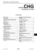
2AZ-FE CHARGING – CHARGING SYSTEM
CH–1
CH
CHARGING SYSTEM
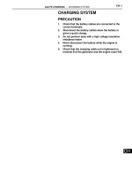
PRECAUTION
1. Check that the battery cables are connected to the
correct terminals.
2. Disconnect the battery cables when the battery is
given a quick charge.
3. Do not perform tests with a high voltage insulation
resistance tester.
4. Never disconnect the battery while the engine is
running.
5. Check that the charging cable nut is tightened on
terminal B of the generator and the engine room R/B.
CH–2
2AZ-FE CHARGING – CHARGING SYSTEM
CH
PARTS LOCATION
GENERATOR
COMBINATION METER
-CHARGE WARNING LIGHT
ECM
ENGINE ROOM R/B
-ALT-S FUSE
-GAUGE NO. 1 FUSE
-GAUGE NO. 2 FUSE
-ALT FUSE
INSTRUMENT PANEL J/B
A135520E01
2AZ-FE CHARGING – CHARGING SYSTEM
CH–3
CH
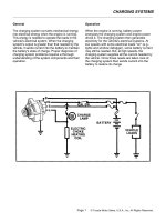
SYSTEM DIAGRAM
From Battery
From IG1 Relay
From
Ignition Switch
ALT-S
GAUGE No. 1
GAUGE No. 2
F1
13
IG+
IG+
Charge
CHG-
F1
23
Combination Meter
ECM
IC
Regulator
C18
C18
C18
C18
4
2
1
3
M
S
IG
L
C24 ALT
50
Generator
C19
1
B
ALT
FL MAIN
Battery
A135064E01
CH–4
2AZ-FE CHARGING – CHARGING SYSTEM
CH
PROBLEM SYMPTOMS TABLE
Result
Symptom Suspected area See page
Charge Warning Light Comes ON while Driving
1. Clutch pulley
CH-7
2. Generator assembly
Noise Occurs from Generator while Engine is Running
1. V-ribbed belt
CH-82. Clutch pulley
3. Generator assembly
2AZ-FE CHARGING – CHARGING SYSTEM
CH–5
CH
ON-VEHICLE INSPECTION
1. CHECK BATTERY ELECTROLYTE LEVEL
(a) Check the electrolyte level.
(1) If the electrolyte level is low, replace the battery
(or add distilled water) and check the charging
system.
2. CHECK BATTERY SPECIFIC GRAVITY
(a) Check the color of the indicator.
Result
3. CHECK BATTERY VOLTAGE
(a) If it has not been 20 minutes since you drove the
vehicle or since the engine was stopped, turn the
ignition switch to the ON position and turn on the
electrical systems (headlight, blower motor, rear
defogger, etc.) for 60 seconds. This will remove the
surface charge from the battery.
(b) Turn off the ignition switch and the electrical
systems.
(c) Measure the battery voltage between the negative (-
) and positive (+) terminals of the battery.
Standard voltage:
12.5 to 12.9 V at 20°C (68°F)
HINT:
If the voltage is below the specification, charge the
battery.
4. CHECK BATTERY TERMINAL
(a) Check that the battery terminals are not loose or
corroded.
If the terminals are corroded, clean them.
5. CHECK FUSES
(a) Measure the resistance of the ALT fuse, ALT-S fuse,
GAUGE No. 1 fuse and GAUGE No. 2 fuse.
Standard resistance:
Below 1 Ω
If the result is not as specified, replace the fuses as
necessary.
6. CHECK V-RIBBED BELT
(a) Check the belt for wear, cracks or other signs of
damage.
If any of the following defects is found, replace the
V-ribbed belt.
• The belt is worn out, cracked, or the cords are
exposed.
• The cracks reach the cords in more than one
place.
• The belt has chunks missing from the ribs.
Green
Dark
Clear or Light Yellow
A115815E01
Indicator color Condition
Green Good
Dark Charging necessary
Clear or light yellow Replacement necessary
A081052E01
B000543
CH–6
2AZ-FE CHARGING – CHARGING SYSTEM
CH
(b) Check that the belt fits properly in the ribbed
grooves.
HINT:
Check with your hand to confirm that the belt has
not slipped out of the groove on the bottom of the
pulley.
If it has slipped out, replace the V-ribbed belt. Install
a new V-ribbed belt correctly.
7. VISUALLY CHECK GENERATOR WIRING
(a) Check that the generator wiring is in good condition.
If the condition is not good, repair or replace the
generator wire.
8. LISTEN FOR ABNORMAL NOISES FROM
GENERATOR
(a) Check that there is no abnormal noise from the
generator while the engine is running.
If there is abnormal noise, replace the pulley or
generator.
9. CHECK CHARGE WARNING LIGHT CIRCUIT
(a) Turn the ignition switch to the ON position. Check
that the charge warning light comes on.
(b) Start the engine and check that the light goes off.
If the light does not operate as specified,
troubleshoot the charge warning light circuit.
10. CHECK CHARGING CIRCUIT WITHOUT LOAD
(a) According to the following procedure, connect an
ammeter and voltmeter as shown in the illustration.
(1) Disconnect the wire from terminal B of the
generator and connect it to the negative (-) lead
of the ammeter.
(2) Connect the positive (+) lead of the ammeter to
terminal B of the generator.
(3) Connect the positive (+) lead of the voltmeter to
positive (+) terminal of the battery.
(4) Ground the negative (-) lead of the voltmeter.
(b) Check the charging circuit.
(1) While keeping the engine speed at 2,000 rpm,
check the readings on the ammeter and
voltmeter.
Standard amperage:
10 A or less
Standard voltage:
13.2 to 14.8 V
If the results are not as specified, replace the
generator assembly.
HINT:
• If the battery is not fully charged, the
ammeter reading may be more than the
standard amperage. In this case, increase
electrical load by operating devices such as
the wiper motor and rear window defogger.
Then, recheck the reading on the ammeter.
CORRECT INCORRECT
B000540E03
V
A
Disconnect
Wire from
Terminal B
Ammeter
Battery
Battery
Generator
Voltmeter
A110265E04
2AZ-FE CHARGING – CHARGING SYSTEM
CH–7
CH
11. CHECK CHARGING CIRCUIT WITH LOAD
(a) Keep the engine speed at 2,000 rpm, turn on the
high beam headlights, and turn the heater blower
switch to the "HI" position.
(b) Check the reading on the ammeter.
Standard amperage:
30 A or more
If the ammeter reading is less than the standard
amperage, replace the generator assembly.
HINT:
• If the battery is fully charged, the ammeter
reading may be less than the standard
amperage. In this case, increase electrical load
by operating devices such as the wiper motor
and rear window defogger. Then, recheck the
reading on the ammeter.
CH–8
2AZ-FE CHARGING – CHARGING SYSTEM
CH
INSPECTION PROCEDURE
(a) Check the lock function with the pulley installed in the
vehicle.
(1) Visually check that the rotor in the generator
operates with the engine started.
(b) Check the lock function with the pulley removed from the
vehicle.
(1) Remove the generator pulley cap. Using SST, hold
the generator rotor.
(2) Turn the clutch pulley clockwise and check that the
outer ring locks.
OK:
The outer ring locks.
SST 09820-63020
NG
OK
(a) Start the engine and visually check looseness of the
clutch pulley.
OK:
The clutch pulley is not loose.
NG
OK
Charge Warning Light Comes ON while Driving
1
CHECK LOCK FUNCTION OF CLUTCH PULLEY
Free Lock
A130538E01
REPLACE CLUTCH PULLEY
2
CHECK LOCK OF CLUTCH PULLEY
TIGHTEN CLUTCH PULLEY TO THE
SPECIFIED TORQUE
REPLACE GENERATOR ASSEMBLY
2AZ-FE CHARGING – CHARGING SYSTEM
CH–9
CH
INSPECTION PROCEDURE
(a) Check the tension of the belt by pushing it down with a
finger.
OK:
The tension of the belt is enough.
NG
OK
(a) Check the V-ribbed belt for wear.
OK:
The V-ribbed belt is not worn.
NG
OK
(a) Check the clutch pulley groove for wear or other defects.
OK:
The clutch pulley groove is not damaged.
NG
OK
(a) Perform a driving test and check if noise occurs when
decelerating.
OK:
Noise does not occur.
NG
OK
Noise Occurs from Generator while Engine is Running
1
CHECK LOOSENESS OF V-RIBBED BELT
REPLACE V-RIBBED BELT TENSIONER
ASSEMBLY
2
CHECK V-RIBBED BELT FOR WEAR
REPLACE V-RIBBED BELT
3
CHECK CLUTCH PULLEY FOR WEAR
REPLACE CLUTCH PULLEY
4
CHECK FOR NOISE WHILE CLUTCH PULLEY IS OPERATING
REPLACE CLUTCH PULLEY
REPLACE GENERATOR ASSEMBLY
2AZ-FE CHARGING – GENERATOR
CH–9
CH
ENGINE2AZ-FE CHARGING
GENERATOR
COMPONENTS
GENERATOR ASSEMBLY
N*m (kgf*cm, ft.*lbf)
: Specified torque
9.8 (100, 87 in.*lbf)
21 (215, 16)
52 (530, 38)
8.4 (86, 74 in.*lbf)
V-RIBBED BELT
FRONT FENDER APRON SEAL RH ENGINE UNDER COVER RH
A133568E01
CH–10
2AZ-FE CHARGING – GENERATOR
CH
GENERATOR BRUSH
HOLDER ASSEMBLY
GENERATOR
CLUTCH PULLEY
GENERATOR DRIVE
END FRAME BEARING
GENERATOR ROTOR ASSEMBLY
GENERATOR TERMINAL
INSULATOR
GENERATOR COIL ASSEMBLY
GENERATOR REAR
END COVER
GENERATOR
PULLEY CAP
GENERATOR DRIVE END FRAME
BEARING
RETAINER PLATE
GENERATOR WASHER
CORD CLIP
N*m (kgf*cm, ft.*lbf)
: Specified torque
Non-reusable part
4.6 (47, 41 in.*lbf)
111 (1,125, 81)
x3
1.8 (18, 16 in.*lbf)
x2
4.6 (47, 41 in.*lbf)
5.8 (59, 51 in.*lbf)
x4
2.3 (23, 20 in.*lbf)
x4
A135515E01
2AZ-FE CHARGING – GENERATOR
CH–11
CH
REMOVAL
1. DISCONNECT CABLE FROM NEGATIVE BATTERY
TERMINAL
2. REMOVE FRONT WHEEL RH
3. REMOVE ENGINE UNDER COVER RH
4. REMOVE FRONT FENDER APRON SEAL RH
5. REMOVE V-RIBBED BELT (See page EM-6)
6. REMOVE GENERATOR ASSEMBLY
(a) Disconnect the generator connector.
(b) Remove the nut and disconnect the wire harness
from terminal B.
(c) Remove the bolt and wire harness clamp bracket.
(d) Remove the wire harness clamps.
(e) Remove the 2 bolts and generator assembly.
DISASSEMBLY
1. REMOVE GENERATOR CLUTCH PULLEY
(a) Using a screwdriver, puncture the center of the
generator pulley cap and pry it off.
NOTICE:
Do not reuse the generator pulley cap.
(b) Set SST (A) and (B).
SST 09820-63020
(c) Clamp SST (A) in a vise.
A135170
A133567
A126771
SST (A)
SST (B)
A124115E01
CH–12
2AZ-FE CHARGING – GENERATOR
CH
(d) Place the rotor shaft end into SST (A).
(e) Fit SST (B) to the clutch pulley.
(f) Loosen the pulley by turning SST (B) in the direction
shown in the illustration.
(g) Remove the generator assembly from the SST.
(h) Remove the clutch pulley from the rotor shaft.
2. REMOVE GENERATOR BRUSH HOLDER ASSEMBLY
(a) Place the generator assembly on the clutch pulley.
(b) Remove the 3 nuts and generator rear end cover.
SST (A)
SST (B)
Rotor Shaft
A128605E01
Clutch Pulley
SST (B)
SST (B)
A128606E01
SST (B)
A128607E01
A128608
A128610
2AZ-FE CHARGING – GENERATOR
CH–13
CH
3. REMOVE GENERATOR TERMINAL INSULATOR
(a) Remove the terminal insulator.
4. REMOVE GENERATOR BRUSH HOLDER ASSEMBLY
(a) Remove the 2 screws and generator brush holder.
5. REMOVE GENERATOR ROTOR ASSEMBLY
(a) Remove the 4 bolts.
(b) Remove the bolt and cord clip.
(c) Using SST, remove the coil.
SST 09950-40011 (09951-04020, 09952-04010,
09953-04020, 09954-04010, 09955-04071,
09957-04010, 09958-04011)
A128609
A128611
A128612
A128613
Hold
Turn
SST
SST
A128614E01
CH–14
2AZ-FE CHARGING – GENERATOR
CH
6. REMOVE GENERATOR ROTOR ASSEMBLY
(a) Remove the washer.
(b) Remove the generator rotor.
7. REMOVE GENERATOR DRIVE END FRAME
BEARING
(a) Remove the 4 screws and bearing retainer.
(b) Using SST and a hammer, tap out the bearing.
SST 09950-60010 (09951-00250), 09950-70010
(09951-07100)
INSPECTION
1. INSPECT GENERATOR CLUTCH PULLEY
(a) Hold the center of the pulley, and confirm that the
outer ring turns counterclockwise and does not turn
clockwise.
If the result is not as specified, replace the
generator pulley with clutch.
A118365E01
A128615
A128617
SST
A128618E01
Free Lock
A130538E01
2AZ-FE CHARGING – GENERATOR
CH–15
CH
2. INSPECT GENERATOR BRUSH HOLDER ASSEMBLY
(a) Using vernier calipers, measure the brush length.
Standard length:
9.5 to 11.5 mm (0.374 to 0.453 in.)
Minimum length:
4.5 mm (0.177 in.)
If the brush length is less than the minimum, replace
the generator brush holder assembly.
3. INSPECT GENERATOR ROTOR ASSEMBLY
(a) Check the appearance.
(1) Check that the bearing is not rough or worn.
OK:
The bearing rotates smoothly.
If the result is not as specified, replace the
generator rotor assembly.
(b) Check the resistance.
(1) Measure the resistance between the slip rings.
Standard resistance
If the result is not as specified, replace the
generator rotor assembly.
(2) Measure the resistance between the slip ring
and rotor core.
Standard resistance
If the result is not as specified, replace the
generator rotor assembly.
(c) Check the slip ring diameter.
(1) Using vernier calipers, measure the slip ring
diameter.
Standard diameter:
14.2 to 14.4 mm (0.559 to 0.567 in.)
Minimum diameter:
14 mm (0.551 in.)
If the diameter is less than the minimum,
replace the generator rotor assembly.
Length
A079305E04
A097469E01
Slip Ring
A097476E02
Condition Specified condition
Approx. 20°C (68°F) 2.3 to 2.7 Ω
Rotor Core
Slip Ring
A097477E02
Tester condition Specified condition
Slip ring - Rotor core 1 MΩ or higher
A097470E02
CH–16
2AZ-FE CHARGING – GENERATOR
CH
4. INSPECT GENERATOR DRIVE END FRAME
BEARING
(a) Check that the bearing is not rough or worn.
OK:
The bearing rotates smoothly.
If the bearing does not rotate smoothly, replace the
bearing.
REASSEMBLY
1. INSTALL GENERATOR DRIVE END FRAME
BEARING
(a) Using SST and a press, press in a new generator
drive end frame bearing.
SST 09950-60010 (09951-00250), 09950-70010
(09951-07100)
(b) Fit the tabs on the retainer plate into the cutouts on
the drive end frame to install the retainer plate.
(c) Install the 4 screws.
Torque: 2.3 N*m (23 kgf*cm, 20 in.*lbf)
2. INSTALL GENERATOR ROTOR ASSEMBLY
(a) Place the drive end frame on the clutch pulley.
(b) Install the generator rotor onto the generator
rectifier end frame.
(c) Place a new generator washer on the generator
rotor.
A097471E01
SST
A128619E01
Tab
Cutout
A128620E01
A128615
A118365E01
2AZ-FE CHARGING – GENERATOR
CH–17
CH
3. INSTALL GENERATOR COIL ASSEMBLY
(a) Using SST and a press, press in the generator coil
assembly to the drive end frame.
SST 09612-70100 (09612-07240)
(b) Tighten the 4 bolts.
Torque: 5.8 N*m (59 kgf*cm, 51 in.*lbf)
(c) Install the cord clip with the bolt.
Torque: 4.6 N*m (47 kgf*cm, 41 in.*lbf)
4. INSTALL GENERATOR BRUSH HOLDER ASSEMBLY
(a) While pushing the 2 brushes into the generator
brush holder, insert a 1.0 mm (0.039 in.) pin into the
generator brush holder.
(b) Install the generator brush holder with the 2 screws.
Torque: 1.8 N*m (18 kgf*cm, 16 in.*lbf)
SST
A128621E01
A128612
A128613
Pin
A079315E04
A128622
CH–18
2AZ-FE CHARGING – GENERATOR
CH
(c) Pull the pin out of the generator brush holder.
5. INSTALL GENERATOR TERMINAL INSULATOR
(a) Install the terminal insulator onto the generator
rectifier end frame.
6. INSTALL GENERATOR REAR END COVER
(a) Install the generator rear end cover with the 3 nuts.
Torque: 4.6 N*m (47 kgf*cm, 41 in.*lbf)
7. INSTALL GENERATOR CLUTCH PULLEY
(a) Temporarily install the clutch pulley onto the rotor
shaft.
(b) Set SST (A) and (B).
SST 09820-63020
(c) Clamp SST (A) in a vise.
(d) Place the rotor shaft end into SST (A).
Pull out
Pin
A130537E01
A128623
A128610
SST (A)
SST (B)
A128084E01
SST (A)
SST (B)
Rotor Shaft
A128605E01
2AZ-FE CHARGING – GENERATOR
CH–19
CH
(e) Fit SST (B) to the clutch pulley.
(f) Tighten the pulley by turning SST (B) in the direction
shown in the illustration.
Torque: 111 N*m (1,125 kgf*cm, 81 ft.*lbf)
NOTICE:
The torque shown above should be used for
tightening without using the SST. When the SST
is used for tightening, the torque should be
calculated based on the length of the SST (See
page IN-6).
(g) Remove the generator assembly from the SST.
(h) Check that the clutch pulley rotates smoothly.
(i) Install a new clutch pulley cap to the clutch pulley.
INSTALLATION
1. INSTALL GENERATOR ASSEMBLY
(a) Confirm that the wire harness of the crankshaft
position sensor is secured to the wire harness
clamp bracket through the back of the rib of the
timing chain cover.
(b) Install the generator assembly with the 2 bolts.
Torque: Bolt A
21 N*m (215 kgf*cm, 16 ft.*lbf)
Bolt B
52 N*m (530 kgf*cm, 38 ft.*lbf)
Clutch Pulley
SST (B)
SST (B)
A128606E01
100 mm (3.937 in.)
SST (B)
SST (B)
A135051E01
Wire Harness
Clamp Bracket
Rib
A097394E03
A
B
A133567E01
CH–20
2AZ-FE CHARGING – GENERATOR
CH
(c) Install the generator wire to terminal B with the nut.
Torque: 9.8 N*m (100 kgf*cm, 87 in.*lbf)
(d) Install the clamp bracket with the bolt.
Torque: 8.4 N*m (86 kgf*cm, 74 in.*lbf)
(e) Attach the clamp and connect the generator
connector to the generator.
2. INSTALL V-RIBBED BELT (See page EM-6)
3. INSTALL FRONT FENDER APRON SEAL RH
4. INSTALL ENGINE UNDER COVER RH
5. INSTALL FRONT WHEEL RH (See page EM-7)
6. CONNECT CABLE TO NEGATIVE BATTERY
TERMINAL (See page EM-120)
A135170