Road traffic control gesture recognition using Microsoft Kinect
Bạn đang xem bản rút gọn của tài liệu. Xem và tải ngay bản đầy đủ của tài liệu tại đây (664.39 KB, 32 trang )
Trường Đại học Công Nghệ
CÔNG TRÌNH DỰ THI
GIẢI THƯỞNG “SINH VIÊN NGHIÊN CỨU KHOA HỌC”
NĂM 2011
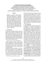
Tên công trình:Road traffic control gesture recognition using Microsoft Kinect
Nhóm thực hiện:
Lê Quốc Khánh Nam
Phạm Chính Hữu Nam
Lớp: K53CA Khoa: Công nghệ thông tin
Người hướng dẫn:
TS. Lê Thanh Hà
Hà Nội, 3/2012
AbstractOverview
Our study concentrates on building an intelligent system in smart vehicle.
Specifically, this system identifies the traffic control commands of policeman to
propose right decision to driver. Our work enables smart vehicle to detect and
recognize traffic officer on the road. Technically, we use a built-in depth sensorof
Microsoft Kinect to capture image for recognition system. The feature characteristics
of depth image is depth information providing (same as 3D information), color and
texture invariance which is the difference from RGB camera.By incorporatingspatial-
temporal invariance into the geometric features and applying machine learning
classifier model, we are able to predict traffic control command from depth
information captured. The construction of feature vector is based on relative angles
between body parts of human which possibly be extractedfrom Kinect. We present
experimental result on a test data of more than 30,000 frames whose is 6 kind of
traffic commands. Using both Kmeans andSupport vector machine (SVM)to classify,
the betterresult is about 99.8%by SVM classifier. Moreover, the application of this
system runssteadily in real-time.
2
Contents
3
Index of Figure and Table
4
1. Problem statement
Human traffic control is preferred for developing nations because of the relatively
fewer cars, the few major intersections, and the low cost of human traffic-controllers
[3]. In human traffic control environment, drivers must follow the directions given
from the traffic police officer in forms of human body gestures. To improve the safety
of the drivers, our research team is developing a novel method to automatically
recognize the traffic control gestures.
There have been a few methods developed for traffic control gesture recognition in the
literature. Fan Guo et al. [6] recognized police gestures from the corresponding body
parts on the color image plane. The detection results of this method were heavily
affected by background and outdoor illumination because traffic police in a complex
scene is detected by extracting the reflective traffic vest of the traffic police using
color thresholding. Yuan Tao et al. [23] fixed on-body sensors on the back of each
hand of police to extract gesture data. Although this accelerometer-based sensor may
output accurate hand positions, it gives extra hindrance to the police and requires a
unique communication protocol for vehicles. Meghna Singh et all. [11] used Radon
transform to recognize air marshals’ hand gestures for steering aircraft on the runway.
However, since a relatively stationary background of video sequence is required this
method is not practical for traffic scene.
Human gesture recognition for traffic control purpose can be related with that for
human-robot interaction. Bauer et al. [6] presented an interaction system where a
robot asks a human for directions, and then interprets the given directions. This
system includes a vision component where the full body pose is inferred from a stereo
image pair. However, this fitting process is rather slow and does not work in real time.
Waldherr et al. [5] presented a template-based hand gesture recognition system for a
mobile robot, with gestures for the robot to stop or follow, and rudimentary pointing.
As the gesture system is based on a color-based tracker, several limitations are
imposed on the types of clothing and contrast with the background. In [16], Van den
Bergh et al. introduced a real-time hand gesture interaction system based on a Time-
of-Flight (ToF) camera. Both the depth images from the ToF camera and the color
image from the RGB camera are used for a Haarletbased hand gesture classification.
Similar ToF-based systems were also described in the literature [18][5][21]. The use
of the ToF camera allows for a recognition system robust to all colors of clothing, to
background noise and to other people standing around. However, ToF cameras are
5
expensive and suffer from a very low resolution and a narrow angle of view. M. V.
Bergh et al. [13] implemented a pointing hand gesture recognition algorithm based on
Kinect sensor to tell a robot where to go. Although this system can be used for real-
time robot control application, it can not be applied directly to traffic control situation
because of the limitation of meaning gestures presented only by pointing of hands.
In Vietnamese traffic control system, a human traffic controller is able to assess the
traffic in visual range around the traffic intersection. Based on his observation, he
makes intelligent decisions and give traffic signals in forms of his arms’ directions
and movements to all incoming vehicle drivers. In this research, we only consider the
directions of arms for classifying traffic control commands. Based on the observation
at real traffic intersection in Vietnam, we categorize control command into tree types
as shown in Table 1.
Type Command Human arm directions
1 Stop all the vehicle in every road
directions.
Left/right arm raises straight
up to
2 Stop all vehicle in front of and
behind the traffic police officer.
Left/right arm raises to the
left/right to
3 Stop all vehicle on the right of and
behind the traffic police officer.
Left/right arm raises to the
front to
Table 1. Three types of traffic control command
From these control command types, six traffic gestures can be constructed. Each
traffic gesture is a combination of the arms’ directions as listed in Table 2.
Gesture Human arm directions Command type
1 left hand raises straight up 1
2 right hand raises straight up 1
3 left hand raises to the left 2
4 right hand raises to the right 2
5 left hand raises to the front 3
6 right hand raises to the front 3
Table 2. Six traffic gestures defined.
As stated in previous section, human parts including arm directions can be presented
by a skeleton model consisting of 15 joints, namely, head, neck, torso, left shoulder,
right shoulder, left elbow, right elbow, left hand, right hand, left hip, right hip, left
knee, right knee, left foot, right foot. Therefore, the recognition of traffic gestures can
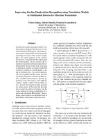
be done using skeleton model. Figure 3 depicts two examples of traffic gestures and
their skeletal joints.
6
Since skeleton model visualizes human parts simply by a set of relative joints,
skeleton appears to have significant recognition advantage other than depth and color
information. Therefore, instead of directly doing human parts recognition using depth
and color images, we do skeleton recognition after preprocessing the Kinect’s depth
images by using OpenNI library.
Figure 1.Traffic gestures and skeletal joints
In this research, we separate two type of gesture for recognition: static and dynamic
gestures. Based on the description in Table 1, obviously the commands of traffic
officer are considered as static gestures. We completed successfully the system for
recognizing static gesture, and doon-going approach of dynamic gesture recognition to
improve and extend the various kind of human gestures.
Our completed approach presents a real-time human body gesture recognition method
for road traffic control purpose. In this method, 6 body gestures used by police officer
to control the flow direction of vehicles at a common intersection can be recognized
by Kinect from Microsoft. In order to recognize the defined gesture, a depth sensor is
installed is used to generate depth map of the scene where traffic police officer
stands. Then, a skeleton presentation of police officer body is computed. A feature
vector is created based on the joints of the skeleton model.
7
2. Related work
2.1Human body parts recognition using Microsoft Kinect
The approach of using RGB images or video for human detection and recognition
faces challenging problems due to variation in pose, clothing, lighting conditions and
complexity of backgrounds. These will result in the drop of detection and recognition
accuracy or the increase of computational cost. Therefore, the approach of using 3D
reconstruction information obtained from depth cameras has been focusedrecently[22]
[10][9][24]. Depth images have several advantages over 2D intensity images: range
images are robust to the change in color and illumination; range images are simple
representations of 3D information. However, earlier range sensors were expensive and
difficult to use in human environments because of lasers.
a. Microsoft Kinect for obtaining depth images
Recently, Microsoft has launched the Kinect, a peripheral designed as a video-game
con-trolling device for the Microsoft’s X-Box Console. But despite its initial purpose,
it facilitates the research in human detection, tracking and activity analysis thanks to
the combination of its high capabilities and low cost. The sensor provides a depth
resolution similar to the ToF cameras, but at a cost several times lower. To obtain the
depth information, the device uses the Prime Sense’s Light Coding Technology [19],
in which Infra-Red (IR) light is projected as a dot pattern to the scene. This projected
light pattern creates textures that helps finding the correspondence between pixels
even in shiny or texture-less objects or with harsh lighting conditions. In addition,
because the pattern is fixed, there is no time domain variation other than the
movements of the objects in the field of view of the camera. This ensures a precision
similar to the ToF, but Prime Sense’s mounted IR receiver is a standard CMOS
sensor, which reduces the price of the device drastically.
8
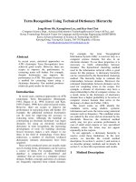
Figure 2. Block Diagram of the Prime Sense Reference Design [20]
Figure 2 depicts the block diagram of the reference design used by the Kinect
sensor [20]. The sensor is composed of one IR emitter, responsible of emitting the
light pattern to the scene, a depth sensor responsible of capturing the emitted pattern.
It is also equipped with a standard RGB sensor that records the scene in visible light.
Both depth and RGB sensors have a resolution of 640x480 pixels. The matching
calibration process between the depth and the RGB pixels and the 3D reconstruction
are handled at chip level.
b. Human body pose recognition using depth images
For human body pose recognition purpose, Prime Sense has created a open
source library, Open Natural Interaction (OpenNI) [15], to promote the natural
interaction. OpenNI provides several algorithms for the use of Prime Sense’s
compliant depth cameras, including Microsoft Kinect, in natural interaction fields.
Some of these algorithms provide the extraction and tracking of a skeleton model
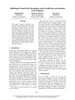
from the user who is interacting with the device. The kinematic model of the skeleton
is a full skeleton model of the body consisting in 15 joints as shown in Figure2. The
algorithms provide the 3D positions and orientations of every joint and update them at
the rate of 30fps. Additionally they also provide the confidence of these measures are
able to track up to four simultaneous skeletons.
Figure 3. OpenNI’s kinematic model of the human body
9
Head
Neck
Right Shoulder
Right Elbow
Right Hand
Right Hip
Right Knee
Right Foot
Torsor
Left Shoulder
Left Elbow
Left Hand
Left Knee
Left Foot
Left Hip
Other researches using MS Kinect for human pose estimation have also been
addressed. In [7], J. Charles et al. proposed method for learning and recognizing 2D
articulated human pose models from a single depth image obtained from Microsoft
Kinect. Although the pose estimation is substantially recognized, the 2d presentation
of articulated human pose models makes the human activity recognition process more
difficult in comparing with 3D presentation of OpenNI. In [14], L. M. Adolfo et al.
presented a method for upper body pose estimation with online initialization of pose
and anthropometric profile. A likelihood evaluation is implemented to allow the
system to run in real-time. Although the method in [14] has a better performance, in
comparing with OpenNI, in limb self occlusion cases, only upper presentation of body
pose is suitable for small range of recognition applications. From these reasons, we
choose OpenNI to preprocess the depth images from MS Kinect to obtain the human
skeleton models.
2.2Traffic gesture recognition
[6] presents an approach to recognize traffic gesture in Chinese traffic. The Chinese
traffic police gesture system is defined and regulated by Chinese Ministry of Public
Security. Figure 4 shows 2 in 10 types of gesture.
Figure 4. Chinese traffic gestures
The idea of this recognition system is based on rotation joint angle. It can be seen
from Figure 4 that these gestures need upper and lower arms keep certain angles to the
vertical direction by rotating around shoulder or elbow joints, so the rotation joint
angles are used to recognize gestures which makes it easy to add a new gesture
without changing the existing angles. Since the gestures may not be performed
perfectly in real situation, we set the angles in certain rangenot a fixed value. Let θ
i
(
i=1 4) θ
i
denotes the rotation angle related to each arm for the gestures, information
about is provided in Table 3.
10
Gesture
Left upper
arm (θ
1
)
Left lower arm (θ
2
)
Right upper
arm (θ
3
)
Right lower arm (θ
4
)
Stop signal [0
0
, 10
0
] [θ
2
-10
0
, θ
2
+10
0
] [170
0
, 180
0
] [θ
4
-10
0
, θ
4
+10
0
]
Move
straight
(leftward)
[80
0
, 110
0
] [θ
2
-30
0
, θ
2
+30
0
] [100
0
, 175
0
] [θ
4
+30
0
, θ
4
+160
0
]
Move
straight
(rightward)
[100
0
, 175
0
] [θ
2
+30
0
,θ
2
+160
0
] [80
0
, 110
0
] [θ
4
-30
0
, θ
4
+30
0
]
Table 3.Rotation joint angles related each arm
Even thought this approach takes some advantages such as no special clothing
requirement, unperfected-performed gesture recognition and efficient running with
video;it is obvious to be seen this work must be work on RGB image which includes
lot of noise.Based-on reflect clothes of traffic police is also a limitation to detect
police.
2.3 Real-time human pose recognition in parts from single depth images
In [8], the researchers propose a new method to quickly and accurately predict 3D
positions of body joints from a single depth image, using no temporal information.
They take an object recognition approach, designing an intermediate body parts
representation that maps the difficult pose estimation problem into a simpler per-pixel
classification problem. Their large and highly varied training dataset allows the
classifier to estimate body parts invariant to pose, body shape, clothing, etc. Finally
they generate confidence-scored 3D proposals of several body joints by reprojecting
the classification result and finding local models.
2.4 Hand tracking and gesture recognition
Cristina Manresa et al [4](Hand tracking and gesture recognition) works aims at the
control of videogame based on hand gesture recognition. They propose a new
algorithm to track and recognize hand gestures for interacting with videogame. This
algorithm is based on three steps: hand segmentation, hand tracking and gesture
recognition from hand gesture. For the hand segmentation step we use the color cue
due to the characteristic color values of human skin, its invariant properties and its
computational simplicity. To prevent errors from hand segmentation we add the hand
tracking as a second step. Tracking is performed assuming a constant velocity model
and using a pixel labeling approach. From the tracking process we extract several
11
hand features that are fed into a finite state classifier which identifies the hand
configuration. The hand can be classified into one of the four gesture classes or one of
the four different movement directions.
3. Problem solution
3.1 Proposal approach
3.1.1 Feature vector selection
3.1.1.1 Synthetic data collection
The human body is capable of an enormous range of poses which are difficult to
simulate. Instead, we capture a database from a group of persons. As we mentioned
before, our work in this paper focus on 3 main pose of traffic police which illustrated
in Figure 1 and for the experiments in this paper, we separate each pose into 2 cases
with left hand and right hand, therefore we have 6 classes of human pose.
Since the classifier uses no temporal information, we are interested only in static
poses and not motion. For each person we record each pose about 1000 frames with
variation in rotation about the vertical axis, mirroring left-right, scene position. With
Opening and depth image, we can get the coordinates of all 15 skeletal joints. From
these joints, we promote the feature vector for each frames and use this vector for
training data. Training data will have about 30000 vectors and each vector is classified
by its pose tag.
3.1.1.2 Feature vector selection
We introduce a class of angle value features expressing geometric relations
[12]between certain body points of a gesture. As an example of this kind of features,
consider the test whether the left arm raises straight up or to the left by calculation of
angle between left arm and shoulder. Such geometric featuresare very robust to spatial
variations and allow the identificationof logically corresponding events in similar
motions.In particular, (user-specified) combinations of such qualitativefeatures
become a powerful tool in describing and specifyinggesture. In our approach, we
define a kind of geometric feature describing geometric relationbetween specified
points of the kinematic chain for some fixed, isolated gestures. To the end, we need
the notion of a feature which we describe mathematically as a function
. Obviously, any attribute of feature functions is a function which
expresses the relative position between body parts by calculating angle between them.
12
For classification purpose, a fixed size feature vector which is invariant to translation,
rotation, and scaling must be extracted for each skeleton. In in research, we propose
the relative angle between joints for feature vector attributes due to these information
invariant in real-space coordinate system.
Research [17] builds a 3D human model from depth image and extracts feature vector
based on the angle of body part and coordinate axes. Our work simplifies 3D human
model to a skeletal model – that constructed by a set of points (each joint is
represented a body part). In our approach, we use Kinect with open source library
OpenNI for data collection. This library enables users to capture depth image, detect
human and recognize human as well. Moreover, human body parts are also segmented
and represented by a point in the center of respective part in depth map. Therefore, 3D
human model is displayed in human skeletal model. There are 15 body parts which
construct human skeleton model are denoted by 15 joints:
o Upper body: head, neck, torso,
o Upper left part: left shoulder, left elbow, left hand
o Upper right part: right shoulder, right elbow, right hand
o Lower left part: left hip, left knee, left foot
o Lower right part: right hip, right knee, right foot
We now consider a special class of geometrically meaningful feature functions. As an
example, a geometric feature may express whether the arm raises to the left or to the
front for a fixed gesture. More generally, let A is the degree of angle between left arm
and horizontal axis based on left to right shoulder.
A
Based on the description of 6 traffic gestures, only upper body parts are moving the
most. From this we obtain a feature function for any two parts
of upper human body by defining:
where is one part of upper body.
As can be seen from Fig.3, the arm, the hand, the shoulder and backbone (constructed
by neck and torso) illustrates different angles between pairs of them which vary six
gestures. In our approach, the feature vector includes ten attributes. Ten attributes are
13
constructed by angle of 2 vectors (each one is defined by start point and end point
respectively):
14
- (left elbow, left shoulder) and (left elbow, left hand)
- (right elbow, right shoulder) and (right elbow, right hand)
- (left shoulder, neck) and (left shoulder, left elbow)
- (right shoulder, neck) and (right shoulder, right elbow)
- (neck, head) and (neck, left shoulder)
- (neck, head) and (neck, right shoulder)
- (left shoulder, left hand) and (head, torso)
- (right shoulder, right hand) and (head, torso)
- (left shoulder, left hand) and (left shoulder, right shoulder)
- (right shoulder, right hand) and (left shoulder, right shoulder)
In addition, these joints includes three coordinate values which belongs to x axis
(vertical axis), y axis (horizontal axis) and z axis – known as the depth value of this
point (the distance from Kinect to current point). Angle between two vectors
and :
The concept of such geometric features is simple but powerful, as we will illustrate by
describe the below example. Each attributes of feature function which expresses the
relative angle of two body parts is measured by two vectors, each vector is constructed
by two body joints of human skeletal model.
15
For gesture: “left hand raises to the left”:
Angle of Ideal value
of angle
Real value
of angle
Body part 1 Body part 2
(left elbow, left shoulder) (left elbow, left hand) 3.141 (≈ π
rad)
2.986 (rad)
(right elbow, right
shoulder)
(right elbow, right hand) 3.141 (π) 2.782
(left shoulder, neck) (left shoulder, left elbow) 3.141 (π) 3.051
(right shoulder, neck) (right shoulder, right
elbow)
1.570 (π/2) 1.828
(neck, head) (neck, left shoulder) 1.570 (π/2) 1.593
(neck, head) (neck, right shoulder) 1.570 (π/2) 1.548
(left shoulder, left hand) (head, torso) 1.570 (π/2) 1.619
(right shoulder, right
hand)
(head, torso) 0 0.254
(left shoulder, left hand) (left shoulder, right
shoulder)
3.141 (π) 3.011
(right shoulder, right
hand)
(left shoulder, right
shoulder)
1.570 (π/2) 1.784
Table 4. Rotation joint angle between two body parts
On the other hand, the feature F is invariant under global orientation and position, the
size of skeleton and various local spatial deviations such as vertical movements of the
shoulder or neck. Of course, F leaves any upper body movements unconsidered. In
general, feature functions define purely in terms of geometric entities that are
expressible by joint coordinates are invariant under global transforms such
asEuclidean motions and scaling.
3.1.2 Training and classification
3.1.2.1 Classifier: Kmeans
Firstly, we briefly describe the direct k-means algorithm. The number of clusters k is
assumed to be fixed in k-means clustering. Let the prototypes
be initialized to one of the input patterns
. Therefore,
16
Figure 5 shows a high level description of the direct kmeans clustering algorithm.
is the cluster whose value is a disjoint subset of input patterns. The quality
of the clustering is determined by the following error function:
Function Direct-k-means()
Initialize k prototypes such that
Each cluster is associated with prototype
Repeat
for each input vector , where , do
Assign to the cluster with nearest prototype
(i.e.
)
for each cluster , where do
Update the prototype to be the centroid of all samples
currently in , so that
Compute the function:
Until does not change significantly or cluster memebership no longer
changes
Figure 5. Direct k-means clustering algorithm
17
The appropriate choice of is problem and domain dependentand generally a user
triesseveral values of k.Assumingthat there are patterns, each of dimension ,
thecomputational cost of a direct k-means algorithm per iteration(of the repeat loop)
can bedecomposed into three parts:
1. The time required for the first for loop in Figure 5is
2. The time required for calculating the centroids (secondfor loop in Figure 5) is
3. The time required for calculating the error function is .
The number of iterations required can vary in a widerange from a few to several
thousanddepending on thenumber of patterns, number of clusters, and the input
datadistribution.Thus, a direct implementation of the k-meansmethod can be
computationally very intensive.This is especiallytrue for typical data mining
applications with largenumber of pattern vectors.
There are two main approaches described in the literaturewhich can be used to
reducethe overall computationalrequirements of the k-means clustering method
especiallyfor the distance calculations:
1. Use the information from the previous iteration toreduce the number
ofdistance calculations. PCLUSTERis a k-means-based clustering algorithmwhich
exploits the fact that the change of the assignmentof patterns to clusters are relatively
few after thefirst few iterations. It uses a heuristic which determinesif the closest
prototype of a pattern E has beenchanged or not by using a simple check. If the
assignmenthas not changed, no further distancecalculationsare required. It also uses
the fact that the movement ofthe cluster centroids is small for consecutive
iterations(especially after a few iterations).
2. Organize the prototype vectors in a suitable data structure so that finding the
closest prototype for a givenpattern becomes more efficient. This problemreduces to
finding the nearest neighbor problemfor a given pattern in the prototype space. The
number of distance calculations using this approach is proportionalto
per iteration. For many applicationssuch as vector quantization, the
prototype vectorsare fixed. This allows for construction of optimal datastructures to
find the closest vector for a given inputtest pattern . However, these optimizations are
18
notapplicable to the k-means algorithm as the prototypevectors will change
dynamically. Further, it is not clearhow these optimizations can be used to reduce the
timefor calculation of the error function (which becomes asubstantial component after
reduction in the number ofdistance calculations).[2]
The main idea of K-mean Clustering [15] is to define 6 initial centroids, namely, the
number of cluster desired which is the number of traffic gestures. The next step is to
take each point belonging to a given data set and associate it to the nearest centroid by
minimum Euclid distance calculation, and each collection of points assigned to a
centroid is a cluster. At this point we need to re-calculate 6 new centroids of the
clusters resulted by calculating average value. After we have 6 new centroids, a new
binding has to be done between the same data set points and the nearest new centroid.
A loop has been generated. As a result of this loop we may notice that the 6 centroids
change their location step by step until no more changes are done. In other words
centroids do not move any more, and the centroids remain the same.
For avoidance of irrelevant gestures in real-time recognition, this method adds
a threshold value of distance between a input vector and a centroid. Only the distance
smaller than threshold value determines the current gesture is classified exactly. Our
experiment shows that 0.8 is a good threshold to classify the respective gesture.
3.1.2.2 Support vector machine (SVM)
Support vector machines (SVMs), introduced by Vapnik and his collaborators, were
originally formulated for binary-classification problems. Later, SVMs were extended
to regression problems, and the resulting formulations are similar to ridge re-gression.
The general framework of support vector learning includes four main components:
- Regularized linear learning models (such as classification and regression)
- Theoretical bounds
- Convex duality and the associated dual-kernel representation
- Sparseness of the dual-kernel representation
The differences of SVMs with other learning methods is unique combination of these
concepts. This make SVMs and related kernel-based learning methods special and
interesting. (Ref: Tong Zhang. “An Introduction to Support Vector Machines and
Other Kernel-Based Learning Methods: A Review”, AI Magazine vol 22 Number 2,
2001.
The primal SVM formulation
19
In formal terms, the parameter θ that SVMs learn consists solely of a vector ,
representing the normal to the separating hyperplane with maximum margin. In the
rest of this document, we will use w in place of θ whenever we refer to a problem for
which θ = ( ).
There are two ways of treating the SVM problem. The classical method is the hard
margin SVM, which assumes that the dataset is linearly separable: hence, every point
must be correctly classified by the maximum margin hyper plane. The soft margin
SVM allows for some points to be misclassified, but penalizes these points
appropriately. The latter is more useful in practical settings where data is unlikely to
be perfectly separable (e.g. due to noise), and so we focus on this version. It can be
represented with the following optimization problem.
THEOREM 1. Given a training set {( , )}
i
n
=1 of training examples where
{ 1} , the hyperplane parameterized by normal vector that balances the
goal of separating the data and maximizing margin can be found by solving the
following optimization problem:
2
+
where 0 is called regularization parameter.
As a note on terminology: instead of using a regularization parameter that scales
2
, we can use a misclassification parameter that scales the empirical loss
term. The two are related by .
The dual formulation and kernels
The above analysis assumed that we were seeking a hyper plane in the same space as
the dataset, that is, a linear classifier. SVMs can be used as nonlinear classifiers using
the classic kernel trick. The idea is to embed the data points into some higher
20
dimensional space using some mapping : , and to seek a
linear classifier in . This will of course be nonlinear in the original space .
The kernel trick allows us to make the mapping implicit,
by defining the kernel matrix K, where K
ij
= ( ). ( ). If in the
original space we only employ dot-products to solve the learning problem,
we can seamlessly transfer to a high
dimensional space by simply replacing these dot-products by K
ij
. This suggests that
we can use any kernel matrix K that defines a valid dot-product in a high dimensional
space, without knowing precisely what the high dimensional mapping is!
Mercer’s theorem
tells us that any positive semi-definite matrix is a valid kernel matrix.
For SVMs, the primal problem we described in the previous section is its most natural
form, because it captures exactly the quantity we wish to minimize. When moving to
kernels with SVMs, however, it is standard to work with the dual optimization
problem. The reason is that the dual version uses explicit dot-products, as we show
below.
THEOREM 2. The dual formulation of the SVM optimization problem in Theorem 1
equation is
subject to .
Since we have an explicit dot-product, using kernel is simple: we replace
by K
ij
, giving the dual problem:
21
subject to .
Several practical applications of SVMs use nonlinear kernels, such as the polynomial
and RBF kernel. However, in applications like text classification, linear SVMs are still
used, because it has been observed that many text classification problems are linearly
separable.
Support Vector
The dual SVM problem lets us define the important concept of support vectors that
give SVMs their name. These vectors are the training points which are not classified
with confidence; that is, they are either misclassified, or are correctly classified but
fall inside the margin region. Equivalently, they are the examples whose
corresponding values are non-zero. Recalling the representer theorem from the
previous section, this tells us that the optimal weight vector is a linear
combination of the support vectors. Therefore, the support vectors are the “essential”
training points, and the goal of training is to discover them.
The number of support vectors also characterizes the complexity of the
learning task: if is small, then that suggests that only a few examples are
important, and that we can disregard many examples without any loss in accuracy.
However, if is large, then nearly every example is important for
accuracy.This suggests that asymptotically, all points are critical for training! While
this seemingly gives an bound on training time, we note that this is only to
solve the SVM problem exactly.
Loss Function
We make a brief comment about the choice of loss function in SVMs. The standard
definition of SVMs uses
22
, as we have done; this is known as the hinge-loss.
This penalizes errors linearly, but has the disadvantage that it is not differentiable
everywhere. A common variant of the classical SVM definition is to instead use the
square-loss, ,
which is differentiable everywhere. An intermediate solution is the Huber loss, which
is linear for , but quadratic for
, and hence also differentiable everywhere. All these loss functions
are convex, which means that it is easy to optimize with them, and they also upper-
bound the 0-1 loss function. This means that minimizing these losses also makes
bounds the misclassification error of our classifier.
In practice, the differentiability of the square and Huber loss is appealing, and indeed
these losses are sometimes used for this reason. Theoretically however, it has been
shown that using the hinge-loss, SVMs approach the optimal classifier (also called the
Bayes classifier), whereas the square and higher order losses approach only a
distribution whose sign gives the optimal classifier . Having said this, it is not clear
whether there is a discernible practical difference in accuracy when one does not use
the hinge-loss.
It is straightforward to incorporate different losses into the primal version of the SVM
problem (Equation in Theorem 1): treating
as a special case of a loss function , we
can plug in the square or Huber loss and get a similar optimization problem. It is not
as obvious how the change in loss function affects the dual problem. The dual
problem for the hinge- and square-loss can be expressed as
subject to
where for some diagonal matrix
D and U is some constant. The values of D ,U depend on the loss function: for
23
hinge-loss, and . For square-loss
[1]
LibSVM[25]
There are many library or application for support vector classification with many
strong points but for simplicity, we use LibSVM. LibSVM is an integrated software
for support vector classification, regression and distribution estimation. It supports
multi-class classification. Since version 2.8, it implements an SMO-type algorithm.
LibSVM provides a simple interface where users can easily link it with their own
programs. LibSVM include following main features:
- Different SVM formulations
- Efficient multi-class classification
- Cross validation for model selection
- Probability estimates
- Various kernels (including precomputed kernel matrix)
- Weighted SVM for unbalanced data
- Both C++ and Java sources
- GUI demonstrating SVM classification and regression
- Python, R, MATLAB, Perl, Ruby, Weka, Common LISP, CLISP, Haskell,
LabVIEW, and PHPinterfaces. C# .NET code and CUDA extension is
available.
It's also included in some data mining environments: RapidMiner and PCP.
- Automatic model selection which can generate contour of cross validation
accuracy.
24
Training and predicting by LibSVM
In our research, SVMs uses the training data to generate a SVM model with six labels
linked with six gestured. In real-time process, data from each frame is transformed to
SVMs data. After that, we used SVMs prediction function to compare this data with
SVMs training model and the result will be the gesture has most similar with this
action. All of the SVMs processing (training and predicting) has be done by an open
source library – libSVM.
3.2 Experiment
To collect training data samples, we capture a traffic gesture database for a group of
five persons. Each person performs a traffic gesture at different location and angle to
Kinect sensor. For each traffic gesture of a performing person, we record about 1000
frames of depth images. Then, the coordinates of all 15 skeletal joints for each frame
is calculated and stored in the traffic gesture database. Totally, the number of training
vectors in our traffic gesture database is 30 509 and each vector is labeled by its the
gesture number.
The Weka tool [23] is used to train and test human pose recognition accuracy with
Kmeans clustering and C-SVMs classifier with C=1.0 and kernel RBF. The data set
includes 30509 samples labeled by six defined gestures. The test mode is 10-fold-
cross-validation which means that 1/10 samples are retained as the validation data for
testing the model, and the remaining 9/10 samples are used as training data. Table
5shows the experimental results (in percentage) which are true positive (TP) rate, false
positive (FP), and precision for the two classifiers Kmeans and C-SVMs. TP rate is
the proportion of samples which were classified as gesture x, among all examples
which is truly labeled as gesture x. False positive (FP) rate is the proportion of
examples which were classified as gesture x, but labeled as a different gesture, among
all examples which are not labeled as gesture x. Precision is the proportion of the
examples which is truly labeled as x among all those which were classified as gesture
x. The experiments were done on Windows PC of Pentium 4, and 1GB RAM.
25