HỆ THỐNG ĐIỀU KHIỂN THẮNG XE TRÊN NISSAN VERSA SEDAN ĐỜI 2012
Bạn đang xem bản rút gọn của tài liệu. Xem và tải ngay bản đầy đủ của tài liệu tại đây (2.59 MB, 110 trang )
BRC-1
BRAKES
C
D
E
G
H
I
J
K
L
M
SECTION BRC
A
B
BRC
N
O
P
CONTENTS
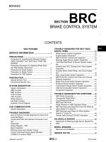
BRAKE CONTROL SYSTEM
VDC/TCS/ABS
PRECAUTION
4
PRECAUTIONS 4
Precaution for Supplemental Restraint System
(SRS) "AIR BAG" and "SEAT BELT PRE-TEN-
SIONER"
4
Precaution for Procedure without Cowl Top Cover 4
Precaution for Brake System 4
Precaution for Brake Control 5
Precaution for CAN System 5
PREPARATION 7
PREPARATION 7
Special Service Tool 7
Commercial Service Tool 7
SYSTEM DESCRIPTION 8
COMPONENT PARTS 8
Component Parts Location 8
Component Description 9
ABS Actuator and Electric Unit (Control Unit) 9
Wheel Sensor and Sensor Rotor 10
Stop Lamp Switch 10
Steering Angle Sensor 10
VDC OFF Switch 10
Brake Fluid Level Switch 11
Parking Brake Switch 11
SYSTEM 12
VDC/TCS/ABS 12
VDC/TCS/ABS : System Diagram 12
VDC/TCS/ABS : System Description 12
VDC/TCS/ABS : VDC Function 23
VDC/TCS/ABS : TCS Function 25
VDC/TCS/ABS : ABS Function 27
VDC/TCS/ABS : EBD Function 28
VDC/TCS/ABS : Fail-safe 29
DIAGNOSIS SYSTEM [ABS ACTUATOR
AND ELECTRIC UNIT (CONTROL UNIT)]
32
CONSULT Function (ABS) 32
ECU DIAGNOSIS INFORMATION 36
ABS ACTUATOR AND ELECTRIC UNIT
(CONTROL UNIT)
36
Reference Value 36
Fail-safe 39
DTC Inspection Priority Chart 42
DTC Index 42
WIRING DIAGRAM 44
BRAKE CONTROL SYSTEM 44
Wiring Diagram 44
BASIC INSPECTION 51
DIAGNOSIS AND REPAIR WORK FLOW 51
Work Flow 51
Diagnostic Work Sheet 52
ADDITIONAL SERVICE WHEN REPLACING
ABS ACTUATOR AND ELECTRIC UNIT
(CONTROL UNIT)
53
Description 53
Work Procedure 53
ADJUSTMENT OF STEERING ANGLE SEN-
SOR NEUTRAL POSITION
54
Description 54
Work Procedure 54
DTC/CIRCUIT DIAGNOSIS 56
C1101, C1102, C1103, C1104 WHEEL SEN-
SOR
56
DTC Logic 56
Diagnosis Procedure 56
Revision: July 2011 2012 Versa Sedan
BRC-2
C1105, C1106, C1107, C1108 WHEEL SEN-
SOR
58
DTC Logic 58
Diagnosis Procedure 58
C1109 POWER AND GROUND SYSTEM 60
DTC Logic 60
Diagnosis Procedure 60
C1110, C1153, C1170 ABS ACTUATOR AND
ELECTRIC UNIT (CONTROL UNIT)
62
DTC Logic 62
Diagnosis Procedure 62
C1111 PUMP MOTOR 63
DTC Logic 63
Diagnosis Procedure 63
C1115 ABS SENSOR [ABNORMAL SIGNAL] 65
DTC Logic 65
Diagnosis Procedure 65
C1116 STOP LAMP SWITCH 67
DTC Logic 67
Diagnosis Procedure 67
C1120, C1122, C1124, C1126 ABS IN VALVE
SYSTEM
69
DTC Logic 69
Diagnosis Procedure 69
C1121, C1123, C1125, C1127 ABS OUT
VALVE SYSTEM
71
DTC Logic 71
Diagnosis Procedure 71
C1130 ENGINE SIGNAL 73
DTC Logic 73
Diagnosis Procedure 73
C1140 ACTUATOR RELAY SYSTEM 74
DTC Logic 74
Diagnosis Procedure 74
C1142 PRESS SENSOR 76
DTC Logic 76
Diagnosis Procedure 76
C1143 STEERING ANGLE SENSOR 77
DTC Logic 77
Diagnosis Procedure 77
C1144 INCOMPLETE STEERING ANGLE
SENSOR ADJUSTMENT
79
DTC Logic 79
Diagnosis Procedure 79
C1145, C1146 YAW RATE/SIDE/DECEL G
SENSOR
80
DTC Logic 80
Diagnosis Procedure 80
C1155 BR FLUID LEVEL LOW 81
DTC Logic 81
Diagnosis Procedure 81
Component Inspection 82
C1164, C1165, C1166, C1167 CV/SV SYS-
TEM
83
DTC Logic 83
Diagnosis Procedure 83
U1000 CAN COMM CIRCUIT 85
DTC Logic 85
Diagnosis Procedure 85
U1002 SYSTEM COMM (CAN) 86
DTC Logic 86
Diagnosis Procedure 86
PARKING BRAKE SWITCH 87
Component Function Check 87
Diagnosis Procedure 87
Component Inspection 88
VDC OFF SWITCH 89
Component Function Check 89
Diagnosis Procedure 89
Component Inspection 90
ABS WARNING LAMP 91
Component Function Check 91
Diagnosis Procedure 91
BRAKE WARNING LAMP 92
Component Function Check 92
Diagnosis Procedure 92
VDC OFF INDICATOR LAMP 93
Component Function Check 93
Diagnosis Procedure 93
SLIP INDICATOR LAMP 94
Component Function Check 94
Diagnosis Procedure 94
SYMPTOM DIAGNOSIS 95
VDC/TCS/ABS 95
Symptom Table 95
EXCESSIVE ABS FUNCTION OPERATION
FREQUENCY
96
Diagnosis Procedure 96
UNEXPECTED PEDAL REACTION 97
Diagnosis Procedure 97
THE BRAKING DISTANCE IS LONG 98
Diagnosis Procedure 98
ABS FUNCTION DOES NOT OPERATE 99
Diagnosis Procedure 99
Revision: July 2011 2012 Versa Sedan
BRC-3
C
D
E
G
H
I
J
K
L
M
A
B
BRC
N
O
P
PEDAL VIBRATION OR ABS OPERATION
SOUND OCCURS
100
Diagnosis Procedure 100
VEHICLE JERKS DURING VDC/TCS/ABS
CONTROL
101
Diagnosis Procedure 101
NORMAL OPERATING CONDITION 102
Description 102
REMOVAL AND INSTALLATION 103
WHEEL SENSOR 103
FRONT WHEEL SENSOR 103
FRONT WHEEL SENSOR : Exploded View 103
FRONT WHEEL SENSOR : Removal and Instal-
lation
103
REAR WHEEL SENSOR 104
REAR WHEEL SENSOR : Exploded View 104
REAR WHEEL SENSOR : Removal and Installa-
tion
104
SENSOR ROTOR 106
FRONT SENSOR ROTOR 106
FRONT SENSOR ROTOR : Removal and Instal-
lation
106
REAR SENSOR ROTOR 106
REAR SENSOR ROTOR : Removal and Installa-
tion
106
ABS ACTUATOR AND ELECTRIC UNIT
(CONTROL UNIT)
107
Exploded View 107
Removal and Installation 107
VDC OFF SWITCH 109
Removal and Installation 109
STEERING ANGLE SENSOR 110
Removal and Installation 110
Revision: July 2011 2012 Versa Sedan
BRC-4
< PRECAUTION >
[VDC/TCS/ABS]
PRECAUTIONS
PRECAUTION
PRECAUTIONS
Precaution for Supplemental Restraint System (SRS) "AIR BAG" and "SEAT BELT
PRE-TENSIONER"
INFOID:0000000007673949
The Supplemental Restraint System such as “AIR BAG” and “SEAT BELT PRE-TENSIONER”, used along
with a front seat belt, helps to reduce the risk or severity of injury to the driver and front passenger for certain
types of collision. This system includes seat belt switch inputs and dual stage front air bag modules. The SRS
system uses the seat belt switches to determine the front air bag deployment, and may only deploy one front
air bag, depending on the severity of a collision and whether the front occupants are belted or unbelted.
Information necessary to service the system safely is included in the SR and SB section of this Service Man-
ual.
WARNING:
• To avoid rendering the SRS inoperative, which could increase the risk of personal injury or death in
the event of a collision which would result in air bag inflation, all maintenance must be performed by
an authorized NISSAN/INFINITI dealer.
• Improper maintenance, including incorrect removal and installation of the SRS, can lead to personal
injury caused by unintentional activation of the system. For removal of Spiral Cable and Air Bag
Module, see the SR section.
• Do not use electrical test equipment on any circuit related to the SRS unless instructed to in this
Service Manual. SRS wiring harnesses can be identified by yellow and/or orange harnesses or har-
ness connectors.
PRECAUTIONS WHEN USING POWER TOOLS (AIR OR ELECTRIC) AND HAMMERS
WARNING:
• When working near the Airbag Diagnosis Sensor Unit or other Airbag System sensors with the Igni-
tion ON or engine running, DO NOT use air or electric power tools or strike near the sensor(s) with a
hammer. Heavy vibration could activate the sensor(s) and deploy the air bag(s), possibly causing
serious injury.
• When using air or electric power tools or hammers, always switch the Ignition OFF, disconnect the
battery, and wait at least 3 minutes before performing any service.
Precaution for Procedure without Cowl Top Cover INFOID:0000000007207972
When performing the procedure after removing cowl top cover, cover
the lower end of windshield with urethane, etc to prevent damage to
windshield.
Precaution for Brake System INFOID:0000000007673950
CAUTION:
• Refer to MA-12, "
Fluids and Lubricants" for recommended brake fluid.
• Never reuse drained brake fluid.
• Be careful not to splash brake fluid on painted areas; it may cause paint damage. If brake fluid is
splashed on painted areas, wash it away with water immediately.
• To clean or wash all parts of master cylinder and disc brake caliper, use clean brake fluid.
• Never use mineral oils such as gasoline or kerosene. They will ruin rubber parts of the hydraulic sys-
tem.
PIIB3706J
Revision: July 2011 2012 Versa Sedan
PRECAUTIONS
BRC-5
< PRECAUTION >
[VDC/TCS/ABS]
C
D
E
G
H
I
J
K
L
M
A
B
BRC
N
O
P
• Use flare nut wrench when removing and installing brake
tube.
• If a brake fluid leak is found, the part must be disassembled
without fail. Then it has to be replaced with a new one if a
defect exists.
• Turn the ignition switch OFF and remove the connector of the
ABS actuator and electric unit (control unit) or the battery ter-
minal before performing the work.
• Always torque brake lines when installing.
Precaution for Brake Control INFOID:0000000007673951
• During ABS operation, the brake pedal may vibrate lightly and a mechanical noise may be heard. This is
normal.
• Just after starting vehicle, the brake pedal may vibrate or a motor operating noise may be heard from engine
compartment. This is a normal status of operation check.
• Stopping distance may be longer than that of vehicles without ABS when vehicle drives on rough, gravel, or
snow-covered (fresh, deep snow) roads.
• When an error is indicated by ABS or another warning lamp, collect all necessary information from customer
(what symptoms are present under what conditions) and check for simple causes before starting diagnosis.
Besides electrical system inspection, check booster operation, brake fluid level, and fluid leaks.
• If incorrect tire sizes or types are installed on the vehicle or brake pads are not Genuine NISSAN parts, stop-
ping distance or steering stability may deteriorate.
• If there is a radio, antenna or related wiring near control module, ABS function may have a malfunction or
error.
• If aftermarket parts (car stereo, CD player, etc.) have been installed, check for incidents such as harness
pinches, open circuits or improper wiring.
• If the following components are replaced with non-genuine components or modified, the VDC OFF indicator
lamp and SLIP indicator lamp may turn on or the VDC system may not operate properly. Components
related to suspension (shock absorbers, struts, springs, bushings, etc.), tires, wheels (exclude specified
size), components related to brake system (pads, rotors, calipers, etc.), components related to engine (muf-
fler, ECM, etc.), components related to body reinforcement (roll bar, tower bar, etc.).
• Driving with broken or excessively worn suspension components, tires or brake system components may
cause the VDC OFF indicator lamp and the SLIP indicator lamp to turn on, and the VDC system may not
operate properly.
• When the TCS or VDC is activated by sudden acceleration or sudden turn, some noise may occur. The
noise is a result of the normal operation of the TCS and VDC.
• When driving on roads which have extreme slopes (such as mountainous roads) or high banks (such as
sharp curves on a freeway), the VDC may not operate normally, or the VDC warning lamp and the SLIP indi-
cator lamp may turn on. This is not a problem if normal operation can be resumed after restarting the engine.
• Sudden turns (such as spin turns, acceleration turns), drifting, etc. with VDC turned off may cause the yaw
rate/side/decel G sensor to indicate a problem. This is not a problem if normal operation can be resumed
after restarting the engine.
Precaution for CAN System INFOID:0000000007673952
• Do not apply voltage of 7.0V or higher to terminal to be measured.
• Maximum open terminal voltage of tester in use must be less than 7.0V.
• Before checking harnesses, turn ignition switch OFF and disconnect battery negative cable.
SBR686C
Revision: July 2011 2012 Versa Sedan
BRC-6
< PRECAUTION >
[VDC/TCS/ABS]
PRECAUTIONS
• Area to be repaired must be soldered and wrapped with tape.
Make sure that fraying of twisted wire is within 110 mm (4.33 in).
• Do not make a bypass connection to repaired area. (If the circuit is
bypassed, characteristics of twisted wire will be lost.)
PKIA0306E
PKIA0307E
Revision: July 2011 2012 Versa Sedan
PREPARATION
BRC-7
< PREPARATION >
[VDC/TCS/ABS]
C
D
E
G
H
I
J
K
L
M
A
B
BRC
N
O
P
PREPARATION
PREPARATION
Special Service Tool INFOID:0000000007630965
The actual shapes of Kent-Moore tools may differ from those of special service tools illustrated here.
Commercial Service Tool INFOID:0000000007630966
Tool number
(Kent-Moore No.)
Tool name
Description
—
(J-45741)
ABS active wheel sensor tester
Checking operation of ABS active wheel sen-
sor
WFIA0101E
Tool name Description
1. Flare nut crowfoot
2. Torque wrench
Removing and installing brake piping
a: 10mm (0.39 in)/12mm (0.47 in)
S-NT360
Revision: July 2011 2012 Versa Sedan
BRC-8
< SYSTEM DESCRIPTION >
[VDC/TCS/ABS]
COMPONENT PARTS
SYSTEM DESCRIPTION
COMPONENT PARTS
Component Parts Location INFOID:0000000007616444
ALFIA0213ZZ
Revision: July 2011 2012 Versa Sedan
COMPONENT PARTS
BRC-9
< SYSTEM DESCRIPTION >
[VDC/TCS/ABS]
C
D
E
G
H
I
J
K
L
M
A
B
BRC
N
O
P
Component Description INFOID:0000000007616445
ABS Actuator and Electric Unit (Control Unit) INFOID:0000000007616446
Electric unit (control unit) is integrated with actuator and comprehensively controls VDC function, TCS func-
tion, ABS function and EBD function.
ELECTRIC UNIT (CONTROL UNIT)
• Brake fluid pressure is controlled according to signals from each sensor.
• If malfunction is detected, the system enters fail-safe mode.
ACTUATOR
The following components are integrated with ABS actuator.
Pump
Returns the brake fluid reserved in reservoir to master cylinder by reducing pressure.
Motor
Activates the pump according to signals from ABS actuator and electric unit (control unit).
Motor Relay
Operates the motor ON/OFF according to signals from ABS actuator and electric unit (control unit).
Actuator Relay (Main Relay)
Operates each valve ON/OFF according to signals from ABS actuator and electric unit (control unit).
ABS IN Valve
Switches the fluid pressure line to increase or hold according to signals from control unit.
ABS OUT Valve
1 ABS actuator and electric unit (con-
trol unit)
2 IPDM E/R 3 Brake fluid level switch
(view with IPDM E/R removed)
4 Front wheel sensor 5 Rear wheel sensor 6 VDC OFF switch
7 Steering angle sensor
(view with steering wheel and spiral
cable removed)
8 Stop lamp switch 9 Parking brake switch
(view with console removed)
10 Combination meter (type B) 11 Combination meter (type A)
Component Reference/Function
ABS actuator and electric unit (control unit) BRC-9, "
ABS Actuator and Electric Unit (Control Unit)"
Wheel sensor BRC-10, "Wheel Sensor and Sensor Rotor"
Stop lamp switch BRC-10, "Stop Lamp Switch"
Steering angle sensor BRC-10, "Steering Angle Sensor"
VDC OFF switch BRC-10, "VDC OFF Switch"
Brake fluid level switch BRC-11, "Brake Fluid Level Switch"
Parking brake switch BRC-11, "Parking Brake Switch"
ABS warning lamp
BRC-12, "
VDC/TCS/ABS : System Description"
Brake warning lamp
VDC OFF indicator lamp
SLIP indicator lamp
ECM
Transmits the following signals to ABS actuator and electric unit (control unit) via CAN
communication.
• Accelerator pedal position signal
• Engine speed signal
• Target throttle position signal
TCM
Transmits the current gear position signal to ABS actuator and electric unit (control
unit) via CAN communication.
Revision: July 2011 2012 Versa Sedan
BRC-10
< SYSTEM DESCRIPTION >
[VDC/TCS/ABS]
COMPONENT PARTS
Switches the fluid pressure line to increase, hold or decrease according to signals from control unit.
Cut Valve 1, Cut Valve 2
Shuts off the ordinary brake line from master cylinder, when VDC function and TCS function are activated.
Suction Valve 1, Suction Valve 2
Supplies the brake fluid from master cylinder to the pump, when VDC function and TCS function are activated.
Return Check Valve
Returns the brake fluid from brake caliper and wheel cylinder to master cylinder by bypassing orifice of each
valve when brake is released.
Reservoir
Temporarily reserves the brake fluid drained from brake caliper, so that pressure efficiently decreases when
decreasing pressure of brake caliper and wheel cylinder.
Yaw rate/side/decel G sensor
Calculates the following information that affects the vehicle, and transmits a signal to ABS actuator and elec-
tric unit (control unit) via communication lines.
• Vehicle rotation angular velocity (yaw rate signal)
• Vehicle lateral acceleration (side G signal) and longitudinal acceleration (decel G signal)
Pressure Sensor
Detects the brake fluid pressure and transmits signal to ABS actuator and electric unit (control unit).
Wheel Sensor and Sensor Rotor INFOID:0000000007616447
NOTE:
• Wheel sensor of front wheel is installed on steering knuckle.
• Sensor rotor of front wheel is integrated in wheel hub assembly.
• Wheel sensor of rear wheel is installed on back plate of rear brake.
• Sensor rotor of rear wheel is installed on rear brake drum.
• Never measure resistance and voltage value using a tester because sensor is active sensor.
• Downsize and weight reduction is aimed. IC for detection portion
and magnet for sensor rotor are adopted.
• Power supply is supplied to detection portion so that magnetic field
line is read. Magnetic field that is detected is converted to current
signal.
• When sensor rotor rotates, magnetic field changes. Magnetic field
change is converted to current signals (rectangular wave) and is
transmitted to ABS actuator and electric unit (control unit). Change
of magnetic field is proportional to wheel speed.
Stop Lamp Switch INFOID:0000000007616448
Detects the operation status of brake pedal and transmits converted electric signal to ABS actuator and elec-
tric unit (control unit).
Steering Angle Sensor INFOID:0000000007616449
Detects the following information and transmits steering angle signal to ABS actuator and electric unit (control
unit) via CAN communication.
• Steering wheel rotation amount
• Steering wheel rotation angular velocity
• Steering wheel rotation direction
VDC OFF Switch INFOID:0000000007616450
• Non-operational status or standby status of VDC and TCS functions can be selected using VDC OFF switch.
VDC OFF indicator lamp indicates the operation status of function. (ON: Non-operational status, OFF:
Standby status)
• VDC OFF indicator lamp turns OFF (standby status) when the engine is started again after it is stopped once
while VDC OFF indicator lamp is ON (non-operational status).
JPFIC0131GB
Revision: July 2011 2012 Versa Sedan
COMPONENT PARTS
BRC-11
< SYSTEM DESCRIPTION >
[VDC/TCS/ABS]
C
D
E
G
H
I
J
K
L
M
A
B
BRC
N
O
P
Brake Fluid Level Switch INFOID:0000000007616451
Detects the brake fluid level in reservoir tank and transmits converted electric signal from combination meter to
ABS actuator and electric unit (control unit) via CAN communication.
Parking Brake Switch INFOID:0000000007616452
Detects the operation status of parking brake switch and transmits converted electric signal from combination
meter to ABS actuator and electric unit (control unit) via CAN communication.
Revision: July 2011 2012 Versa Sedan
BRC-12
< SYSTEM DESCRIPTION >
[VDC/TCS/ABS]
SYSTEM
SYSTEM
VDC/TCS/ABS
VDC/TCS/ABS : System Diagram INFOID:0000000007630848
VDC/TCS/ABS : System Description INFOID:0000000007616454
• The system switches fluid pressure of each brake caliper and each wheel cylinder to increase, to hold, or to
decrease according to signals from control unit in ABS actuator and electric unit (control unit). This control
system is applied to VDC, TCS, ABS and EBD functions.
• Fail-safe function is available for each function and is activated by each function when system malfunction
occurs.
INPUT SIGNAL AND OUTPUT SIGNAL
Major signal transmission between each unit via communication lines is shown in the following table.
AWFIA0806GB
Revision: July 2011 2012 Versa Sedan
SYSTEM
BRC-13
< SYSTEM DESCRIPTION >
[VDC/TCS/ABS]
C
D
E
G
H
I
J
K
L
M
A
B
BRC
N
O
P
VALVE OPERATION (VDC AND TCS FUNCTIONS)
The control unit built in the ABS actuator and electric unit (control unit) controls fluid pressure of the brake cal-
ipers by operating each valve.
VDC and TCS Functions are Operating (Pressure Increases)
Component Signal description
Steering angle sensor
Transmits the steering angle sensor signal to ABS actuator and electric unit (control unit) via
CAN communication.
ECM
Transmits the following signals to ABS actuator and electric unit (control unit) via CAN commu-
nication.
• Accelerator pedal position signal
• Engine speed signal
• Target throttle position signal
TCM
Transmits the current gear position signal to ABS actuator and electric unit (control unit) via
CAN communication.
Combination meter
Transmits the following signals to ABS actuator and electric unit (control unit) via CAN commu-
nication.
• Brake fluid level switch signal
• Parking brake switch signal
Receives the following signals from ABS actuator and electric unit (control unit) via CAN com-
munication.
• ABS warning lamp signal
• Brake warning lamp signal
• VDC OFF indicator lamp signal
• SLIP indicator lamp signal
JSFIA0670GB
Name Not activated Pressure increases
Cut valve 1 Power supply is not supplied (open) Power supply is supplied (close)
Cut valve 2 Power supply is not supplied (open) Power supply is supplied (close)
Suction valve 1 Power supply is not supplied (close) Power supply is supplied (open)
Suction valve 2 Power supply is not supplied (close) Power supply is supplied (open)
ABS IN valve Power supply is not supplied (open) Power supply is not supplied (open)
Revision: July 2011 2012 Versa Sedan
BRC-14
< SYSTEM DESCRIPTION >
[VDC/TCS/ABS]
SYSTEM
Front RH brake caliper
• Brake fluid is conveyed to the pump from the master cylinder through suction valve 1 and is pressurized by
the pump operation. The pressurized brake fluid is supplied to the front RH brake caliper through the ABS IN
valve. For the left caliper, brake fluid pressure is maintained because the pressurization is unnecessary. The
pressurization for the left caliper is controlled separately from the right caliper.
Front LH brake caliper
• Brake fluid is conveyed to the pump from the master cylinder through suction valve 2 and is pressurized by
the pump operation. The pressurized brake fluid is supplied to the front LH brake caliper through the ABS IN
valve. For the right caliper, brake fluid pressure is maintained because the pressurization is unnecessary.
The pressurization for the right caliper is controlled separately from the left caliper.
Rear RH wheel cylinder
• Brake fluid is conveyed to the pump from the master cylinder through suction valve 2 and is pressurized by
the pump operation. The pressurized brake fluid is supplied to the rear RH wheel cylinder through the ABS
IN valve. For the left wheel cylinder, brake fluid pressure is maintained because the pressurization is unnec-
essary. The pressurization for the left wheel cylinder is controlled separately from the right wheel cylinder.
Rear LH wheel cylinder
• Brake fluid is conveyed to the pump from the master cylinder through suction valve 1 and is pressurized by
the pump operation. The pressurized brake fluid is supplied to the rear LH wheel cylinder through the ABS
IN valve. For the right wheel cylinder, brake fluid pressure is maintained because the pressurization is
unnecessary. The pressurization for the right wheel cylinder is controlled separately from the left wheel cylin-
der.
VDC and TCS Functions Start Operating (Pressure Holds)
ABS OUT valve Power supply is not supplied (close) Power supply is not supplied (close)
Each brake caliper and each wheel cylinder
(fluid pressure)
— Pressure increases
Name Not activated Pressure increases
JSFIA0677GB
Revision: July 2011 2012 Versa Sedan
SYSTEM
BRC-15
< SYSTEM DESCRIPTION >
[VDC/TCS/ABS]
C
D
E
G
H
I
J
K
L
M
A
B
BRC
N
O
P
Front RH brake caliper
• Since the cut valve 1 and the suction valve 1 are closed, the front RH brake caliper, master cylinder, and res-
ervoir are blocked. This maintains fluid pressure applied on the front RH brake caliper. The pressurization for
the left caliper is controlled separately from the right caliper.
Front LH brake caliper
• Since the cut valve 2 and the suction valve 2 are closed, the front LH brake caliper, master cylinder, and res-
ervoir are blocked. This maintains fluid pressure applied on the front LH brake caliper. The pressurization for
the right caliper is controlled separately from the left caliper.
Rear RH wheel cylinder
• Since the cut valve 2 and the suction valve 2 are closed, the rear RH wheel cylinder, master cylinder, and
reservoir are blocked. This maintains fluid pressure applied on the rear RH wheel cylinder. The pressuriza-
tion for the left wheel cylinder is controlled separately from the right wheel cylinder.
Rear LH wheel cylinder
• Since the cut valve 1 and the suction valve 1 are closed, the rear LH wheel cylinder, master cylinder, and
reservoir are blocked. This maintains fluid pressure applied on the rear LH wheel cylinder. The pressuriza-
tion for the right wheel cylinder is controlled separately from the left wheel cylinder.
VDC and TCS Functions Operating (Pressure Decreases)
Name Not activated Pressure holds
Cut valve 1 Power supply is not supplied (open) Power supply is supplied (close)
Cut valve 2 Power supply is not supplied (open) Power supply is supplied (close)
Suction valve 1 Power supply is not supplied (close) Power supply is not supplied (close)
Suction valve 2 Power supply is not supplied (close) Power supply is not supplied (close)
ABS IN valve Power supply is not supplied (open) Power supply is not supplied (open)
ABS OUT valve Power supply is not supplied (close) Power supply is not supplied (close)
Each brake caliper and wheel cylinder (fluid
pressure)
— Pressure holds
JSFIA0678GB
Revision: July 2011 2012 Versa Sedan
BRC-16
< SYSTEM DESCRIPTION >
[VDC/TCS/ABS]
SYSTEM
Front RH brake caliper
• Since the suction valve 1 and the ABS OUT valve are closed and the cut valve 1 and the ABS IN valve are
open, the fluid pressure applied on the front RH brake caliper is reduced by supplying the fluid pressure to
the master cylinder via the ABS IN valve and the cut valve 1. The pressurization for the right caliper is con-
trolled separately from the left caliper.
Front LH brake caliper
• Since the suction valve 2 and the ABS OUT valve are closed and the cut valve 2 and the ABS IN valve are
open, the fluid pressure applied on the front LH brake caliper is reduced by supplying the fluid pressure to
the master cylinder via the ABS IN valve and the cut valve 2. The pressurization for the left caliper is con-
trolled separately from the right caliper.
Rear RH wheel cylinder
• Since the suction valve 2 and the ABS OUT valve are closed and the cut valve 2 and the ABS IN valve are
open, the fluid pressure applied on the rear RH wheel cylinder is reduced by supplying the fluid pressure to
the master cylinder via the ABS IN valve and the cut valve 2. The pressurization for the right wheel cylinder
is controlled separately from the left wheel cylinder.
Rear LH wheel cylinder
• Since the suction valve 1 and the ABS OUT valve are closed and the cut valve 1 and the ABS IN valve are
open, the fluid pressure applied on the rear LH wheel cylinder is reduced by supplying the fluid pressure to
the master cylinder via the ABS IN valve and the cut valve 1. The pressurization for the left wheel cylinder is
controlled separately from the right wheel cylinder.
Component Parts and Function
VALVE OPERATION (ABS AND EBD FUNCTIONS)
The control unit built into the ABS actuator and electric unit (control unit) controls fluid pressure of the brake
calipers by operating each valve.
Name Not activated During pressure decreases
Cut valve 1 Power supply is not supplied (open) Power supply is not supplied (open)
Cut valve 2 Power supply is not supplied (open) Power supply is not supplied (open)
Suction valve 1 Power supply is not supplied (close) Power supply is not supplied (close)
Suction valve 2 Power supply is not supplied (close) Power supply is not supplied (close)
ABS IN valve Power supply is not supplied (open) Power supply is not supplied (open)
ABS OUT valve Power supply is not supplied (close) Power supply is not supplied (close)
Each brake caliper and each wheel cylinder
(fluid pressure)
— Pressure decreases
Component Function
Pump Returns the brake fluid reserved in reservoir to master cylinder by reducing pressure.
Motor Activates the pump according to signals from ABS actuator and electric unit (control unit).
Cut valve 1
Cut valve 2
Shuts off the ordinary brake line from master cylinder.
Suction valve 1
Suction valve 2
Supplies the brake fluid from master cylinder to the pump.
ABS IN valve Switches the fluid pressure line to increase or hold according to signals from control unit.
ABS OUT valve Switches the fluid pressure line to increase, hold or decrease according to signals from control unit.
Return check valve
Returns the brake fluid from brake caliper and wheel cylinder to master cylinder by bypassing orifice
of each valve when brake is released.
Reservoir
Temporarily reserves the brake fluid drained from brake caliper, so that pressure efficiently decreas-
es when decreasing pressure of brake caliper and wheel cylinder.
Pressure sensor Detects the brake fluid pressure and transmits signal to ABS actuator and electric unit (control unit).
Revision: July 2011 2012 Versa Sedan
SYSTEM
BRC-17
< SYSTEM DESCRIPTION >
[VDC/TCS/ABS]
C
D
E
G
H
I
J
K
L
M
A
B
BRC
N
O
P
Brake Pedal Applied or ABS Function Operating (Pressure Increases)
Front RH brake caliper
• When the cut valve 1 and the ABS IN valve opens, brake fluid is supplied to the front RH brake caliper from
the master cylinder through the ABS IN valve. Brake fluid does not flow into the reservoir because the ABS
OUT valve is closed.
Front LH brake caliper
• When the cut valve 2 and the ABS IN valve opens, brake fluid is supplied to the front LH brake caliper from
the master cylinder through the ABS IN valve. Brake fluid does not flow into the reservoir because the ABS
OUT valve is closed.
Rear RH wheel cylinder
• When the cut valve 2 and the ABS IN valve opens, brake fluid is supplied to the rear RH wheel cylinder from
the master cylinder through the ABS IN valve. Brake fluid does not flow into the reservoir because the ABS
OUT valve is closed.
Rear LH wheel cylinder
• When the cut valve 1 and the ABS IN valve opens, brake fluid is supplied to the rear LH wheel cylinder from
the master cylinder through the ABS IN valve. Brake fluid does not flow into the reservoir because the ABS
OUT valve is closed.
JSFIA0679GB
Name Not activated During pressure increases
Cut valve 1 Power supply is not supplied (open) Power supply is not supplied (open)
Cut valve 2 Power supply is not supplied (open) Power supply is not supplied (open)
Suction valve 1 Power supply is not supplied (close) Power supply is not supplied (close)
Suction valve 2 Power supply is not supplied (close) Power supply is not supplied (close)
ABS IN valve Power supply is not supplied (open) Power supply is not supplied (open)
ABS OUT valve Power supply is not supplied (close) Power supply is not supplied (close)
Each brake caliper and each wheel cylinder
(fluid pressure)
— Pressure increases
Revision: July 2011 2012 Versa Sedan
BRC-18
< SYSTEM DESCRIPTION >
[VDC/TCS/ABS]
SYSTEM
ABS Function Starts Operating (Pressure Holds)
Front RH brake caliper
• Since the ABS IN valve and the ABS OUT valve are closed, the front RH brake caliper, master cylinder, and
reservoir are blocked. This maintains fluid pressure applied on the front RH brake caliper.
Front LH brake caliper
• Since the ABS IN valve and the ABS OUT valve are closed, the front LH brake caliper, master cylinder, and
reservoir are blocked. This maintains fluid pressure applied on the front LH brake caliper.
Rear RH wheel cylinder
• Since the ABS IN valve and the ABS OUT valve are closed, the rear RH wheel cylinder, master cylinder, and
reservoir are blocked. This maintains fluid pressure applied on the rear RH wheel cylinder.
Rear LH wheel cylinder
• Since the ABS IN valve and the ABS OUT valve are closed, the rear LH wheel cylinder, master cylinder, and
reservoir are blocked. This maintains fluid pressure applied on the rear LH wheel cylinder.
JSFIA0680GB
Name Not activated During pressure holds
Cut valve 1 Power supply is not supplied (open) Power supply is not supplied (open)
Cut valve 2 Power supply is not supplied (open) Power supply is not supplied (open)
Suction valve 1 Power supply is not supplied (close) Power supply is not supplied (close)
Suction valve 2 Power supply is not supplied (close) Power supply is not supplied (close)
ABS IN valve Power supply is not supplied (open) Power supply is supplied (close)
ABS OUT valve Power supply is not supplied (close) Power supply is not supplied (close)
Each brake caliper and each wheel cylinder
(fluid pressure)
— Pressure holds
Revision: July 2011 2012 Versa Sedan
SYSTEM
BRC-19
< SYSTEM DESCRIPTION >
[VDC/TCS/ABS]
C
D
E
G
H
I
J
K
L
M
A
B
BRC
N
O
P
ABS Function Operating (Pressure Decreases)
Front RH brake caliper
• Since the ABS IN valve is closed and the ABS OUT valve is opened, fluid pressure applied on the front RH
brake caliper is supplied to the reservoir through the ABS OUT valve. This fluid pressure decreases when
sent to the master cylinder by the pump.
Front LH brake caliper
• Since the ABS IN valve is closed and the ABS OUT valve is opened, fluid pressure applied on the front LH
brake caliper is supplied to the reservoir through the ABS OUT valve. This fluid pressure decreases when
sent to the master cylinder by the pump.
Rear RH wheel cylinder
• Since the ABS IN valve is closed and the ABS OUT valve is opened, fluid pressure applied on the rear RH
wheel cylinder is supplied to the reservoir through the ABS OUT valve. This fluid pressure decreases when
sent to the master cylinder by the pump.
Rear LH wheel cylinder
• Since the ABS IN valve is closed and the ABS OUT valve is opened, fluid pressure applied on the rear LH
wheel cylinder is supplied to the reservoir through the ABS OUT valve. This fluid pressure decreases when
sent to the master cylinder by the pump.
JSFIA0681GB
Name Not activated During pressure decreases
Cut valve 1 Power supply is not supplied (open) Power supply is not supplied (open)
Cut valve 2 Power supply is not supplied (open) Power supply is not supplied (open)
Suction valve 1 Power supply is not supplied (close) Power supply is not supplied (close)
Suction valve 2 Power supply is not supplied (close) Power supply is not supplied (close)
ABS IN valve Power supply is not supplied (open) Power supply is supplied (close)
ABS OUT valve Power supply is not supplied (close) Power supply is supplied (open)
Each brake caliper and each wheel cylinder
(fluid pressure)
— Pressure decreases
Revision: July 2011 2012 Versa Sedan
BRC-20
< SYSTEM DESCRIPTION >
[VDC/TCS/ABS]
SYSTEM
ABS Function Operating (Pressure Increases)
Front RH brake caliper
• Brake fluid is supplied to the front RH brake caliper from the master cylinder through the cut valve 1 and the
ABS IN valve. Since the suction valve 1 and the ABS OUT valve is closed, the fluid does not flow into the
reservoir. The amount of brake fluid supplied to the front RH brake caliper from the master cylinder is con-
trolled according to time that the ABS IN valve is not energized (time that the ABS IN valve is open).
Front LH brake caliper
• Brake fluid is supplied to the front LH brake caliper from the master cylinder through the cut valve 2 and the
ABS IN valve. Since the suction valve 2 and the ABS OUT valve is closed, the fluid does not flow into the
reservoir. The amount of brake fluid supplied to the front LH brake caliper from the master cylinder is con-
trolled according to time that the ABS IN valve is not energized (time that the ABS IN valve is open).
Rear RH wheel cylinder
• Brake fluid is supplied to the rear RH wheel cylinder from the master cylinder through the cut valve 2 and the
ABS IN valve. Since the suction valve 2 and the ABS OUT valve is closed, the fluid does not flow into the
reservoir. The amount of brake fluid supplied to the rear RH wheel cylinder from the master cylinder is con-
trolled according to time that the ABS IN valve is not energized (time that the ABS IN valve is open).
Rear LH wheel cylinder
• Brake fluid is supplied to the rear LH wheel cylinder from the master cylinder through the cut valve 1 and the
ABS IN valve. Since the suction valve 1 and the ABS OUT valve is closed, the fluid does not flow into the
JSFIA0679GB
Name Not activated During pressure increases
Cut valve 1 Power supply is not supplied (open) Power supply is not supplied (open)
Cut valve 2 Power supply is not supplied (open) Power supply is not supplied (open)
Suction valve 1 Power supply is not supplied (close) Power supply is not supplied (close)
Suction valve 2 Power supply is not supplied (close) Power supply is not supplied (close)
ABS IN valve Power supply is not supplied (open) Power supply is not supplied (open)
ABS OUT valve Power supply is not supplied (close) Power supply is not supplied (close)
Each brake caliper and each wheel cylinder
(fluid pressure)
— Pressure increases
Revision: July 2011 2012 Versa Sedan
SYSTEM
BRC-21
< SYSTEM DESCRIPTION >
[VDC/TCS/ABS]
C
D
E
G
H
I
J
K
L
M
A
B
BRC
N
O
P
reservoir. The amount of brake fluid supplied to the rear LH wheel cylinder from the master cylinder is con-
trolled according to time that the ABS IN valve is not energized (time that the ABS IN valve is open).
Brake Release
Front RH brake caliper
• Brake fluid is supplied to the front RH brake caliper through the return check valve of the ABS IN valve and
the cut valve 1, and returns to the master cylinder.
Front LH brake caliper
• Brake fluid is supplied to the front LH brake caliper through the return check valve of the ABS IN valve and
the cut valve 2, and returns to the master cylinder.
Rear RH wheel cylinder
• Brake fluid is supplied to the rear RH wheel cylinder through the return check valve of the ABS IN valve and
the cut valve 2, and returns to the master cylinder.
Rear LH wheel cylinder
• Brake fluid is supplied to the rear LH wheel cylinder through the return check valve of the ABS IN valve and
the cut valve 1, and returns to the master cylinder.
Component Parts and Function
JSFIA0682GB
Name Not activated During brake release
Cut valve 1 Power supply is not supplied (open) Power supply is not supplied (open)
Cut valve 2 Power supply is not supplied (open) Power supply is not supplied (open)
Suction valve 1 Power supply is not supplied (close) Power supply is not supplied (close)
Suction valve 2 Power supply is not supplied (close) Power supply is not supplied (close)
ABS IN valve Power supply is not supplied (open) Power supply is not supplied (open)
ABS OUT valve Power supply is not supplied (close) Power supply is not supplied (close)
Each brake caliper and each wheel cylinder
(fluid pressure)
— Pressure decreases
Revision: July 2011 2012 Versa Sedan
BRC-22
< SYSTEM DESCRIPTION >
[VDC/TCS/ABS]
SYSTEM
CONDITIONS FOR INDICATOR LAMP ILLUMINATION
• Turns ON when VDC and TCS functions are switched to non-operational status (OFF) by VDC OFF switch.
• Turns ON when ignition switch turns ON and turns OFF when the system is normal, for bulb check purposes.
CONDITIONS FOR WARNING LAMP ILLUMINATION
Turns ON when ignition switch turns ON and turns OFF when the system is normal, for bulb check purposes.
Component Function
Pump Returns the brake fluid reserved in reservoir to master cylinder by reducing pressure.
Motor Activates the pump according to signals from ABS actuator and electric unit (control unit).
Cut valve 1
Cut valve 2
Shuts off the ordinary brake line from master cylinder.
Suction valve 1
Suction valve 2
Supplies the brake fluid from master cylinder to the pump.
ABS IN valve Switches the fluid pressure line to increase or hold according to signals from control unit.
ABS OUT valve Switches the fluid pressure line to increase, hold or decrease according to signals from control unit.
Return check valve
Returns the brake fluid from brake caliper and wheel cylinder to master cylinder by bypassing orifice
of each valve when brake is released.
Reservoir
Temporarily reserves the brake fluid drained from brake caliper, so that pressure efficiently decreas-
es when decreasing pressure of brake caliper and wheel cylinder.
Pressure sensor Detects the brake fluid pressure and transmits signal to ABS actuator and electric unit (control unit).
Condition (status) VDC OFF indicator lamp SLIP indicator lamp
Ignition switch OFF OFF OFF
For approx. 1 second after the ignition switch
is turned ON
ON ON
Approx. 1 second after ignition switch is
turned ON (when the system is in normal op-
eration)
OFF OFF
When VDC OFF switch is ON (VDC function
and TCS function are OFF)
ON OFF
VDC function is malfunctioning OFF ON
TCS function is malfunctioning OFF ON
Condition (status) ABS warning lamp Brake warning lamp
Ignition switch OFF OFF OFF
For approx. 1 second after the ignition switch
is turned ON
ON ON
Approx. 1 second after ignition switch is
turned ON (when the system is in normal op-
eration)
OFF OFF
After engine starts OFF OFF
When parking brake operates (parking brake
switch ON)
OFF ON
When brake fluid is less than the specified
level (brake fluid level switch ON)
OFF ON
VDC function is malfunctioning OFF OFF
TCS function is malfunctioning OFF OFF
ABS function is malfunctioning ON OFF
EBD function is malfunctioning ON ON
Brake limited slip differential (BLSD) function
is malfunctioning
OFF OFF
Revision: July 2011 2012 Versa Sedan
SYSTEM
BRC-23
< SYSTEM DESCRIPTION >
[VDC/TCS/ABS]
C
D
E
G
H
I
J
K
L
M
A
B
BRC
N
O
P
VDC/TCS/ABS : VDC Function INFOID:0000000007616456
SYSTEM DIAGRAM
SYSTEM DESCRIPTION
• Side slip or tail slip may occur while driving on a slippery road or intending an urgent evasive driving maneu-
ver. VDC function detects side slip status using each sensor when side slip or tail slip is about to occur and
improves vehicle stability by brake control and engine output control during driving.
• In addition to ABS function, EBD function and TCS function, target side slip amount is calculated according
to steering operation amount from steering angle sensor. By comparing this information with vehicle side slip
amount that is calculated from information from yaw rate/side G sensor and wheel sensor, vehicle driving
conditions (conditions of understeer or oversteer) are judged and vehicle stability is improved by brake force
control on all 4 wheels and engine output control.
• VDC function can be switched to non-operational status (OFF) by operating VDC OFF switch. In this case,
VDC OFF indicator lamp turns ON.
• Control unit portion automatically improves driving stability by performing brake force control as well as
engine output control, by transmitting drive signal to actuator portion according to difference between target
side slip amount and vehicle side slip amount
VDC function is operating OFF OFF
TCS function is operating OFF OFF
Condition (status) ABS warning lamp Brake warning lamp
AWFIA0807GB
JSFIA0672GB
Revision: July 2011 2012 Versa Sedan
BRC-24
< SYSTEM DESCRIPTION >
[VDC/TCS/ABS]
SYSTEM
• Brake force control function at braking hard detects driver′s brake operations with the pressure sensor,
judges a brake booster′s maximum brake power function by using information from the vacuum sensor, and
enhances more powerful braking force by controlling brakes of four wheels.
• VDC warning lamp blinks while VDC function is in operation and indicates to the driver that the function is in
operation.
• CONSULT can be used to diagnose the system.
• Fail-safe function is adopted. When a malfunction occurs in VDC function, the control is suspended for VDC
function and TCS function. However, ABS function and EBD function operate normally. Refer to BRC-39,
"Fail-safe".
INPUT SIGNAL AND OUTPUT SIGNAL
Major signal transmission between each unit via communication lines is shown in the following table.
OPERATION CHARACTERISTICS
VDC Function That Prevents Oversteer Tendency
• During cornering, brake force (brake fluid pressure) is applied on front wheel and rear wheel on the outer
side of turn. Momentum is generated directing the vehicle toward the outer side of the turn. Oversteer is pre-
vented.
• Changing driving lane on a slippery road, when there may be a tendency to oversteer, engine output is con-
trolled as well as brake force (brake fluid pressure) of 4 wheels. Oversteer tendency decreases.
Component Signal description
ECM
Transmits the following signals to ABS actuator and electric unit (control unit) via CAN commu-
nication.
• Acceleration pedal position signal
• Engine speed signal
• Target throttle position signal
TCM
Transmits the current gear position signal to ABS actuator and electric unit (control unit) via
CAN communication.
Steering angle sensor
Transmits the steering angle sensor signal to ABS actuator and electric unit (control unit) via
CAN communication.
Combination meter
Transmits the following signals to ABS actuator and electric unit (control unit) via CAN commu-
nication.
• Brake fluid level switch signal
• parking brake switch signal
Receives the following signals from ABS actuator and electric unit (control unit) via CAN com-
munication.
• VDC OFF indicator lamp signal
• SLIP indicator lamp signal
JPFIC0135GB
JPFIC0136GB
Revision: July 2011 2012 Versa Sedan
SYSTEM
BRC-25
< SYSTEM DESCRIPTION >
[VDC/TCS/ABS]
C
D
E
G
H
I
J
K
L
M
A
B
BRC
N
O
P
VDC Function That Prevents Understeer Tendency
• During cornering, brake force (brake fluid pressure) is applied on front wheel and rear wheel on the inner
side of turn. Momentum is generated directing the vehicle toward the inner side of the turn. Understeer is
prevented.
• Applying brakes during cornering on a slippery road, when there may be a tendency to understeer, engine
output is controlled as well as brake force (brake fluid pressure) of 4 wheels. Understeer tendency
decreases.
VDC/TCS/ABS : TCS Function INFOID:0000000007616457
SYSTEM DIAGRAM
SYSTEM DESCRIPTION
JPFIC0137GB
JPFIC0138GB
AWFIA0807GB
Revision: July 2011 2012 Versa Sedan