AT hộp số tự ĐỘNG TRÊN INFINITI FX35, FX45 2003
Bạn đang xem bản rút gọn của tài liệu. Xem và tải ngay bản đầy đủ của tài liệu tại đây (9.55 MB, 354 trang )
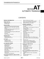
AT-1
AUTOMATIC TRANSMISSION
C TRANSMISSION/TRANSAXLE
CONTENTS
D
E
F
G
H
I
J
K
L
M
SECTION AT
A
B
AT
Revision; 2004 April 2003 FX
AUTOMATIC TRANSMISSION
INDEX FOR DTC 5
Alphabetical Index 5
DTC No. Index 6
PRECAUTIONS 7
Precautions for Supplemental Restraint System
(SRS) “AIR BAG” and “SEAT BELT PRE-TEN-
SIONER” 7
Precautions for On Board Diagnostic (OBD) System
of A/T and Engine 7
Precautions 7
Service Notice or Precautions 8
Wiring Diagrams and Trouble Diagnosis 9
PREPARATION 10
Special Service Tools 10
Commercial Service Tools 11
A/T FLUID 12
Changing A/T Fluid 12
Checking A/T Fluid 12
A/T CONTROL SYSTEM 14
Cross-Sectional View (2WD Models) 14
Cross-Sectional View (AWD Models) 15
Shift Mechanism 16
TCM Function 27
CAN Communication 28
Input/Output Signal of TCM 42
Line Pressure Control 43
Shift Control 44
Lock-Up Control 45
Engine Brake Control 46
Control Valve 47
ON BOARD DIAGNOSTIC (OBD) SYSTEM 49
Introduction 49
OBD-II Function for A/T System 49
One or Two Trip Detection Logic of OBD-II 49
OBD-II Diagnostic Trouble Code (DTC) 49
Malfunction Indicator Lamp (MIL) 52
TROUBLE DIAGNOSIS 53
DTC Inspection Priority Chart 53
Fail-Safe 53
How To Perform Trouble Diagnosis For Quick and
Accurate Repair 55
A/T Electrical Parts Location 60
Circuit Diagram 61
Wiring Diagram — AT — 62
Inspections Before Trouble Diagnosis 71
Check Before Engine is Started 75
Check at Idle 75
Cruise Test - Part 1 76
Cruise Test - Part 2 78
Cruise Test - Part 3 79
Vehicle Speed When Shifting Gears 80
Vehicle Speed When Performing and Releasing
Complete Lock-up 80
Vehicle Speed When Performing and Releasing
Slip Lock-up 81
Symptom Chart 82
TCM Input/Output Signal Reference Values 107
CONSULT-II 108
Diagnostic Procedure Without CONSULT-II 120
DTC U1000 CAN COMMUNICATION LINE 122
Description 122
On Board Diagnosis Logic 122
Possible Cause 122
DTC Confirmation Procedure 122
Diagnostic Procedure 123
DTC P0615 START SIGNAL CIRCUIT 124
Description 124
CONSULT-II Reference Value 124
On Board Diagnosis Logic 124
Possible Cause 124
DTC Confirmation Procedure 124
Diagnostic Procedure 125
DTC P0705 PARK/NEUTRAL POSITION SWITCH .127
Description 127
CONSULT-II Reference Value 127
On Board Diagnosis Logic 127
Possible Cause 127
DTC Confirmation Procedure 127
Diagnostic Procedure 128
DTC P0720 VEHICLE SPEED SENSOR A/T (REV-
AT-2
Revision; 2004 April 2003 FX
OLUTION SENSOR) 129
Description 129
CONSULT-II Reference Value 129
On Board Diagnosis Logic 129
Possible Cause 129
DTC Confirmation Procedure 129
Diagnostic Procedure 130
DTC P0725 ENGINE SPEED SIGNAL 131
Description 131
CONSULT-II Reference Value 131
On Board Diagnosis Logic 131
Possible Cause 131
DTC Confirmation Procedure 131
Diagnostic Procedure 131
DTC P0740 TORQUE CONVERTER CLUTCH
SOLENOID VALVE 133
Description 133
CONSULT-II Reference Value 133
On Board Diagnosis Logic 133
Possible Cause 133
DTC Confirmation Procedure 133
Diagnostic Procedure 134
DTC P0744 A/T TCC S/V FUNCTION (LOCK-UP) .135
Description 135
CONSULT-II Reference Value 135
On Board Diagnosis Logic 135
Possible Cause 135
DTC Confirmation Procedure 135
Diagnostic Procedure 136
DTC P0745 LINE PRESSURE SOLENOID VALVE .137
Description 137
CONSULT-II Reference Value 137
On Board Diagnosis Logic 137
Possible Cause 137
DTC Confirmation Procedure 137
Diagnostic Procedure 138
DTC P1701 TRANSMISSION CONTROL MODULE
(POWER SUPPLY) 139
Description 139
On Board Diagnosis Logic 139
Possible Cause 139
DTC Confirmation Procedure 139
Diagnostic Procedure 140
DTC P1702 TRANSMISSION CONTROL MODULE
(RAM) 142
Description 142
On Board Diagnosis Logic 142
Possible Cause 142
DTC Confirmation Procedure 142
Diagnostic Procedure 142
DTC P1703 TRANSMISSION CONTROL MODULE
(ROM) 143
Description 143
On Board Diagnosis Logic 143
Possible Cause 143
DTC Confirmation Procedure 143
Diagnostic Procedure 143
DTC P1704 TRANSMISSION CONTROL MODULE
(EEPROM) 144
Description 144
On Board Diagnosis Logic 144
Possible Cause 144
DTC Confirmation Procedure 144
Diagnostic Procedure 144
DTC P1705 THROTTLE POSITION SENSOR 145
Description 145
On Board Diagnosis Logic 145
Possible Cause 145
DTC Confirmation Procedure 145
Diagnostic Procedure 145
DTC P1710 A/T FLUID TEMPERATURE SENSOR
CIRCUIT 147
Description 147
CONSULT-II Reference Value 147
On Board Diagnosis Logic 147
Possible Cause 147
DTC Confirmation Procedure 147
Diagnostic Procedure 148
DTC P1716 TURBINE REVOLUTION SENSOR 149
Description 149
CONSULT-II Reference Value 149
On Board Diagnosis Logic 149
Possible Cause 149
DTC Confirmation Procedure 149
Diagnostic Procedure 150
DTC P1721 VEHICLE SPEED SENSOR MTR 151
Description 151
CONSULT-II Reference Value 151
On Board Diagnosis Logic 151
Possible Cause 151
DTC Confirmation Procedure 151
Diagnostic Procedure 151
DTC P1730 A/T INTERLOCK 153
Description 153
On Board Diagnosis Logic 153
Possible Cause 153
DTC Confirmation Procedure 153
Judgement of A/T Interlock 154
Diagnostic Procedure 154
DTC P1731 A/T 1ST ENGINE BRAKING 156
Description 156
CONSULT-II Reference Value 156
On Board Diagnosis Logic 156
Possible Cause 156
DTC Confirmation Procedure 156
Diagnostic Procedure 157
DTC P1752 INPUT CLUTCH SOLENOID VALVE 158
Description 158
CONSULT-II Reference Value 158
On Board Diagnosis Logic 158
Possible Cause 158
DTC Confirmation Procedure 158
Diagnostic Procedure 159
DTC P1754 INPUT CLUTCH SOLENOID VALVE
FUNCTION 160
Description 160
CONSULT-II Reference Value 160
On Board Diagnosis Logic 160
AT-3
D
E
F
G
H
I
J
K
L
M
A
B
AT
Revision; 2004 April 2003 FX
Possible Cause 160
DTC Confirmation Procedure 160
Diagnostic Procedure 161
DTC P1757 FRONT BRAKE SOLENOID VALVE 162
Description 162
CONSULT-II Reference Value 162
On Board Diagnosis Logic 162
Possible Cause 162
DTC Confirmation Procedure 162
Diagnostic Procedure 163
DTC P1759 FRONT BRAKE SOLENOID VALVE
FUNCTION 164
Description 164
CONSULT-II Reference Value 164
On Board Diagnosis Logic 164
Possible Cause 164
DTC Confirmation Procedure 164
Diagnostic Procedure 165
DTC P1762 DIRECT CLUTCH SOLENOID VALVE . 166
Description 166
CONSULT-II Reference Value 166
On Board Diagnosis Logic 166
Possible Cause 166
DTC Confirmation Procedure 166
Diagnostic Procedure 167
DTC P1764 DIRECT CLUTCH SOLENOID VALVE
FUNCTION 168
Description 168
CONSULT-II Reference Value 168
On Board Diagnosis Logic 168
Possible Cause 168
DTC Confirmation Procedure 168
Diagnostic Procedure 169
DTC P1767 HIGH AND LOW REVERSE CLUTCH
SOLENOID VALVE 170
Description 170
CONSULT-II Reference Value 170
On Board Diagnosis Logic 170
Possible Cause 170
DTC Confirmation Procedure 170
Diagnostic Procedure 171
DTC P1769 HIGH AND LOW REVERSE CLUTCH
SOLENOID VALVE FUNCTION 172
Description 172
CONSULT-II Reference Value 172
On Board Diagnosis Logic 172
Possible Cause 172
DTC Confirmation Procedure 172
Diagnostic Procedure 173
DTC P1772 LOW COAST BRAKE SOLENOID
VALVE 174
Description 174
CONSULT-II Reference Value 174
On Board Diagnosis Logic 174
Possible Cause 174
DTC Confirmation Procedure 174
Diagnostic Procedure 175
DTC P1774 LOW COAST BRAKE SOLENOID
VALVE FUNCTION 176
Description 176
CONSULT-II Reference Value 176
On Board Diagnosis Logic 176
Possible Cause 176
DTC Confirmation Procedure 176
Diagnostic Procedure 177
DTC P1815 MANUAL MODE SWITCH 178
Description 178
CONSULT-II Reference Value in Data Monitor Mode
.178
On Board Diagnosis Logic 178
Possible Cause 178
DTC Confirmation Procedure 178
Diagnostic Procedure 178
Component Inspection 180
Position Indicator Lamp 180
DTC P1841 ATF PRESSURE SWITCH 1 181
Description 181
CONSULT-II Reference Value 181
On Board Diagnosis Logic 181
Possible Cause 181
DTC Confirmation Procedure 181
Diagnostic Procedure 182
DTC P1843 ATF PRESSURE SWITCH 3 183
Description 183
CONSULT-II Reference Value 183
On Board Diagnosis Logic 183
Possible Cause 183
DTC Confirmation Procedure 183
Diagnostic Procedure 184
DTC P1845 ATF PRESSURE SWITCH 5 185
Description 185
CONSULT-II Reference Value 185
On Board Diagnosis Logic 185
Possible Cause 185
DTC Confirmation Procedure 185
Diagnostic Procedure 186
DTC P1846 ATF PRESSURE SWITCH 6 187
Description 187
CONSULT-II Reference Value 187
On Board Diagnosis Logic 187
Possible Cause 187
DTC Confirmation Procedure 187
Diagnostic Procedure 188
CLOSED THROTTLE POSITION AND WIDE OPEN
THROTTLE POSITION CIRCUIT 189
Diagnostic Procedure 189
BRAKE SIGNAL CIRCUIT 190
Diagnostic Procedure 190
TROUBLE DIAGNOSIS FOR SYMPTOMS 191
A/T CHECK Indicator Lamp Does Not Come On . 191
Engine Cannot Be Started In “P” or “N” Position 192
In “P” Position, Vehicle Moves When Pushed 193
In “N” Position, Vehicle Moves 194
Large Shock (“N” to “D” Position) 195
Vehicle Does Not Creep Backward In “R” Position .198
Vehicle Does Not Creep Forward In “D” Position . 201
Vehicle Cannot Be Started From D
1 204
A/T Does Not Shift: D
1 → D2 206
AT-4
Revision; 2004 April 2003 FX
A/T Does Not Shift: D
2 → D3 209
A/T Does Not Shift: D
3 → D4 211
A/T Does Not Shift: D
4 → D5 214
A/T Does Not Perform Lock-Up 216
A/T Does Not Hold Lock-Up Condition 219
Lock-Up Is Not Released 220
Engine Speed Does Not Return To Idle 221
Cannot Be Changed to Manual Mode 222
A/T Does Not Shift: 5th Gear → 4th Gear 223
A/T Does Not Shift: 4th Gear → 3rd Gear 225
A/T Does Not Shift: 3rd Gear → 2nd Gear 227
A/T Does Not Shift: 2nd Gear → 1st Gear 229
Vehicle Does Not Decelerate By Engine Brake 231
SHIFT CONTROL SYSTEM 233
Control Device Removal and Installation 233
Adjustment of A/T Position 234
Checking of A/T Position 234
A/T SHIFT LOCK SYSTEM 235
Description 235
Shift Lock System Electrical Parts Location 235
Wiring Diagram — AT — SHIFT 236
Diagnostic Procedure 237
KEY INTERLOCK CABLE 239
Components 239
Removal 240
Installation 241
ON-VEHICLE SERVICE 242
Control Valve with TCM and A/T Fluid Temperature
Sensor 2 242
Parking Components (2WD Models Only) 254
Rear Oil Seal 261
Revolution Sensor Components (2WD Models
Only) 262
AIR BREATHER HOSE 267
Removal and Installation 267
TRANSMISSION ASSEMBLY 269
Removal and Installation (2WD Models) 269
Removal and Installation (AWD Models) 272
OVERHAUL 277
Components 277
Oil Channel 287
Locations of Adjusting Shims, Needle Bearings,
Thrust Washers and Snap Rings 289
DISASSEMBLY 291
Disassembly 291
REPAIR FOR COMPONENT PARTS 308
Oil Pump 308
Front Sun Gear, 3rd One-Way Clutch 311
Front Carrier, Input Clutch, Rear Internal Gear 313
Mid Sun Gear, Rear Sun Gear, High and Low
Reverse Clutch Hub 319
High and Low Reverse Clutch 324
Direct Clutch 327
ASSEMBLY 329
Assembly (1) 329
Adjustment 341
Assembly (2) 343
SERVICE DATA AND SPECIFICATIONS (SDS) 351
General Specifications 351
Vehicle Speed When Shifting Gears 351
Vehicle Speed When Performing and Releasing
Complete Lock-up 352
Vehicle Speed When Performing and Releasing
Slip Lock-up 352
Stall Speed 353
Line Pressure 353
A/T Fluid Temperature Sensor 353
Turbine Revolution Sensor 353
Vehicle Speed Sensor A/T (Revolution Sensor) 353
Reverse Brake 353
Total End Play 353
INDEX FOR DTC
AT-5
D
E
F
G
H
I
J
K
L
M
A
B
AT
Revision; 2004 April 2003 FX
INDEX FOR DTC PFP:00024
Alphabetical Index ACS002L1
NOTE:
If DTC U1000 is displayed with other DTC, first perform the trouble diagnosis for DTC U1000. Refer to
AT-122
.
*1: These numbers are prescribed by SAE J2012.
*2: For VQ35DE engine.
*3: These malfunctions cannot be displayed MIL if another malfunction is assigned to MIL.
Items
(CONSULT-II screen terms)
DTC
Reference pageOBD-II Except OBD-II
CONSULT-II GST (*1) CONSULT-II only “A/T”
A/T 1ST E/BRAKING — P1731 AT-156
ATF PRES SW 1/CIRC — P1841 AT-181
ATF PRES SW 3/CIRC — P1843 AT-183
ATF PRES SW 5/CIRC — P1845 AT-185
ATF PRES SW 6/CIRC — P1846 AT-187
A/T INTERLOCK P1730 P1730 AT-153
A/T TCC S/V FNCTN P0744 P0744 AT-135
ATF TEMP SEN/CIRC P0710 P1710 AT-147
CAN COMM CIRCUIT U1000 U1000 AT-122
D/C SOLENOID/CIRC P1762 P1762 AT-166
D/C SOLENOID FNCTN P1764 (*3) P1764 AT-168
ENGINE SPEED SIG P0725 (*2) P0725 AT-131
FR/B SOLENOID/CIRC P1757 P1757 AT-162
FR/B SOLENOID FNCT P1759 P1759 AT-164
HLR/C SOL/CIRC P1767 P1767 AT-170
HLR/C SOL FNCTN P1769 (*3) P1769 AT-172
I/C SOLENOID/CIRC P1752 P1752 AT-158
I/C SOLENOID FNCTN P1754 (*3) P1754 AT-160
L/PRESS SOL/CIRC P0745 P0745 AT-137
LC/B SOLENOID/CIRC P1772 P1772 AT-174
LC/B SOLENOID FNCT P1774 P1774 AT-176
MANU MODE SW/CIR — P1815 AT-178
PNP SW/CIRC P0705 P0705 AT-127
STARTER RELAY/CIRC — P0615 AT-124
TCC SOLENOID/CIRC P0740 P0740 AT-133
TCM·EEPROM — P1704 AT-144
TCM-POWER SUPPLY — P1701 AT-139
TCM·RAM — P1702 AT-142
TCM·ROM — P1703 AT-143
TP SEN/CIRC A/T P1705 (*2) P1705 AT-145
TURBINE REV S/CIRC P1716 P1716 AT-149
VEH SPD SE/CIR·MTR — P1721 AT-151
VEH SPD SEN/CIR AT P0720 P0720 AT-129
AT-6
INDEX FOR DTC
Revision; 2004 April 2003 FX
DTC No. Index ACS002L2
NOTE:
If DTC U1000 is displayed with other DTC, first perform the trouble diagnosis for DTC U1000. Refer to
AT-122
.
*1: These numbers are prescribed by SAE J2012.
*2: For VQ35DE engine.
*3: These malfunctions cannot be displayed MIL if another malfunction is assigned to MIL.
DTC
Items
(CONSULT-II screen terms)
Reference pageOBD-II Except OBD-II
CONSULT-II GST (*1) CONSULT-I only “A/T”
— P0615 STARTER RELAY/CIRC AT-124
P0705 P0705 PNP SW/CIRC AT-127
P0710 P1710 ATF TEMP SEN/CIRC AT-147
P0720 P0720 VEH SPD SEN/CIR AT AT-129
P0725 (*2) P0725 ENGINE SPEED SIG AT-131
P0740 P0740 TCC SOLENOID/CIRC AT-133
P0744 P0744 A/T TCC S/V FNCTN AT-135
P0745 P0745 L/PRESS SOL/CIRC AT-137
— P1701 TCM-POWER SUPPLY AT-139
— P1702 TCM·RAM AT-142
— P1703 TCM·ROM AT-143
— P1704 TCM·EEPROM AT-144
P1705 (*2) P1705 TP SEN/CIRC A/T AT-145
P1716 P1716 TURBINE REV S/CIRC AT-149
— P1721 VEH SPD SE/CIR·MTR AT-151
P1730 P1730 A/T INTERLOCK AT-153
— P1731 A/T 1ST E/BRAKING AT-156
P1752 P1752 I/C SOLENOID/CIRC AT-158
P1754 (*3) P1754 I/C SOLENOID FNCTN AT-160
P1757 P1757 FR/B SOLENOID/CIRC AT-162
P1759 (*3) P1759 FR/B SOLENOID FNCT AT-164
P1762 P1762 D/C SOLENOID/CIRC AT-166
P1764 (*3) P1764 D/C SOLENOID FNCTN AT-168
P1767 P1767 HLR/C SOL/CIRC AT-170
P1769 P1769 HLR/C SOL FNCTN AT-172
P1772 P1772 LC/B SOLENOID/CIRC AT-174
P1774 P1774 LC/B SOLENOID FNCT AT-176
— P1815 MANU MODE SW/CIRC AT-178
— P1841 ATF PRES SW 1/CIRC AT-181
— P1843 ATF PRES SW 3/CIRC AT-183
— P1845 ATF PRES SW 5/CIRC AT-185
— P1846 ATF PRES SW 6/CIRC AT-187
U1000 U1000 CAN COMM CIRCUIT AT-122
PRECAUTIONS
AT-7
D
E
F
G
H
I
J
K
L
M
A
B
AT
Revision; 2004 April 2003 FX
PRECAUTIONS PFP:00001
Precautions for Supplemental Restraint System (SRS) “AIR BAG” and “SEAT
BELT PRE-TENSIONER”
ACS004LW
The Supplemental Restraint System such as “AIR BAG” and “SEAT BELT PRE-TENSIONER”, used along
with a front seat belt, helps to reduce the risk or severity of injury to the driver and front passenger for certain
types of collision. This system includes seat belt switch inputs and dual stage front air bag modules. The SRS
system uses the seat belt switches to determine the front air bag deployment, and may only deploy one front
air bag, depending on the severity of a collision and whether the front occupants are belted or unbelted.
Information necessary to service the system safely is included in the SRS and SB section of this Service Man-
ual.
WARNING:
● To avoid rendering the SRS inoperative, which could increase the risk of personal injury or death
in the event of a collision which would result in air bag inflation, all maintenance must be per-
formed by an authorized NISSAN/INFINITI dealer.
● Improper maintenance, including incorrect removal and installation of the SRS, can lead to per-
sonal injury caused by unintentional activation of the system. For removal of Spiral Cable and Air
Bag Module, see the SRS section.
● Do not use electrical test equipment on any circuit related to the SRS unless instructed to in this
Service Manual. SRS wiring harnesses can be identified by yellow and/or orange harnesses or
harness connectors.
Precautions for On Board Diagnostic (OBD) System of A/T and Engine ACS002L5
The ECM has an on board diagnostic system. It will light up the malfunction indicator lamp (MIL) to warn the
driver of a malfunction causing emission deterioration.
CAUTION:
● Be sure to turn the ignition switch “OFF” and disconnect the negative battery cable before any
repair or inspection work. The open/short circuit of related switches, sensors, solenoid valves,
etc. Will cause the MIL to light up.
● Be sure to connect and lock the connectors securely after work. A loose (unlocked) connector will
cause the MIL to light up due to an open circuit. (Be sure the connector is free from water, grease,
dirt, bent terminals, etc.)
● Be sure to route and secure the harnesses properly after work. Interference of the harness with a
bracket, etc. May cause the MIL to light up due to a short circuit.
● Be sure to connect rubber tubes properly after work. A misconnected or disconnected rubber tube
may cause the MIL to light up due to a malfunction of the EGR system or fuel injection system, etc.
● Be sure to erase the unnecessary malfunction information (repairs completed) from the TCM and
ECM before returning the vehicle to the customer.
Precautions ACS002L6
● Before connecting or disconnecting the A/T assembly har-
ness connector, turn ignition switch “OFF” and disconnect
negative battery cable. Because battery voltage is applied
to TCM even if ignition switch is turned “OFF”.
SEF289H
AT-8
PRECAUTIONS
Revision; 2004 April 2003 FX
● After performing each TROUBLE DIAGNOSIS, perform
“DTC (Diagnostic Trouble Code) CONFIRMATION PROCE-
DURE”.
If the repair is completed the DTC should not be displayed in
the “DTC CONFIRMATION PROCEDURE”.
● Always use the specified brand of ATF. Refer to MA-12, "Fluids and Lubricants" .
● Use paper rags not cloth rags during work.
● After replacing the ATF, dispose of the waste oil using the methods prescribed by law, ordinance, etc.
● Before proceeding with disassembly, thoroughly clean the outside of the transmission. It is important to
prevent the internal parts from becoming contaminated by dirt or other foreign matter.
● Disassembly should be done in a clean work area.
● Use lint-free cloth or towels for wiping parts clean. Common shop rags can leave fibers that could interfere
with the operation of the transmission.
● Place disassembled parts in order for easier and proper assembly.
● All parts should be carefully cleaned with a general purpose, non-flammable solvent before inspection or
reassembly.
● Gaskets, seals and O-rings should be replaced any time the transmission is disassembled.
● It is very important to perform functional tests whenever they are indicated.
● The valve body contains precision parts and requires extreme care when parts are removed and serviced.
Place disassembled valve body parts in order for easier and proper assembly. Care will also prevent
springs and small parts from becoming scattered or lost.
● Properly installed valves, sleeves, plugs, etc. will slide along bores in valve body under their own weight.
● Before assembly, apply a coat of recommended ATF to all parts. Apply petroleum jelly to protect O-rings
and seals, or hold bearings and washers in place during assembly. Do not use grease.
● Extreme care should be taken to avoid damage to O-rings, seals and gaskets when assembling.
● After overhaul, refill the transmission with new ATF.
● When the A/T drain plug is removed, only some of the fluid is drained. Old A/T fluid will remain in torque
converter and ATF cooling system.
Always follow the procedures under “Changing A/T Fluid” in the AT section when changing A/T fluid. Refer
to AT-12, "
Changing A/T Fluid" , AT-12, "Checking A/T Fluid" .
Service Notice or Precautions ACS002L7
OBD-II SELF-DIAGNOSIS
● A/T self-diagnosis is performed by the TCM in combination with the ECM. The results can be read through
the blinking pattern of the A/T CHECK indicator or the malfunction indicator lamp (MIL). Refer to the table
on AT-110, "
Self-diagnostic Result Test Mode" for the indicator used to display each self-diagnostic result.
● The self-diagnostic results indicated by the MIL are automatically stored in both the ECM and TCM mem-
ories.
Always perform the procedure on AT-50, "
HOW TO ERASE DTC" to complete the repair and avoid
unnecessary blinking of the MIL.
For details of OBD-II, refer to EC-67, "
ON BOARD DIAGNOSTIC (OBD) SYSTEM" (for VQ35DE) or EC-708,
"ON BOARD DIAGNOSTIC (OBD) SYSTEM" (for VK45DE).
● Certain systems and components, especially those related to OBD, may use the new style slide-
locking type harness connector. For description and how to disconnect, refer to PG-89, "
HAR-
NESS CONNECTOR" .
SEF217U
PRECAUTIONS
AT-9
D
E
F
G
H
I
J
K
L
M
A
B
AT
Revision; 2004 April 2003 FX
Wiring Diagrams and Trouble Diagnosis ACS002L8
When you read wiring diagrams, refer to the following:
● GI-15, "How to Read Wiring Diagrams".
● PG-3, "POWER SUPPLY ROUTING CIRCUIT" for power distribution circuit.
When you perform trouble diagnosis, refer to the following:
● GI-11, "How to Follow Trouble Diagnoses".
● GI-27, "How to Perform Efficient Diagnosis for an Electrical Incident".
AT-10
PREPARATION
Revision; 2004 April 2003 FX
PREPARATION PFP:00002
Special Service Tools ACS002L9
The actual shapes of Kent-Moore tools may differ from those of special service tools illustrated here.
Tool number
(Kent-Moore No.)
Tool name
Description
ST2505S001
(J-34301-C)
Oil pressure gauge set
1 ST25051001
(—)
Oil pressure gauge
2 ST25052000
(—)
Hose
3 ST25053000
(—)
Joint pipe
4 ST25054000
(—)
Adapter
5 ST25055000
(—)
Adapter
Measuring line pressure
KV31103600
(J-45674)
Joint pipe adapter
(With ST25054000)
Measuring line pressure
ST33400001
(J-26082)
Drift
a: 60 mm (2.36 in) dia.
b: 47 mm (1.85 in) dia.
● Installing rear oil seal (2WD models)
● Installing oil pump housing oil seal
KV31102400
(J-34285 and J-34285-87)
Clutch spring compressor
a: 320 mm (12.60 in)
b: 174 mm (6.85 in)
Installing reverse brake return spring retainer
ST25850000
(J-25721-A)
Sliding hammer
a: 179 mm (7.05 in)
b: 70 mm (2.76 in)
c: 40 mm (1.57 in)
d: M12X1.75P
Remove oil pump assembly
ZZA0600D
ZZA1227D
NT086
NT423
NT422
PREPARATION
AT-11
D
E
F
G
H
I
J
K
L
M
A
B
AT
Revision; 2004 April 2003 FX
Commercial Service Tools ACS002LA
Tool name Description
Power tool Loosening bolts and nuts
Drift
a: 22mm (0.87 in) dia.
Installing manual shaft oil seals
Drift
a: 64 mm (2.52 in) dia.
Installing rear oil seal (AWD models)
PBIC0190E
NT083
SCIA5338E
AT-12
A/T FLUID
Revision; 2004 April 2003 FX
A/T FLUID PFP:KLE40
Changing A/T Fluid ACS002LB
1. Warm up ATF.
2. Stop engine.
3. Remove the tightening bolt for ATF level gauge.
4. Drain ATF from drain plug and refill with new ATF. Always refill same volume with drained fluid.
● To replace the ATF, pour in new fluid at the charging pipe with the engine idling and at the same time
drain the old fluid from the radiator cooler hose return side.
● When the color of the fluid coming out is about the same as the color of the new fluid, the replacement
is complete. The amount of new transmission fluid to use should be 30 to 50% increase of the stipu-
lated amount.
CAUTION:
● Use only Genuine NISSAN ATF Matic Fluid J. Do not mix with other fluid.
● Using automatic transmission fluid other than Genuine NISSAN ATF Matic Fluid J will cause
deterioration in driveability and automatic transmission durability, and may damage the auto-
matic transmission, which is not covered by the warranty.
● When filling ATF, take care not to splash heat generating parts such as exhaust with ATF.
● Do not reuse drain plug gasket.
5. Run engine at idle speed for 5 minutes.
6. Check fluid level and condition. Refer to AT-12, "
Checking A/T Fluid" . If fluid is still dirty, repeat step 2.
through 5.
7. Install the removed ATF level gauge in the fluid charging pipe.
Checking A/T Fluid ACS002LC
1. Warm up engine.
2. Check for fluid leakage.
3. Remove the tightening bolt for ATF level gauge.
4. Before driving, fluid level can be checked at fluid temperatures of 30 to 50°C (86 to 122°F) using “COLD”
range on ATF level gauge as follows.
a. Park vehicle on level surface and set parking brake.
b. Start engine and move selector lever through each gear position. Leave selector lever in “P” position.
c. Check fluid level with engine idling.
d. Remove ATF level gauge and wipe clean with lint-free paper.
CAUTION:
When wiping away the fluid level gauge, always use lint-free paper, not a cloth one.
e. Re-insert ATF level gauge into charging pipe as far as it will go.
CAUTION:
To check fluid level, insert the ATF level gauge until the cap contacts the end of the charging pipe,
with the gauge reversed from the normal attachment conditions.
f. Remove ATF level gauge and note reading. If reading is at low side of range, add fluid to the charging
pipe.
CAUTION:
Do not overfill.
ATF: NISSAN Matic Fluid J
Fluid capacity: 10.3 (10-7/8 US qt, 9-1/8 lmp qt)
Drain plug:
: 34 N·m (3.5 kg-m, 25 ft-lb)
Level gauge bolt:
: 5.1 N·m (0.52 kg-m, 45 in-lb)
A/T FLUID
AT-13
D
E
F
G
H
I
J
K
L
M
A
B
AT
Revision; 2004 April 2003 FX
5. Drive vehicle for approximately 5 minutes in urban areas.
6. Make the fluid temperature approximately 65°C (149°F).
NOTE:
Fluid level will be greatly affected by temperature as shown in figure. Therefore, be certain to per-
form operation while checking data with CONSULT-II.
a. Connect CONSULT-II to data link connector.
b. Select “MAIN SIGNALS” in “DATA MONITOR” mode for “A/T” with CONSULT-II.
c. Read out the value of “ATF TEMP 1”.
7. Re-check fluid level at fluid temperatures of approximately 65°C (149°F) using “HOT” range on A/T fluid
level gauge.
CAUTION:
● When wiping away the fluid level gauge, always use lint-free paper, not a cloth one.
● To check fluid level, insert the ATF level gauge until the
cap contacts the end of the charging pipe, with the gauge
reversed from the normal attachment conditions as
shown.
8. Check fluid condition.
● If fluid is very dark or smells burned, refer to check operation
of A/T. Flush cooling system after repair of A/T.
● If ATF contains frictional material (clutches, bands, etc.),
replace radiator and flush cooler line using cleaning solvent
and compressed air after repair of A/T. Refer to CO-14,
"RADIATOR" (for VQ35DE) or CO-38, "RADIATOR" (for
VK45DE).
9. Install the removed ATF level gauge in the fluid charging pipe.
Level gauge bolt:
: 5.1 N·m (0.52 kg-m, 45 in-lb)
SLIA0016E
SCIA1684E
AT-14
A/T CONTROL SYSTEM
Revision; 2004 April 2003 FX
A/T CONTROL SYSTEM PFP:31036
Cross-Sectional View (2WD Models) ACS008RW
1. Front planetary gear 2. Mid planetary gear 3. Rear planetary gear
4. Direct clutch 5. High and low reverse clutch 6. Reverse brake
7. Drum support 8. Forward brake 9. Low coast brake
10. Input shaft 11. Torque converter 12. Oil pump
13. Front brake 14. 3rd one-way clutch 15. Input clutch
16. 1st one-way clutch 17. Control valve with TCM 18. Forward one-way clutch
19. Rear extension 20. Output shaft
SCIA5262E
A/T CONTROL SYSTEM
AT-15
D
E
F
G
H
I
J
K
L
M
A
B
AT
Revision; 2004 April 2003 FX
Cross-Sectional View (AWD Models) ACS008RX
1. Front planetary gear 2. Mid planetary gear 3. Rear planetary gear
4. Direct clutch 5. High and low reverse clutch 6. Reverse brake
7. Drum support 8. Forward brake 9. Low coast brake
10. Input shaft 11. Torque converter 12. Oil pump
13. Front brake 14. 3rd one-way clutch 15. Input clutch
16. 1st one-way clutch 17. Control valve with TCM 18. Forward one-way clutch
19. Adapter case 20. Output shaft
SCIA5263E
AT-16
A/T CONTROL SYSTEM
Revision; 2004 April 2003 FX
Shift Mechanism ACS002LE
The automatic transmission uses compact dual planetary gear systems to improve power-transmission effi-
ciency, simplify construction and reduce weight.
It also employs an optimum shift control and super wide gear ratios. They improve starting performance and
acceleration during medium and high-speed operation.
CONSTRUCTION
FUNCTION OF CLUTCH AND BRAKE
1. Front brake 2. Input clutch 3. Direct clutch
4. High and low reverse clutch 5. Reverse brake 6. Forward brake
7. Low coast brake 8. 1st one-way clutch 9. Forward one-way clutch
10. 3rd one-way clutch 11. Front sun gear 12. Input shaft
13. Mid internal gear 14. Front internal gear 15. Rear carrier
16. Rear sun gear 17. Mid sun gear 18. Front carrier
19. Mid carrier 20. Rear internal gear 21. Output shaft
22. Parking gear 23. Parking pawl
PCIA0002J
Name of the Part Abbreviation Function
Front brake (1) FR/B Fastens the front sun gear (11).
Input clutch (2) I/C
Connects the input shaft (12), the front internal gear (14) and the mid internal
gear (13).
Direct clutch (3) D/C Connects the rear carrier (15) and the rear sun gear (16).
High and low reverse clutch (4) HLR/C Connects the mid sun gear (17) and the rear sun gear (16).
Reverse brake (5) R/B Fastens the rear carrier (15).
Forward brake (6) F/B Fastens the mid sun gear (17).
Low coast brake (7) LC/B Fastens the mid sun gear (17).
1st one-way clutch (8) 1st/O.C
Allows the rear sun gear (16) to turn freely forward relative to the mid sun gear
(17) but fastens it for reverse rotation.
Forward one-way clutch (9) F/O.C
Allows the mid sun gear (17) to turn freely in the forward direction but fastens it
for reverse rotation.
3rd one-way clutch (10) 3rd/O.C
Allows the front sun gear (11) to turn freely in the forward direction but fastens
it for reverse rotation.
A/T CONTROL SYSTEM
AT-17
D
E
F
G
H
I
J
K
L
M
A
B
AT
Revision; 2004 April 2003 FX
CLUTCH AND BAND CHART
SCIA4755E
AT-18
A/T CONTROL SYSTEM
Revision; 2004 April 2003 FX
POWER TRANSMISSION
“N” Position
Since both the forward brake and the reverse brake are released, torque from the input shaft drive is not trans-
mitted to the output shaft.
“P” Position
● The same as for the “N” position, both the forward brake and the reverse brake are released, so torque
from the input shaft drive is not transmitted to the output shaft.
● The parking pawl linked with the select lever meshes with the parking gear and fastens the output shaft
mechanically.
1. Front brake 2. Input clutch 3. Direct clutch
4. High and low reverse clutch 5. Reverse brake 6. Forward brake
7. Low coast brake 8. 1st one-way clutch 9. Forward one-way clutch
10. 3rd one-way clutch 11. Front sun gear 12. Input shaft
13. Mid internal gear 14. Front internal gear 15. Rear carrier
16. Rear sun gear 17. Mid sun gear 18. Front carrier
19. Mid carrier 20. Rear internal gear 21. Output shaft
22. Parking gear 23. Parking pawl
PCIA0003J
A/T CONTROL SYSTEM
AT-19
D
E
F
G
H
I
J
K
L
M
A
B
AT
Revision; 2004 April 2003 FX
“D1 ” Position
● The forward brake and the forward one-way clutch regulate reverse rotation of the mid sun gear.
● The 1st one-way clutch regulates reverse rotation of the rear sun gear.
● The 3rd one-way clutch regulates reverse rotation of the front sun gear.
● During deceleration, the mid sun gear turns forward, so the forward one-way clutch idles and the engine
brake is not activated.
1. Front brake 2. Input clutch 3. Direct clutch
4. High and low reverse clutch 5. Reverse brake 6. Forward brake
7. Low coast brake 8. 1st one-way clutch 9. Forward one-way clutch
10. 3rd one-way clutch 11. Front sun gear 12. Input shaft
13. Mid internal gear 14. Front internal gear 15. Rear carrier
16. Rear sun gear 17. Mid sun gear 18. Front carrier
19. Mid carrier 20. Rear internal gear 21. Output shaft
22. Parking gear 23. Parking pawl
SCIA1512E
AT-20
A/T CONTROL SYSTEM
Revision; 2004 April 2003 FX
“M1” Position
● The front brake fastens the front sun gear.
● The forward brake and the forward one-way clutch regulate reverse rotation of the mid sun gear.
● High and low reverse clutch connects the rear sun gear and the mid sun gear.
● The low coast brake fastens the mid sun gear.
● During deceleration, the low coast brake regulates forward rotation of the mid sun gear and the engine
brake functions.
1. Front brake 2. Input clutch 3. Direct clutch
4. High and low reverse clutch 5. Reverse brake 6. Forward brake
7. Low coast brake 8. 1st one-way clutch 9. Forward one-way clutch
10. 3rd one-way clutch 11. Front sun gear 12. Input shaft
13. Mid internal gear 14. Front internal gear 15. Rear carrier
16. Rear sun gear 17. Mid sun gear 18. Front carrier
19. Mid carrier 20. Rear internal gear 21. Output shaft
22. Parking gear 23. Parking pawl
SCIA1513E
A/T CONTROL SYSTEM
AT-21
D
E
F
G
H
I
J
K
L
M
A
B
AT
Revision; 2004 April 2003 FX
“D2 ” Position
● The forward brake and the forward one-way clutch regulate reverse rotation of the mid sun gear.
● The 3rd one-way clutch regulates reverse rotation of the front sun gear.
● The direct clutch is coupled, and the rear carrier and rear sun gear are connected.
● During deceleration, the mid sun gear turns forward, so the forward one-way clutch idles and engine
brake is not activated.
1. Front brake 2. Input clutch 3. Direct clutch
4. High and low reverse clutch 5. Reverse brake 6. Forward brake
7. Low coast brake 8. 1st one-way clutch 9. Forward one-way clutch
10. 3rd one-way clutch 11. Front sun gear 12. Input shaft
13. Mid internal gear 14. Front internal gear 15. Rear carrier
16. Rear sun gear 17. Mid sun gear 18. Front carrier
19. Mid carrier 20. Rear internal gear 21. Output shaft
22. Parking gear 23. Parking pawl
SCIA1514E
AT-22
A/T CONTROL SYSTEM
Revision; 2004 April 2003 FX
“M2” Position
● The front brake fastens the front sun gear.
● The forward brake and the forward one-way clutch regulate reverse rotation of the mid sun gear.
● The direct clutch is coupled, and the rear carrier and rear sun gear are connected.
● The low coast brake fastens the mid sun gear.
● During deceleration, the low coast brake regulates forward rotation of the mid sun gear and the engine
brake functions.
1. Front brake 2. Input clutch 3. Direct clutch
4. High and low reverse clutch 5. Reverse brake 6. Forward brake
7. Low coast brake 8. 1st one-way clutch 9. Forward one-way clutch
10. 3rd one-way clutch 11. Front sun gear 12. Input shaft
13. Mid internal gear 14. Front internal gear 15. Rear carrier
16. Rear sun gear 17. Mid sun gear 18. Front carrier
19. Mid carrier 20. Rear internal gear 21. Output shaft
22. Parking gear 23. Parking pawl
SCIA1515E
A/T CONTROL SYSTEM
AT-23
D
E
F
G
H
I
J
K
L
M
A
B
AT
Revision; 2004 April 2003 FX
“D3 ” and “M3” Position
● The front brake fastens the front sun gear.
● The direct clutch is coupled, and the rear carrier and rear sun gear are connected.
● The high and low reverse clutch is coupled, and the mid sun gear and rear sun gear are connected.
1. Front brake 2. Input clutch 3. Direct clutch
4. High and low reverse clutch 5. Reverse brake 6. Forward brake
7. Low coast brake 8. 1st one-way clutch 9. Forward one-way clutch
10. 3rd one-way clutch 11. Front sun gear 12. Input shaft
13. Mid internal gear 14. Front internal gear 15. Rear carrier
16. Rear sun gear 17. Mid sun gear 18. Front carrier
19. Mid carrier 20. Rear internal gear 21. Output shaft
22. Parking gear 23. Parking pawl
SCIA1516E
AT-24
A/T CONTROL SYSTEM
Revision; 2004 April 2003 FX
“D4 ” and “M4” Position
● The direct clutch is coupled, and the rear carrier and rear sun gear are connected.
● The high and low reverse clutch is coupled, and the mid sun gear and rear sun gear are connected.
● The input clutch is coupled, and the front internal gear and mid internal gear are connected.
● The drive power is conveyed to the front internal gear, mid internal gear, and rear carrier and the three
planetary gears rotate forward as one unit.
1. Front brake 2. Input clutch 3. Direct clutch
4. High and low reverse clutch 5. Reverse brake 6. Forward brake
7. Low coast brake 8. 1st one-way clutch 9. Forward one-way clutch
10. 3rd one-way clutch 11. Front sun gear 12. Input shaft
13. Mid internal gear 14. Front internal gear 15. Rear carrier
16. Rear sun gear 17. Mid sun gear 18. Front carrier
19. Mid carrier 20. Rear internal gear 21. Output shaft
22. Parking gear 23. Parking pawl
SCIA1517E
A/T CONTROL SYSTEM
AT-25
D
E
F
G
H
I
J
K
L
M
A
B
AT
Revision; 2004 April 2003 FX
“D5 ” and “M5” Position
● The front brake fastens the front sun gear.
● The input clutch is coupled, and the front internal gear and mid internal gear are connected.
● The high and low reverse clutch is coupled, and the mid sun gear and rear sun gear are connected.
1. Front brake 2. Input clutch 3. Direct clutch
4. High and low reverse clutch 5. Reverse brake 6. Forward brake
7. Low coast brake 8. 1st one-way clutch 9. Forward one-way clutch
10. 3rd one-way clutch 11. Front sun gear 12. Input shaft
13. Mid internal gear 14. Front internal gear 15. Rear carrier
16. Rear sun gear 17. Mid sun gear 18. Front carrier
19. Mid carrier 20. Rear internal gear 21. Output shaft
22. Parking gear 23. Parking pawl
SCIA4984E