FFD hệ THỐNG TRUYỀN LỰC TRƯỚC TRÊN INFINITI FX35, FX45 2003
Bạn đang xem bản rút gọn của tài liệu. Xem và tải ngay bản đầy đủ của tài liệu tại đây (1.58 MB, 40 trang )
FFD-1
FRONT FINAL DRIVE
D DRIVELINE/AXLE
CONTENTS
C
E
F
G
H
I
J
K
L
M
SECTION FFD
A
B
FFD
Revision; 2004 April 2003 FX
FRONT FINAL DRIVE
PRECAUTIONS 2
Precautions 2
PREPARATION 3
Special Service Tools 3
Commercial Service Tools 5
NOISE, VIBRATION AND HARSHNESS (NVH)
TROUBLESHOOTING 6
NVH Troubleshooting Chart 6
FRONT OIL SEAL 7
Removal and Installation 7
REMOVAL 7
INSTALLATION 8
SIDE OIL SEAL 9
Removal and Installation 9
REMOVAL 9
INSTALLATION 9
FRONT FINAL DRIVE ASSEMBLY 10
Removal and Installation (VQ35DE) 10
REMOVAL 10
INSTALLATION 10
Removal and Installation (VK45DE) 11
REMOVAL 11
INSTALLATION 11
Front Final Drive Breather Hose 12
REMOVAL AND INSTALLATION (VQ35DE) 12
REMOVAL AND INSTALLATION (VK45DE) 13
Components 14
COMPONENTS (VQ35DE) 14
COMPONENTS (VK45DE) 16
Side Shaft 18
BEARING AND OIL SEAL REPLACEMENT 18
EXTENSION TUBE REPLACEMENT 19
PRE-DISASSEMBLY INSPECTION 19
DISASSEMBLY AND ASSEMBLY 21
Differential Case Assembly 24
Installation Drive Pinion Assembly 27
DIFFERENTIAL CASE INSTALLATION 28
TOOTH CONTACT INSPECTION 30
TOOTH CONTACT ADJUSTMENT 31
TOTAL PRELOAD INSPECTION 33
DRIVE PINION PRELOAD ADJUSTMENT 33
After Inspection 35
Carrier Cover Installation 37
SERVICE DATA AND SPECIFICATIONS (SDS) 38
General Specifications 38
Drive Gear Runout 38
Side Gear Adjustment 38
AVAILABLE SIDE GEAR THRUST WASHERS 38
SIDE BEARING PRELOAD ADJUSTING SHIMS 38
Drive Pinion Height Adjustment 39
AVAILABLE PINION HEIGHT ADJUSTING
WASHERS 39
Drive Pinion Preload Adjustment 39
AVAILABLE PINION HEIGHT ADJUSTING
WASHERS 39
Total Preload Adjustment 39
FFD-2
PRECAUTIONS
Revision; 2004 April 2003 FX
PRECAUTIONS PFP:00001
Precautions ADS000N3
CAUTION:
● Before starting diagnosis of the vehicle, understand symptoms well. Perform correct and system-
atic operations.
● Check for the correct installation status prior removal or disassembly. When mating marks are
required, be sure they do not interfere with the function of the parts they are applied to.
● Carry out an overhaul in a clean work place, Using a dust proof room is recommended.
● Before disassembly, using steam or white gasoline, completely remove sand and mud from the
exterior the unit, preventing them from entering into the unit during disassembly or assembly.
● Check appearance of the disassembled parts for damage, deformation, and abnormal wear. If a
malfunction is detected, replace it with a new one.
● Normally replace lock pins, oil seals, and bearings with new ones every times they are removed.
● In principle, tighten bolts or nuts gradually in several steps working diagonally from inside to out-
side. If tightening sequence is specified, observe it.
● Clean and flush the parts sufficiently and blow them dry.
● Be careful not to damage the sliding surfaces and mating surface.
● When applying sealant, remove the old sealant from the mounting surface; then remove any mois-
ture, oil, and foreign materials from the application and mounting surfaces.
● Always use shop paper for cleaning the inside of components.
● Avoid using cotton gloves or a shop cloth to prevent entering of lint.
● During assembly, observe the specified tightening torque, and new differential oil, Vaseline, or
multi-purpose grease, as specified for each vehicle, when necessary.
PREPARATION
FFD-3
C
E
F
G
H
I
J
K
L
M
A
B
FFD
Revision; 2004 April 2003 FX
PREPARATION PFP:00002
Special Service Tools ADS000N4
The actual shapes of Kent-Moore tools may differ from those of special service tools illustrated here.
Tool number (Kent-Moore No.)
Tool name
Description
ST33400001 (J26082)
a: 60 mm (2.36 in) dia.
b: 47 mm (1.85 in) dia.
Drift
● Installing front oil seal
● Installing right side oil sea
ST33290001 (J34286)
Outer race puller
● Removing side bearing outer race
● Removing side oil seal
● Removing front oil seal
ST3306S001 ( – )
ST33051001 (J22888-20) body
ST33061000 (J8107-2) adapter.
a: 28.5 mm (1.122 in) dia.
b: 38 mm (1.50 in) dia.
Puller set
Removing side bearing
ST30031000 (J22912-01)
Puller
Removing drive pinion bearing
ST33230000 ( – )
a: 51 mm (2.01 in) dia.
b: 41 mm (1.61 in) dia.
c: 28mm (1.10 in) dia.
Drift
Installing side bearing
ST33220000 ( – )
a: 32 mm (1.26 in) dia.
b: 31.5 mm (1.24 in) dia.
c: 21 mm (0.83 in) dia.
Drift
Installing side shaft bearing
KV31100300 ( – )
Pin punch
Removing and installing pinion mate shaft
lock pin
ZZA0702D
ZZA0601D
NT072
ZZA0700D
ZZA1046D
ZZA1046D
ZZA0515D
FFD-4
PREPARATION
Revision; 2004 April 2003 FX
ST30032000 ( – )
A: 80mm (3.15 in) dia.
B: 38 mm (1.50 in) dia.
C: 31 mm (1.22 in) dia.
Inner race adaptor
Installing drive pinion bearing
Installing side shaft and retainer
KV38102510 ( – )
a: 71 mm (2.80 in) dia.
b: 65 mm (2.56 in) dia.
Drift
Installing front oil seal
ST33210000 ( – )
a: 44 mm (1.73 in) dia.
b: 34.5 mm (1.36 in) dia.
c: 22 mm (0.87 in) dia.
Drift
● Removing side shaft bearing
● Installing left side oil seal
KV31103000 ( – )
a: 49 mm (1.93 in) dia.
b: 70 mm (2.76 in) dia.
Drift
● Installing drive pinion bearing outer race
● Installing side bearing outer race
ST1982000 ( – )
a: 70 mm (2.76 in) dia.
b: 50 mm (1.97 in) dia.
Drift
Installing side shaft oil seal
ST35321000 ( – )
a: 49 mm (1.93 in) dia.
b: 41 mm (1.61 in) dia.
Drift
Installing side bearing
Tool number (Kent-Moore No.)
Tool name
Description
SDIA0217J
ZZA0838D
ZZA1046D
ZZA1113D
ZZA0838D
ZZA1000D
PREPARATION
FFD-5
C
E
F
G
H
I
J
K
L
M
A
B
FFD
Revision; 2004 April 2003 FX
Commercial Service Tools ADS000N5
KV40104000 ( – )
a: 85 mm (3.35 in) dia.
b: 65 mm (2.56 in) dia.
Drive pinion flange wrench
Removing and installing drive pinion lock
nut
ST3127S000 (see J25765-A)
1. GG91030000
Torque wrench (J25765)
2. HT62940000 ( – )
Socket adapter (1/2″)
3. HT62900000 ( – )
Socket adapter (3/8″)
Preload gauge
Inspecting pinion bearing preload and total
preload
Tool number (Kent-Moore No.)
Tool name
Description
NT659
NT124
Tool name Description
Power tool Loosening bolts and nuts
PBIC0190E
FFD-6
NOISE, VIBRATION AND HARSHNESS (NVH) TROUBLESHOOTING
Revision; 2004 April 2003 FX
NOISE, VIBRATION AND HARSHNESS (NVH) TROUBLESHOOTING PFP:00003
NVH Troubleshooting Chart ADS000N6
Use the chart below to help you find the cause of the symptom. If necessary, repair or replace these parts.
×: Applicable
Reference page
Refer to FFD-35, "After Inspection" .
Refer to FFD-30, "TOOTH CONTACT INSPECTION" .
Refer to FFD-35, "After Inspection" .
Refer to RFD-13, "Pre-Inspection"
—
Refer to MA-32, "Checking Differential Gear Oil" .
NVH in PR section.
NVH in FAX, RAX, FSU and RSU sections.
NVH in WT section.
NVH in WT section.
NVH in FAX section.
NVH in BR section.
NVH in PS section.
Possible cause and suspected parts
Rough gear tooth
Improper gear contact
Tooth surfaces worn
Incorrect backlash
Companion flange excessive runout
Improper gear oil
Propeller shaft
Axle and suspension
Tires
Road wheel
Drive shaft
Brakes
Steering
Symptom Differential Noise ×××××××××××××
FRONT OIL SEAL
FFD-7
C
E
F
G
H
I
J
K
L
M
A
B
FFD
Revision; 2004 April 2003 FX
FRONT OIL SEAL PFP:38189
Removal and Installation ADS000N7
REMOVAL
1. Remove the front propeller shaft. Refer to PR-4, "Removal and Installation" .
2. Put a matching mark on the end of the drive pinion correspond-
ing to the B position matching mark on the final drive companion
flange.
CAUTION:
● For matching mark, use paint. Never damage drive pin-
ion.
● The matching mark B on the final drive companion flange
indicates the maximum vertical runout position.
3. Using the drive pinion flange wrench. Remove drive pinion lock
nut with tool.
4. Remove the companion flange using puller. (commercial service
tool)
5. Remove the front oil seal using outer race puller.
SDIA1609E
Tool number : KV40104000 ( – )
SDIA2055E
SDIA1642E
Tool number : ST33290001 (J34286)
SDIA1643E
FFD-8
FRONT OIL SEAL
Revision; 2004 April 2003 FX
INSTALLATION
1. Apply multi-purpose grease to sealing lips of the oil seal. Drive
the oil seal into the differential case using special service tool so
that the oil seal flush with the gear carrier end.
NOTE:
● When installing the front oil seal, be careful not to get it
inclined.
● Discard the old front oil seal. Always replace it with a new
one.
2. Install the companion flange while align the matching mark of
the drive pinion with the matching mark B of the companion
flange.
3. Apply oil to the drive pinion threads and the seating surface of
drive pinion lock nut.
4. Using the drive pinion flange wrench. Install drive pinion lock nut
with tool.
CAUTION:
Do not reuse the drive pinion lock nut. Always replace it
with a new one.
5. Install the front propeller shaft. Refer to PR-4, "
Removal and
Installation" .
Tool number A : ST33400001 (J26082)
B : KV38102510 ( – )
SDIA1645E
SDIA1609E
Tool number : KV40104000 ( – )
SDIA2055E
SIDE OIL SEAL
FFD-9
C
E
F
G
H
I
J
K
L
M
A
B
FFD
Revision; 2004 April 2003 FX
SIDE OIL SEAL PFP:33142
Removal and Installation ADS000N8
REMOVAL
Right Side:
1. Remove the front ABS wheel sensor.
2. Remove the front drive shaft. Refer to FAX-13, "
Removal and installation (Right Side)" .
3. Remove the side oil seal using puller.
Left Side:
1. Remove the front drive shaft. Refer to FAX-12, "FRONT DRIVE SHAFT"
2. Remove the side shaft assembly.
3. Remove the front final drive assembly from vehicle. Refer to FFD-10, "
Removal and Installation
(VQ35DE)" , FFD-11, "Removal and Installation (VK45DE)" .
4. Remove the side oil seal using puller.
INSTALLATION
Right Side:
1. Apply multi-purpose grease to sealing lips of side oil seal.
2. Using the drift, press-fit side oil seal so that its surface comes
face to face with the end surface of the case.
CAUTION:
● When installing the side oil seal, be careful not to get it
inclined.
● Do not reuse the side oil seal. Always replace the oil seal
with a new ones.
3. Install the front drive shaft. Refer to FAX-13, "
Removal and
installation (Right Side)" .
Left Side:
1. Apply multi-purpose grease to sealing lips of side oil seal.
2. Using the drift, press-fit side oil seal so that its surface comes
face to face with the end surface of the case.
CAUTION:
● When installing the side oil seal, be careful not to get it
inclined.
● Do not reuse the side oil seal. Always replace the oil seal
with a new ones.
3. Install the front drive shaft. Refer to FAX-12, "
Removal and
Installation (Left Side)" .
Tool number : ST33290001 (J34286)
SDIA1787E
Tool number : ST33290001 (J34286)
Tool number : ST33400001 (J26082)
SDIA1646E
Tool number : ST33210000 ( – )
SDIA1662E
FFD-10
FRONT FINAL DRIVE ASSEMBLY
Revision; 2004 April 2003 FX
FRONT FINAL DRIVE ASSEMBLY PFP:38500
Removal and Installation (VQ35DE) ADS000N9
REMOVAL
1. Remove the three engine mounting bracket upper bolts.
2. Remove the right bank catalytic converter. Refer to EX-3, "
EXHAUST SYSTEM" .
3. Remove the stabilizer assembly. Refer to FSU-16, "
STABILIZER BAR" .
4. Remove the steering gearbox mounting bolts. Refer to PS-19, "
POWER STEERING GEAR AND LINK-
AGE" .
5. Remove the front drive shaft BOTH. Refer to FAX-12, "
FRONT DRIVE SHAFT" .
6. Remove the side shaft assembly.
7. Remove the front propeller shaft. Refer to PR-4, "
FRONT PROPELLER SHAFT" .
8. Remove the front suspension member. Refer to FSU-17, "
FRONT SUSPENSION MEMBER" .
9. Remove the differential breather hose clamp bolt. Refer to FFD-12, "
REMOVAL AND INSTALLATION
(VQ35DE)" .
10. Remove the mounting bolts and front final drive assembly from the vehicle.
INSTALLATION
Install in the reverse order of removal.
CAUTION:
● When installing the side shaft, apply multi-purpose grease to contact surface of side shaft and
side shaft oil seal.
● After installation, check the final drive oil level. Refer to MA-33, "Changing Differential Gear Oil" .
SDIA1586E
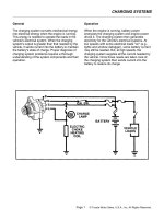
1. Insulator 2. Engine mounting bracket 3. Breather joint
4. Breather hose 5. Breather tube 6. Propeller shaft
7. Side shaft 8. Front final drive assembly
FRONT FINAL DRIVE ASSEMBLY
FFD-11
C
E
F
G
H
I
J
K
L
M
A
B
FFD
Revision; 2004 April 2003 FX
Removal and Installation (VK45DE) ADS000OE
REMOVAL
1. Remove the right bank catalytic converter. Refer to EX-3, "EXHAUST SYSTEM" .
2. Remove the stabilizer assembly. Refer to FSU-16, "STABILIZER BAR" .
3. Remove the steering gearbox mounting bolts. Refer to PS-19, "
POWER STEERING GEAR AND LINK-
AGE" .
4. Remove the front drive shaft both. Refer to FAX-12, "
FRONT DRIVE SHAFT" .
5. Remove the side shaft assembly.
6. Remove the front propeller shaft. Refer to PR-4, "
FRONT PROPELLER SHAFT" .
7. Remove the front suspension member. Refer to FSU-17, "
FRONT SUSPENSION MEMBER" .
8. Remove the engine wire harness clamp bolts from front final drive.
9. Remove the differential breather hose clamp bolt. Refer to FFD-13, "
REMOVAL AND INSTALLATION
(VK45DE)" .
10. Remove the mounting bolts and front final drive assembly from the vehicle.
INSTALLATION
Install in the reverse order of removal.
CAUTION:
● When installing side shaft, apply multi-purpose grease to contact surface of side shaft and side
shaft oil seal.
● After installation, check the final drive oil level. Refer to MA-33, "Changing Differential Gear Oil" .
SDIA2056E
1. Breather joint 2. Front final drive assembly 3. Side shaft
4. Propeller shaft 5. Breather tube 6. Breather hose
FFD-12
FRONT FINAL DRIVE ASSEMBLY
Revision; 2004 April 2003 FX
Front Final Drive Breather Hose ADS000NM
REMOVAL AND INSTALLATION (VQ35DE)
NOTE:
Refer to illustration above for front final drive breather hose routing.
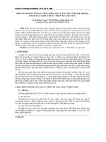
1. Breather hose 2. Breather tube 3. Front final drive assembly
4. Breather tube bracket end 5. Breather pipe bracket 6. Differential case boss
7. Machined face
SDIA1710E
FRONT FINAL DRIVE ASSEMBLY
FFD-13
C
E
F
G
H
I
J
K
L
M
A
B
FFD
Revision; 2004 April 2003 FX
REMOVAL AND INSTALLATION (VK45DE)
NOTE:
Refer to illustration above for front final drive breather hose routing.
SDIA1639E
1. Breather tube 2. Front final drive assembly 3. Breather hose
FFD-14
FRONT FINAL DRIVE ASSEMBLY
Revision; 2004 April 2003 FX
Components ADS000NB
COMPONENTS (VQ35DE)
SDIA1588E
FRONT FINAL DRIVE ASSEMBLY
FFD-15
C
E
F
G
H
I
J
K
L
M
A
B
FFD
Revision; 2004 April 2003 FX
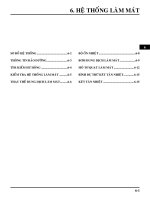
1. Washer 2. Carrier cover 3. Gear oil defence
4. Breather joint 5. Dowel pin 6. Drive pinion height adjusting washer
7. Drive pinion 8. Drive gear 9. Side bearing adjusting washer
10. Differential case 11. Side bearing 12. O-ring
13. Front oil seal 14. Side retainer 15. Side bearing adjusting shim
16. Air breather hose 17. Bushing 18. Breather tube
19. Companion flange 20. Drive pinion bearing 21. Drive pinion bearing adjusting
washer
22. Drive pinion adjusting washer 23. Extension tube retainer 24. Dust sealed
25. Side shaft 26. Extension tube 27. Carrier case
28. Side gear thrust washer 29. Lock pin 30. Pinion mate gear
31. Pinion mate thrust washer 32. Pinion mate shaft 33. Circlip
34. Side gear 35. Filler plug 36. Drain plug
37. Drive pinion lock nut 38. Side oil seal 39. Side shaft oil seal
40. Bearing
FFD-16
FRONT FINAL DRIVE ASSEMBLY
Revision; 2004 April 2003 FX
COMPONENTS (VK45DE)
1. Washer 2. Carrier cover 3. Gear oil defence
4. Breather joint 5. Dowel pin 6. Drive pinion height adjusting washer
SDIA1644E
FRONT FINAL DRIVE ASSEMBLY
FFD-17
C
E
F
G
H
I
J
K
L
M
A
B
FFD
Revision; 2004 April 2003 FX
7. Drive pinion 8. Drive gear 9. Side bearing adjusting washer
10. Differential case 11. Side bearing 12. O-ring
13. Front oil seal 14. Side retainer 15. Side bearing adjusting shim
16. Air breather hose 17. Bushing 18. Breather tube
19. Companion flange 20. Drive pinion bearing 21. Drive pinion bearing adjusting
washer
22. Drive pinion adjusting washer 23. Extension tube retainer 24. Dust sealed
25. Side shaft 26. Extension tube 27. Carrier case
28. Side gear thrust washer 29. Lock pin 30. Pinion mate gear
31. Pinion mete thrust washer 32. Pinion mate shaft 33. Circlip
34. Side gear 35. Filler plug 36. Drain plug
37. Drive pinion lock nut 38. Side oil seal 39. Side shaft oil seal
40. Bearing
FFD-18
FRONT FINAL DRIVE ASSEMBLY
Revision; 2004 April 2003 FX
Side Shaft ADS000NN
BEARING AND OIL SEAL REPLACEMENT
1. Hold the extension tube retainer with commercial service tool,
then press out the side shaft using a press.
2. Remove the side shaft oil seal from the extension tube retainer
with a flat blade screwdriver.
3. Apply multi-purpose grease to the side shaft oil seal lips, the
install it into the extension tube retainer using special service
tool.
4. Support the new bearing inner race with special service tool,
then press the side shaft into the bearing using a press.
SDIA1628E
SDIA1629E
Tool number : ST19820000 ( – )
SDIA1630E
Tool number : ST30032000 ( – )
SDIA1631E
FRONT FINAL DRIVE ASSEMBLY
FFD-19
C
E
F
G
H
I
J
K
L
M
A
B
FFD
Revision; 2004 April 2003 FX
EXTENSION TUBE REPLACEMENT
1. Drain engine oil. Refer to MA-18, "Changing Engine Oil" (VQ35DE) or MA-26, "Changing Engine Oil"
(VK45DE).
2. Ply out the extension tube from the engine oil sump.
3. Remove the O-rings from the extension tube and replace them
with new ones.
4. Apply grease to the new extension tube O-rings.
5. Install the extension tube into the engine oil sump.
PRE-DISASSEMBLY INSPECTION
Before disassembling the front final drive, perform the following inspection.
Total Preload
1. Place the front final drive onto the attachment and secure it.
2. Drain the final drive oil.
3. Remove the carrier cover.
CAUTION:
When the carrier case is damaged, replace the final drive
assembly.
SDIA1632E
SDIA1633E
SDIA1634E
SDIA1648E
FFD-20
FRONT FINAL DRIVE ASSEMBLY
Revision; 2004 April 2003 FX
4. Turn the companion flange in both direction 20 times or more to
seat the bearing rollers.
5. Check total preload with special service tool.
● If the preload value is out of standard, adjust pinion bearing
preload and side bearing preload.
Drive Gear To Drive Pinion Gear Backlash
Set the dial gauge to the drive gear face and measure the backlash.
If the measured value is out of standard, adjust the backlash by
replacing the side bearing adjusting shim (differential case side).
● If the backlash too large, decrease side bearing adjusting shim
thickness.
● If the backlash too small, increase side bearing adjusting shim
thickness.
Drive Gear Runout
1. Set dial gauge to behind the drive gear and measure the ring
gear runout.
a. If the runout is exceed limit, check for drive gear assembly:
● any object between the drive gear and differential case
● deformed differential case
● deformed drive gear
b. If drive gear is deformed, replace the drive gear and pinion gear
as a set. If the differential case is deformed, replace the differen-
tial case.
Companion Flange Runout
1. Set the dial gauge to the companion flange face and measure
runout.
2. Set the dial indicator to the inside face of the companion flange
and measure the runout.
CAUTION:
Clean inside face of companion flange before measuring
runout.
Tool number : ST3127S000 (see J25765-A)
Total preload : 1.56 - 2.65 N·m
(0.16 - 0.27 kg-m, 14 - 23 in-lb)
SDIA1649E
If the preload value too large : Decrease the drive pinion bearing adjusting washer thickness.
: Decrease the drive pinion adjusting washer thickness.
: Increase the side bearing adjusting shim thickness.
If the preload value too small : Increase the drive pinion bearing adjusting washer thickness.
: Increase the drive pinion adjusting washer thickness.
: Decrease the side bearing adjusting shim thickness.
Standard drive gear backlash
: 0.10 - 0.15 mm(0.0039 - 0.0059) in
SDIA0009J
Runout limit : 0.05 mm (0.0020 in) or less
SPD524
Runout limit : 0.18 mm (0.007 in) or less
Runout limit : 0.13 mm (0.005 in) or less
SDIA2057E
FRONT FINAL DRIVE ASSEMBLY
FFD-21
C
E
F
G
H
I
J
K
L
M
A
B
FFD
Revision; 2004 April 2003 FX
a. If runout is out side limit, remove the companion from the drive pinion. Turn the companion flange position
90° each, and measure the runout again.
b. If runout valve still out side of the limit, replace companion flange.
c. If runout valve still out side of limit after replacing companion flange, check pinion bearing and drive pinion
assembly, and pinion bearing damage.
Tooth Contact
Check tooth contact. Refer to FFD-30, "TOOTH CONTACT INSPECTION" .
DISASSEMBLY AND ASSEMBLY
Removal of Drive Gear and Differential Case Assembly
1. Remove the side retainer mounting bolt.
2. Remove the retainer by pulling it and tapping carrier case using a plastic hammer.
3. Remove the differential case assembly from the carrier case.
CAUTION:
Be careful not to damage the carrier cover mating surface.
4. Remove the side bearing outer race using puller.
5. Keep the side bearing outer races together with inner race. Do
not mix them up. Also, keep adjusting washers together with
bearings.
6. Drive out the side oil seals from the carrier case.
SDIA1656E
SDIA0181J
FFD-22
FRONT FINAL DRIVE ASSEMBLY
Revision; 2004 April 2003 FX
Removal of Drive Pinion Assembly
1. Hold the companion flange using cam sprocket wrench or flange wrench, remove the pinion lock nut.
2. Remove the companion flange using puller.
3. Temporarily install drive pinion lock nut.
CAUTION:
Install the drive pinion lock nut until it flash with the drive
pinion end.
4. Remove the drive pinion from the carrier case.
5. Remove the bearing outer race by tapping the race evenly.
6. On companion flange side, remove the bearing outer race with
bearing and oil seal.
7. Press out the drive pinion bearing from the drive pinion using
puller.
Differential Case Disassembly
1. Remove side bearing inner race.
To prevent damage to bearing, engage puller jaws in groove.
CAUTION:
● To prevent damage to the side bearing and drive gear,
place copper plates between these parts and vise.
● If is not necessary to remove side bearing except it is
replaced.
Tool number : KV40104000 ( – )
Tool number : ST30031000 (J22912–01 )
SDIA2058E
SDIA1663E
Tool number
A: ST3305S001 (J22888−20)
B: ST33061000(J8107−2)
SPD920
FRONT FINAL DRIVE ASSEMBLY
FFD-23
C
E
F
G
H
I
J
K
L
M
A
B
FFD
Revision; 2004 April 2003 FX
● Be careful not to confuse left-hand and right-hand parts.
Keep bearing and bearing race for each side together.
2. Loosen drive gear mounting bolt in a crisscross fashion.
3. Tap drive gear off the differential case with a soft hammer.
● Tap evenly all around to keep the drive gear from binding.
4. Disassembly the differential case.
a. Drive out the pinion mate shaft lock pin using punch.
b. Remove the pinion mate shaft.
c. Turn the pinion mate gear, then remove the pinion mate gear,
pinion mate thrust washer, side gear and side gear thrust
washer from the differential case.
SPD022
SDIA0246J
Tool number : KV31100300 ( – )
SDIA1664E
SDIA0031J
SDIA0032J
FFD-24
FRONT FINAL DRIVE ASSEMBLY
Revision; 2004 April 2003 FX
d. Check mating surfaces of differential case, side gears, pinion
mate gears, pinion mate shaft and thrust washers.
Inspection
● Clean up the disassemble parts. Then, inspect if the parts are wear or damaged. If so, follow the mea-
sures below.
Differential Case Assembly ADS000NO
1. Apply gear oil to contact surfaces of each gear, thrust washers
and differential case.
2. Install the removed thrust washer or same thickness washer to
side gear.
SDIA0187J
Content Measures
Drive gear and drive pinion
● If the gear teeth do not mesh or line-up correctly, determine the cause and
adjust, repair, or replace as necessary.
● If the gear are worn, cracked, damaged, pitted or chipped (by friction)
noticeably, replace with new gears.
Bearing
● If found any chipped (by friction), pitted, worn, rusted, scratched mark, or
unusual noise from the bearing, replace with new bearing assembly (as a
new set).
Side gear and pinion mate gear
● Replace with a new one if found any cracks or damage on the surface of
the tooth.
● Replace with a new one if found any worn or chipped mark on the contact
sides of the thrust washer.
Side gear thrust washer and pinion mate thrust washer
● Replace with a new one if found that it is chipped (by friction), damaged, or
unusual worn.
Oil seal
● Oil seals must be replaced with a new one whenever disassembled.
Differential case
● Replace with a new one if found any wear or cracks on the contact sides of
the differential case.
Companion flange
● Replace with a new one if found any chipped marks (about 0.10 mm,
0.0038 in) or other damage on the contact sides of the lip of the companion
flange.
SDIA0193J
FRONT FINAL DRIVE ASSEMBLY
FFD-25
C
E
F
G
H
I
J
K
L
M
A
B
FFD
Revision; 2004 April 2003 FX
3. Install the side gear, thrust washers, pinion mate gears and
thrust washers to differential case.
CAUTION:
Install the circlip equipped side gear to the side retainer
side.
4. Install pinion mate gears by placing the pair of gear facing each
other, and turning them.
5. Install the pinion mate shaft while aligning the lock pin holes
between the differential case and pinion mate shaft.
6. Place the differential gear case so that measurement point fac-
ing up as shown.
7. Use two feeler gauges to prevent leaning of side gear as shown.
8. Measure the clearance at 3 points by turning the side gear.
9. Select side gear thrust washer so that the clearance is within
standard.
CAUTION:
Check the smooth gear movement.
10. Place the differential gear case upside down, and measure the
opposite side clearance.
SDIA0194J
SDIA0195J
SDIA1650E
Rear face of side gear and differential case clearance
: 0.20 mm (0.0079 in) or less
SDIA1654E
SDIA1655E