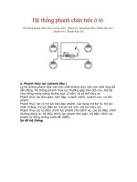
PB hệ THỐNG THẮNG CHÂN TRÊN INFINITI FX35, FX45 2003
Bạn đang xem bản rút gọn của tài liệu. Xem và tải ngay bản đầy đủ của tài liệu tại đây (220.08 KB, 8 trang )
PB-1
PARKING BRAKE SYSTEM
F BRAKES
CONTENTS
C
D
E
G
H
I
J
K
L
M
SECTION PB
A
B
PB
Revision; 2004 April 2003 FX
PARKING BRAKE SYSTEM
PARKING BRAKE SYSTEM 2
On-Vehicle Service 2
PEDAL STROKE 2
INSPECT COMPONENTS 2
ADJUSTMENT 2
PARKING BRAKE CONTROL 3
Components 3
Removal and Installation 3
REMOVAL 3
INSTALLATION 4
PARKING BRAKE SHOE 5
Components 5
Removal and Installation 5
REMOVAL 5
INSPECTION AFTER REMOVAL 6
INSTALLATION 6
SERVICE DATA AND SPECIFICATIONS (SDS) 7
Parking Drum Brake 7
Parking Brake Control 7
PB-2
PARKING BRAKE SYSTEM
Revision; 2004 April 2003 FX
PARKING BRAKE SYSTEM PFP:36010
On-Vehicle Service AFS001TJ
PEDAL STROKE
● When parking brake pedal is operated with a force of 200 N (20.4 kg, 44.9 lb), make sure the stroke is
within the specified number of notches. (Check it by listening and counting the ratchet clicks.)
INSPECT COMPONENTS
● Make sure the components are attached properly (check for looseness, backlash, etc.).
● Check parking brake pedal assembly for bend, damage and cracks, and replace if necessary.
● Check cable for wear and damage, and replace if necessary.
● Check parking brake warning lamp switch for malfunction, and replace if necessary.
ADJUSTMENT
● To perform adjustment operations, remove tire from the vehicle with power tool.
1. Insert a deep socket wrench to rotate adjusting nut and loosen
cable sufficiently. Then, return pedal.
2. Using wheel nuts, fix disc to hub and prevent it from tilting.
3. Remove adjusting hole plug installed on disc. Using a screw-
driver, turn Adjuster in direction A as shown in the figure until
disc rotor is locked. After locking, turn adjuster in the opposite
direction by 5 or 6 notches.
4. Rotate disc rotor to make sure there is no drag. Install adjusting
hole plug.
5. Adjust cable as follows:
a. Operate pedal 10 or more times with a force of 490 N (50 kg,
110 lb).
b. Rotate adjusting nut with deep socket to adjust pedal stroke.
CAUTION:
Do not reuse adjusting nut after removing it.
c. When parking brake pedal is operated with a force of 200 N (20.4 kg, 44.9 lb), make sure the stroke is
within the specified number of notches. (Check it by listening and counting the ratchet clicks.)
d. With pedal completely returned, make sure there is no drag on rear brake.
Pedal stroke : 4 − 5 notches
SFIA1139E
Pedal stroke : 4 − 5 notches
PFIA0295E
PARKING BRAKE CONTROL
PB-3
C
D
E
G
H
I
J
K
L
M
A
B
PB
Revision; 2004 April 2003 FX
PARKING BRAKE CONTROL PFP:36010
Components AFS001TK
Removal and Installation AFS001TL
REMOVAL
1. Remove front kick plate (driver side). Refer to IP-12, "(A) Front Kicking Plate (LH/RH)" .
2. Remove front body side welt (driver side). Refer to EI-37, "
BODY SIDE TRIM" .
3. Remove dash side finisher (driver side). Refer to IP-10, "
INSTRUMENT PANEL ASSEMBLY" .
4. Remove instrument lower panel (driver side). Refer to IP-10, "
INSTRUMENT PANEL ASSEMBLY" .
5. Remove adjusting nut.
6. Remove front cable installation bolt, nut and remove front cable from the vehicle.
7. Remove heat insulator between center tube and rear propeller shaft.
8. Remove exhaust center tube. Refer to EX-3, "
EXHAUST SYSTEM" .
9. Remove propeller shaft. Refer to PR-8, "
Removal and Installation" .
10. Remove rear disc caliper and disc rotors. Refer to BR-26, "
Removal and Installation of Brake Caliper
Assembly" .
11. Remove parking brake shoe, and remove rear cable from toggle lever. Refer to PB-5, "
PARKING BRAKE
SHOE" .
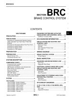
1. Device assembly 2. Spring insulator 3. Return spring
4. Lock plate 5. Front cable 6. Return spring
7. Rear right cable 8. Rear left cable 9. Pin
10. Adjusting nut
SFIA1138E
PB-4
PARKING BRAKE CONTROL
Revision; 2004 April 2003 FX
12. Remove right and left rear cables installation nut, bolt, and remove right and left rear cable assembly from
the vehicle.
INSTALLATION
1. Refer to “Components” for tightening torque. Install in the reverse order of removal.
CAUTION:
Do not reuse adjusting nut after removing it.
2. Adjust parking brake. Refer to PB-2, "
ADJUSTMENT" .
PARKING BRAKE SHOE
PB-5
C
D
E
G
H
I
J
K
L
M
A
B
PB
Revision; 2004 April 2003 FX
PARKING BRAKE SHOE PFP:44060
Components AFS001TM
Removal and Installation AFS001TN
REMOVAL
WARNING:
Clean brakes with a vacuum dust collector to minimize the hazard of airborne particles or other mate-
rials.
Be careful of the following:
● Remove disc rotor only with parking brake pedal completely in the returned position.
● If disc rotor cannot be removed, remove as follows.
1. Fix disc rotor in place with wheel nuts and remove disc rotor
plug. Using a screwdriver, rotate adjuster on adjuster assembly
in direction B to retract and loosen brake shoes.
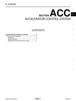
1. Back plate 2. Anchor block 3. Toggle lever
4. shoe 5. Adjuster 6. Return spring
7. Anti-rattle spring 8. Retainer 9. Anti-rattle pin
SFIA1167E
PFIA0309E
PB-6
PARKING BRAKE SHOE
Revision; 2004 April 2003 FX
INSPECTION AFTER REMOVAL
Lining Thickness Inspection
● Check thickness of lining.
Drum Inner Diameter Inspection
● Check drum inner diameter.
Other Inspections
● Check shoe sliding surface for excessive wear and damage.
● Check anti-rattle pin for excessive wear and corrosion.
● Check return spring for sagging.
● Check adjustor for rough operation.
● Check either visually or with a vernier caliper to see if there is
any excessive wear, cracks, or damage inside drum.
INSTALLATION
Be careful of the following:
● Refer to “Component Parts Location” and apply brake grease to the specified points during assembly.
● Assemble adjuster so that threaded part expands when rotating
it in the direction shown by the arrow.
● Shorten adjuster by rotating it.
● When disassembling adjuster, apply PBC (Poly Butyl Cuprysil)
grease or silicone based grease to the threads.
● After replacing brake shoes or disc rotors, or if brakes do not
function well, perform break-in operation as follows.
1. Adjust parking brake pedal stroke to the specified stroke.
2. Perform parking brake break-in (drag run) operation by driving
the vehicle under the following conditions:
3. After break-in operation, check lever stroke of parking brake. Readjust if it is no longer at the specified
stroke.
● To prevent lining from getting too hot, allow a cool off period of approximately 5 minutes after every
break-in operation.
● Do not perform excessive break-in operations, because it may cause uneven or early wear of lining.
Standard thickness (A) : 3.2 mm (0.126 in)
Repair limit thickness (A) : 1.5 mm (0.059 in)
SBR021A
Standard inner diameter : 190 mm (7.48 in)
Maximum inner diameter : 191 mm (7.52 in)
SBR768A
Drive forward
● Vehicle speed approx. 40 km/h (25 MPH) set (forward)
● Parking brake operating force approx. 200 N (20.4 kg, 44.9 lb) set
● Time approx. 30 sec.
SFIA0153E
SERVICE DATA AND SPECIFICATIONS (SDS)
PB-7
C
D
E
G
H
I
J
K
L
M
A
B
PB
Revision; 2004 April 2003 FX
SERVICE DATA AND SPECIFICATIONS (SDS) PFP:00030
Parking Drum Brake AFS001TO
Parking Brake Control AFS001TP
Type DS19HC
Brake lining
Standard thickness (new) 3.2 mm (0.126 in)
Wear limit thickness 1.5 mm (0.059 in)
Drum (disc)
Standard inner diameter (new) 190 mm (7.48 in)
Wear limit of inner diameter 191 mm (7.52 in)
Control type Foot pedal
Number of notches [under force of 200 N (20.4 kg, 44.9 lb)] 4 − 5 notches
Number of notches
when warning lamp switch comes on
1 notches
PB-8
SERVICE DATA AND SPECIFICATIONS (SDS)
Revision; 2004 April 2003 FX