cirstea, m. n. (2002). neural and fuzzy logic control of drives and power systemsl
Bạn đang xem bản rút gọn của tài liệu. Xem và tải ngay bản đầy đủ của tài liệu tại đây (2.4 MB, 408 trang )
Neural and Fuzzy Logic Control
of Drives and Power Systems
Neural and Fuzzy Logic
Control of Drives and
Power Systems
M.N. Cirstea, A. Dinu, J.G. Khor,
M. McCormick
Newnes
OXFORD AMSTERDAM BOSTON LONDON NEW YORK PARIS
SAN DIEGO SAN FRANCISCO SINGAPORE SYDNEY TOKYO
Newnes
An imprint of Elsevier Science
Linacre House, Jordan Hill, Oxford OX2 8DP
225 Wildwood Avenue, Woburn, MA 01801-2041
First published 2002
Copyright © 2002, M.N. Cirstea, A. Dinu, J.G. Khor, M. McCormick. All rights reserved
The right of M.N. Cirstea, A. Dinu, J.G. Khor and M. McCormick to be identified as the
authors of this work has been asserted in accordance with the Copyright,
Designs and Patents Act 1988
No part of this publication may be reproduced in any material form (including
photocopying or storing in any medium by electronic means and whether
or not transiently or incidentally to some other use of this publication) without
the written permission of the copyright holder except in accordance with the
provisions of the Copyright, Designs and Patents Act 1988 or under the terms of
a licence issued by the Copyright Licensing Agency Ltd, 90 Tottenham Court Road,
London, England W1T 4LP. Applications for the copyright holder’s written
permission to reproduce any part of this publication should be addressed
to the publisher
British Library Cataloguing in Publication Data
A catalogue record for this book is available from the British Library
ISBN 0 7506 55585
For information on all Newnes publications
visit our website at www.newnespress.com
Typeset at Replika Press Pvt Ltd, Delhi 110 040, India
Printed and bound in Great Britain
Preface
Control systems 1
Control theory: historical review 1
Introduction to control systems 2
Control systems for a. c. drives 5
Modern control systems design using
CAD techniques
Electronic design automation ( EDA)
Application specific integrated circuit (
ASIC) basics 12
Field programmable gate arrays (
FPGAs) 14
ASICs for power systems and drives 16
Electric motors and power systems
Electric motors
Power systems 19
Pulse width modulation 22
The space vector in electrical systems 26
Induction motor control 28
Synchronous generators control 51
Elements of neural control
Neurone types
Artificial neural networks architectures 59
Training algorithms 61
Control applications of ANNs 69
Neural network implementation 71
Neural FPGA implementation
Neural networks design and
implementation strategy
Universal programs FFANN
hardware implementation 95
Hardware implementation complexity
analysis 98
Fuzzy logic fundamentals
Historical review
Fuzzy sets and fuzzy logic 114
Types of membership functions 116
Linguistic variables 117
Fuzzy logic operators 117
Fuzzy control systems 118
Fuzzy logic in power and control
applications 121
VHDL fundamentals
Introduction
VHDL design units 126
Libraries, visibility and state system in
VHDL 131
Sequential statements 135
Concurrent statements 141
Functions and procedures 146
Advanced features in VHDL 151
Summary 154
Neural current and speed control of
induction motors
The induction motor equivalent circuit
The current control algorithm 161
The new sensorless motor control
strategy 183
Induction motor controller VHDL
design 199
FPGA controller experimental results 227
Fuzzy logic control of a synchronous
generator set
System representation
VHDL modelling 248
FPGA implementation 270
System assembly and experimental
tests 285
Conclusions 292
Final notes
References
Appendices
Appendix A - C++ code for ANN
implementation
Appendix B - C++ Programs for PWM
generation 333
Appendix C - Subnetworks VHDL
models 341
Appendix D - VHDL model of sine
wave ROM 355
Appendix E - VHDL code for
simulation 357
Appendix F - VHDL code for synthesis 374
Appendix G - PWM controllers 389
Index
Preface
The idea of writing this book arose from the need to investigate the main principles of
modern power electronic control strategies, using fuzzy logic and neural networks, for
research and teaching. Primarily, the book aims to be a quick learning guide for
postgraduate/undergraduate students or design engineers interested in learning the
fundamentals of modern control of drives and power systems in conjunction with the
powerful design methodology based on VHDL.
At the same time, the book is structured to address the more complex needs of
professional designers, using VHDL for neural and fuzzy logic systems design, by
including comprehensive design examples. This facilitates the understanding of hardware
description language applications and provides a practical approach to the development
of advanced controllers for power electronics.
The first section of the book contains a brief review of control strategies for electric
drives/power systems and a summary description of neural networks, fuzzy logic, electronic
design automation (EDA) techniques, ASICs/FPGAs and VHDL. The aspects covered
allow a basic understanding of the main principles of modern control. The second
section contains two comprehensive case studies. The first deals with neural current and
speed control of induction motor drives, whereas the second presents the environmentally
friendly fuzzy logic control of a diesel-driven stand-alone synchronous generator set.
Both control strategies were implemented in Xilinx FPGAs and comprehensively tested
by simulation and experimental measurements.
This book brings together the complex features of control strategies, EDA, neural
networks, fuzzy logic, electric machines and drives, power systems and VHDL and
forms a basic guide for the understanding of the fundamental principles of modern
power electronic control systems design. To be expert in the design of advanced digital
controllers for drives and power systems, extra reading is strongly recommended and
comprehensive material is referenced in the bibliographical section. The book includes
a number of recent research results from work carried out by the authors, who are
members of the electronic control and drives research group at De Montfort University,
Leicester, UK.
The facilities provided by the university and the support of NEWAGE AVK SEG,
Stamford, UK, a major international manufacturer of electric generators, are gratefully
acknowledged.
Dr Marcian N. Cirstea
Dr Andrei Dinu
Dr Jeen G. Khor
Prof. Malcolm McCormick
1
Control systems
1.1 Control theory: historical review
The function of a control mechanism is to maintain certain essential properties of a
system at a desired value under perturbations. Historical control systems which are
simple but effective have been employed in water regulation and control of liquid level
in wine vessels for centuries. Some of these concepts are still used today, for example
the float system in the water tank of the toilet flush. However, modern control systems
used in today’s industry are much more complex and owe their beginnings to the
development of control theory. The earliest significant work in modern automatic control
can be traced to James Watt’s design of the fly-ball governor (1788) for the speed
control of a steam engine. In 1868, Maxwell [170] presented the first mathematical
analysis of feedback control. It was during this time that systematic studies into control
systems and feedback dynamics began. One significant development was the well-
known Routh’s stability criterion (1877) which won E.J. Routh the Adam’s Prize.
The early twentieth century saw the beginning of what is now known as classical
control theory. Minorsky’s work (1922) on the determination of stability from the
differential equation describing the system (characteristic equation) and Nyquist’s
development (1932) of a graphical procedure for determining stability (frequency response)
substantially contributed to the study of control theory. In 1934, Hazen [111] introduced
the term ‘servomechanism’ to describe position control systems in his attempt to develop
a generalised theory of servomechanisms. Two years later, the development of the
proportional integral derivative (PID) controller was described by Callender et al.
(1936). Control theory, like many branches of engineering, underwent significant
development during World War II. Based on Nyquist’s work, H.W. Bode introduced a
method for feedback amplifier design, now known as the Bode plot (1945). By 1948, the
root locus method of design and stability analysis was developed by W.R. Evans [93].
With the introduction of digital computers in the 1960s, the use of frequency response
and characteristic equations began to give way to ordinary differential equations (ODEs),
which worked well with computers. This led to the birth of modern control theory.
While the term classical control theory is used to describe the design methods of
Bode, Nyquist, Minorsky and similar workers, modern control theory relies on ODE
design methods that are more suitable for computer aided engineering, for example the
state space approach. Both these branches of control theory rely on mathematical
representation of the control plant from which to derive its performance. To address the
issues of non-linearities and time-variant parameters in plant models, control strategies
2 Neural and Fuzzy Logic Control of Drives and Power Systems
that continuously adapt to the variations of plant characteristics have been introduced.
Generally known as adaptive control systems, they include techniques such as self-
tuning control, H-infinity control, model referencing adaptive control and sliding mode
control, Studies also include the use of non-linear state observers that continuously
estimate the parameters of the control plant [174]. They can be employed to tackle the
issue of non-observability, that is the condition whereby not all of the required states are
available for feedback. This may be the cheaper solution because it does not require as
many sensors, such as in variable speed drives [59], or because it is physically difficult
or even impossible to obtain the feedback states such as in a nuclear reactor.
In many instances, the mathematical model of the plant is simply unknown or ill-
defined, leading to greater complexities in the design of the control system. It has been
proposed that intelligent control systems give a better performance in such cases.
Unlike conventional control techniques, intelligent controllers are based on artificial
intelligence (AI) rather than on a plant model. They imitate the human decision-making
process and can often be implemented in complex systems with more success than
conventional control techniques. AI can be classified into expert systems, fuzzy logic,
artificial neural networks and genetic algorithms. With the exception of expert systems,
these techniques are based on soft-computing methods. The result is that they are capable
of making approximations and ‘intelligent guesses’ where necessary, in order to come
out with a ‘good enough’ result under a given set of constraints. Intelligent control
systems may employ one or more AI techniques in their design.
1.2 Introduction to control systems
A system is a group of physical components assembled to perform a specific function.
A system may be electrical, mechanical, hydraulic, pneumatic, thermal, biomedical, or
a combination of any of these systems. An ideal control system is one in which an output
is a direct function of input. However, in practice disturbances affect the output being
controlled and cause it to deviate from the desired value. A control system may be
defined in a variety of ways, but the most basic definition is:
A control system is a group of components assembled in such a way as to regulate an
energy input to achieve the desired output.
1.2.1 Classification
Control systems are classified based on the following characteristics:
(A) The type of operating techniques used in driving the output to a desired value:
• Analogue control systems – analogue techniques are used to process the input
signal and control the output signal.
• Digital control systems – digital techniques are employed to control the output.
Analogue, digital, or both analogue and digital techniques may be used to
control a desired physical quantity, which can be any physical variable (tempera-
ture, pressure, electric voltage, mechanical position, etc.). At the beginning
Control systems 3
of the control era, most control systems were analogue employing analogue
techniques, but these systems were relatively bulky, complex and cumbersome,
both to design and to maintain. However, with the development of digital
technology the design of control systems became easier as well as more
economical. Nowadays, digital control systems are used more and more due to
their accuracy, precision, high speed of response, wide range of applications
and, why not, elegance. The main difference between an analogue control system
and a digital control system is that the first processes continuous signals while
the second processes discrete signals, which are in fact periodically taken samples
of continuous signals.
(B) The use of feedback:
• Closed-loop systems with either positive (regenerative) feedback or negative
(degenerative) feedback. If an output or part of an output is fed back so that it
can be compared with an input, the system is said to use feedback and the
arrangement forms a closed loop. If the feedback signal aids an input signal –
the feedback is positive; if the feedback signal opposes the input signal – the
feedback is negative.
• Open-loop systems – systems that don’t use a feedback. Advantages of open-
loop control systems are that they are relatively simple, economical and easy to
maintain. On the other hand, closed-loop systems are more accurate, stable and
less sensitive to outside disturbances, although they are relatively expensive,
complex and not easy to maintain.
(C) The nature of system behaviour:
• Linear systems – if the amplitude proportionality property (a) and the principle
of superposition (b) are satisfied. (a) If the system output is o(t) for a given
input i(t), then for an input K
i
(t) the output should be K
o
(t); K is the proportionality
constant. (b) According to the superposition principle if i
1
(t) and i
2
(t) are inputs
and their corresponding outputs are o
1
(t) and o
2
(t), then the input i
1
(t) + i
2
(t)
must produce the output o
1
(t) + o
2
(t). Example d.c. motor speed control system.
• Non-linear systems – these do not follow amplitude proportionality and the
superposition principle.
(D) The application area:
• Servomechanisms – control systems in which the output or the controlled variable
is a mechanical position or the rate of change of mechanical position (a motion).
Example: d.c. motor speed control.
• Sequential control systems – systems in which a prescribed set of operations are
performed. Example: automatic washing machine.
• Numerical control systems – they act on ‘numerical information’ (controlled
variables as position, speed, direction – coded in the form of instructions)
stored on a ‘control medium’ (simply a storage medium: punched cards, paper
tape, magnetic tape, CD-ROM). The control medium contains all the instructions
necessary to accomplish a desired manufacturing operation (milling, welding,
drilling). The major advantage of a numerical control system is the flexibility
of its control medium.
• Process control systems – the variables in a manufacturing process are controlled.
Examples: temperature, pressure, conductivity. They can be either closed-loop
or open-loop control systems.
4 Neural and Fuzzy Logic Control of Drives and Power Systems
(E) The method of generating the control pulses:
• Single-channel control systems.
• Multi-channel control systems.
(F) The synchronisation between the signals within the control system and input
voltages:
• Synchronous control systems.
• Asynchronous control systems.
1.2.2 Characteristics of control systems
Although different systems are designed to perform different functions, all of them have
to meet some common requirements. The major characteristics of a typical control
system, which are often used as measures of performance to evaluate a system under
consideration, are the following:
1.2.2.1 Stability
A system is said to be stable if its output attains a certain value in a finite time after the
input is applied. When the output of a system remains constant and does not change as
a function of time, the output is said to attain a steady-state value. On the contrary, an
unstable system never attains a steady-state value. A practical system must be stable. An
unstable system may be made stable by using certain techniques, of which the most
common is the use of compensating networks. Often, an unstable system is made stable
simply by using negative feedback.
1.2.2.2 Accuracy
The accuracy indicates deviation of the actual output from its desired value and it is a
relative measure of system performance. Generally, the accuracy of a control system is
improved by using control models such as integral or integral plus proportional.
1.2.2.3 Speed of response
The speed of response is a measure of how quickly an output attains a steady-state value
after the input is applied. A practical system must have a finite response time.
1.2.2.4 Sensitivity
The sensitivity of a system is a measure of how sensitive the output is to changes in the
values of physical components as well as environmental conditions. The dependence of
output on disturbances can be minimised by using certain compensating networks.
1.2.2.5 Representation
The most common methods used to represent control systems in order to improve
communication between design engineers and users are block diagrams and signal flow
graphs. They help visualisation of the system under consideration at a glance. The block
diagram of a system consists of blocks, directed line segments joining these blocks and
the summing junctions or error detectors that are used to add the signals algebraically.
Control systems 5
A signal flow graph is a diagram that indicates the manner in which the signal flows in
a given system. It is a one-line diagram that uses directed segments.
This short overview on control systems and their general features aimed to familiarise
the reader with basic characteristics of control systems. The next section focuses on
some general aspects of control systems for electrical drives, especially for a.c. electrical
drives.
1.3 Control systems for a.c. drives
A specific definition of a process control system may be: ‘A control system is a combination
of amplifiers, transducers, and actuators, which collectively act on a process to maintain
some condition at a required value.’ The adjustable speed a.c. drive constitutes a
multivariable control system and therefore, in principle, the general theories of multivariable
control system should be applicable. Here, the voltages and the frequency are the control
inputs and the outputs may be speed, position, torque, airgap flux, stator current or a
combination of all of them. If the mathematical model of the system is considered
precise and no extraneous disturbances are possible, then theoretically open loop control
of the drive system should be satisfactory. This means that the control functions can be
defined uniquely to give the specified performance of the drive system. The performance
of the drive can be optimised by generating critical control functions using modern
optimal control theories. Optimal control theory is extremely difficult to apply to a real
life industrial drive system because of the laborious computational requirement and the
inaccuracies of the system model.
1.3.1 The objects of control systems in a.c. drives
Before the advent of power semiconductor devices, a.c. machines were commonly
accepted as fixed speed machines due to their connection to a fixed voltage and frequency
supply. Similarly, d.c. motors were considered the workhorses in industry for variable
speed applications. Although control principles and converter equipment are simple, the
d.c. machine is expensive when compared to the simple and rugged cage type induction
motor. In addition, the principal problem of a d.c. machine is that commutators and
brushes make it unreliable, unsuitable to operate in dusty and explosive environments
and it requires frequent maintenance. The a.c. machine is more rugged and reliable, as
well as less expensive and more efficient, especially the cage type induction motor;
however, the cost of the converter and the control is considerably higher, which makes
the a.c. drive more expensive than the d.c. drive. In addition, the control of a.c. drives
is very complex and requires intricate signal processing to obtain a performance comparable
to the d.c. drive. Present technology aims to provide substantial cost reductions and
performance improvements for a.c. drive systems to make them more universally used.
Some of the expanding application areas are:
• Replacement of variable speed d.c. drives by appropriate a.c. drive systems.
• Application of adjustable speed a.c. drives to constant speed process control, thereby
saving energy.
6 Neural and Fuzzy Logic Control of Drives and Power Systems
• Replacement of heat engines (which use petroleum-based energy), hydraulic and
pneumatic controlled drive systems by electric a.c. drive systems (as in the electric
car).
An electrical a.c. machine is a complex electromagnetic and mechanical structure that
is designed for optimal conversion of electrical energy into mechanical energy, and vice
versa. In a conventional multiphase machine, the time phase distribution of power
supply and space phase distribution of stator windings produce a rotating airgap flux
wave, and the speed of rotation correlates with the frequency of the power supply. The
airgap flux reacts with the rotor magnetomotive force (MMF) wave to develop the
electrical torque, the magnitude of which depends on the flux and MMF amplitudes and
their phase displacement angle. The rotor MMF in a synchronous machine is created by
a separate field winding that carries d.c. current, whereas in an induction motor it is
produced by the stator induction effect. The speed to frequency relationship is unique in
a synchronous machine, but for induction motors, the rotor must ‘slip’ from synchronous
speed to induce rotor MMF, which results in the development of the torque.
In adjustable speed a.c. drive systems the static power converter constitutes an interface
between the primary power supply and the machine. The converter generally converts
and controls the 60 Hz, three-phase a.c. supply for the machine, which may be at
variable-voltage-constant-frequency, constant-voltage-variable-frequency or variable-
voltage-variable-frequency. A converter consists of a matrix of power semiconductor
switching devices which may be thyristors, gate turn-off (GTO) devices, power transistors,
or power MOS. This acts like a switch mode power amplifier between the control
signals and the output, with inherently rich harmonics at the input and the output. The
output harmonics cause machine heating and torque pulsation problems and the input
harmonics cause line voltage distortion and electromagnetic interference (EMI) problems.
Since generally no additional dynamics are involved in the converter circuit, the input
and output powers match at any instant, and the output waveform may be constructed
from input waves and the characteristic switching functions.
A well-designed drive system should carefully consider the interaction between the
converter and the machine, and the various design trade-off considerations. As the
converter operation and its mode of control severely affect the machine performance,
the machine parameters similarly affect the converter performance. The power switching
devices of a converter are delicate and very sensitive to voltage and current transients.
While a machine may have large overload current capability, the semiconductor device
overload capability is very limited because of the short transient thermal time constant.
In addition, the commutation capability of a converter may soon reach the limiting
condition due to overcurrent. Therefore, the converter is normally designed to match the
peak power capability of the machine, which is an expensive proposition. Because of the
possibility of overvoltage and overcurrent failures, a converter normally requires well-
designed control and protection schemes.
1.3.2 Basic principle of microcomputer control
Traditional control systems are normally implemented using analogue and digital hardware.
In its relatively short existence, digital computer technology has touched, and had a
profound effect upon, many areas of life. Its enormous success is due largely to the
Control systems 7
flexibility and reliability that computer systems offer to potential users. This, coupled
with the ability to handle and manipulate vast amounts of data quickly, efficiently and
repeatedly, has made computers extremely useful in many varied applications. In control
systems the digital computer acts as the controller and provides the enabling technology
that allows the design and implementation of the overall system, so that satisfactory
performance is obtained.
Digital control systems differ from continuous systems in that the computer acts only
at instants of time rather than continuously. This is because a computer can execute only
one operation at a time, and so the overall algorithm proceeds in a sequential manner.
Hence, taking measurements from the system and processing them to compute an activating
signal, which is then applied to the system, is a standard procedure in a typical control
application. Having applied a control action, the computer collects the next set of
measurements and repeats the complete iteration in an endless loop. The maximum
frequency of control update is defined by the time taken to complete one cycle of the
loop. This is obviously dependent upon the complexity of the control task and the
capabilities of the hardware.
At first glance this appears to be a poorly matched situation, where a digital computer
is attempting to control a continuous system by applying impulsive signals to it every
now and then; from this viewpoint it seems unlikely that satisfactory results are possible.
Fortunately, the setup is not as awkward as it first appears. If the cycle iteration speed
of the computer and the dynamics of the system are taken into account, adequate
performance can be expected when the former is much faster than the latter. Indeed,
digital controllers have been used to give results as good as, or better than, analogue
controllers in numerous situations, with the added feature that the control strategies can
be varied by simply reprogramming the computer instead of having to change the
hardware. In addition, analogue controllers are susceptible to ageing and drift, which in
turn causes degradation in performance. These advantages have attracted many users to
adopt digital technology in preference to conventional methods and made computer
control applicable to many areas. Some of the current interest areas are: auto-pilots for
aeroplanes/missiles, satellite altitude control, industrial and process control, robotics,
navigational systems and radar and building energy management and control systems.
With advances in VLSI (very large scale integration) and denser packing capabilities,
faster integrated circuits can be manufactured which result in quicker and more powerful
computers. Therefore, application to control areas which a few years ago were considered
to be impractical or impossible because of computer limitations, are now entering the
realms of possibility.
Another recent advance in computer systems is in the area of parallel processing,
where the computational task is shared out between several processors that can
communicate with each other in an efficient manner. Individual processors can solve
sub-problems, with the results brought together in some ordered way, to arrive at the
solution to the overall problem. Since many processors can be incorporated to execute
the computations, it is possible to solve large and complex problems quickly and efficiently.
One of the problems in a computer control system is the interfacing between computers
and continuous systems so that the analogue plant signals can first be read into the
computer, and then digital control signals can be applied to the system. Analogue
signals must be converted into digital form for analysis in the computer, and the digital
signals from the computer have to be converted back to analogue form for application
8 Neural and Fuzzy Logic Control of Drives and Power Systems
to the plant under control. This kind of converter can introduce significant conversion
time delays into digital computer control system applications. These, together with
other sequential processing delays, mean that when continuous analogue signals are to
be converted into digital form, the conversions can only be performed at discrete instants,
separated by finite intervals.
In computer control applications impulsive signals are inappropriate for controlling
analogue systems, since these require an input signal to be present all the time. To
overcome this difficulty, hold devices are inserted at the digital-to-analogue interfaces.
The simplest device available is a zero-order-hold (ZOH), which holds the output constant
at the value fed to it at the last sampling instant; hence a piecewise constant signal is
generated. Higher order holds are also available, which use a number of previous sampling
instant values to generate the signal over the current sampling interval.
Mainly, in a digital control loop, the following procedure must take place:
• Measure system output and compare with the desired value to give an error.
• Use the error, via a control law, to compute an actuating signal.
• Apply this corrective input to the system.
• Wait for the next sampling instant.
• Repeat this algorithm.
The functions that can be incorporated in microcomputer software are summarised as
follows:
• Converter control, including firing pulse generation.
• Feedback control.
• Signal estimation for system control.
• Drive mode sequencing.
• Diagnostics.
The superiority of microcomputer control over conventional hardware-based control
can be recognised as evident when dealing with complex drive control systems. The
simplification of hardware saves control electronics cost and improves the system reliability.
Digital control has inherently improved noise immunity, which is particularly important
in drive systems because of large power switching transients in the converters. Additionally,
the software control algorithms can easily be altered or improved in the future without
changing the hardware. Another important feature is that the structure and parameters of
the control system can be altered in real time, making the control adaptive to the plant
characteristics. The complex computation and decision-taking capabilities of micro-
computers enables the application of the modern optimal and adaptive control theories
to optimise the drive system performance. In addition, powerful diagnoses can be written
in the software. Microcomputer technology is moving at such a fast rate that the use of
efficient high level language with large hardware integration and VLSI implementation
of the controller is easily possible.
Unlike dedicated hardware control, a microcomputer executes control in serial fashion,
i.e. multitasking operations are performed in a time multiplexed method. As a result, a
slow computation capability may pose serious problems in executing the fast control
loops. However, the problem can be solved by multi-microprocessor control, where
judicious partitioning of tasks can significantly enhance the execution speed. The different
stages necessary in microcomputer control development of a drive system are:
Control systems 9
• Develop control strategy.
• Make simplified system study and determine control parameters.
• Translate into digital control algorithm.
• Simulate drive system on hybrid/digital computer-iterate control.
• Develop hardware and software.
• Design and build breadboard test.
The foregoing outlines some basic aspects of microcomputer/microprocessor control.
Presently, many digital control systems are microprocessor-based, primarily because of
the availability of control integrated circuits (ICs), cheaper memories and tremendous
advancements in data handling capabilities. A big step forward in control is the use of
application specific integrated circuits (ASICs), which have successfully replaced
microprocessors due to their ease of design using modern computer-aided design (CAD)/
electronic design automation (EDA) techniques.
2.1 Electronic design automation (EDA)
Following the traditional design route, the engineer begins with the idea, then normally
proceeds to the paper circuit design stage. The design then continues through to the
prototype stage, using any of the many traditional construction methods. The prototype
design is then tested and verified against the specification. At this point if any conceptual
fault is found, a redesign is carried out and the process is repeated.
The use and simulation of mathematical models for electrical systems design has
been employed for some considerable time, but the functional models derived must then
be translated into hardware and it is at this stage that the technology-based design rules
and delays are taken into account. Electronic design automation (EDA) enables this
transition to take place with a higher degree of confidence than was previously possible.
EDA tools are well suited to providing low level, high speed hardware, to implement
the control functions in power electronic systems. Computer-aided design (CAD) software
enables the design and evaluation of these complex digital circuits within the PC/
workstation environment, without the requirement for physical hardware at this stage.
For the successful development of the specialised microelectronics hardware needed, a
knowledge of available technologies and EDA techniques for design, simulation, layout,
PCB production and verification is required. The design cycle can be considerably
reduced by removing three parts of the design cycle before the design is verified, by a
technique known as the modelling and simulation method. This allows a product to be
produced for the market in a much shorter time than using traditional methods. The
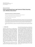
method is illustrated in the block diagram in Fig. 2.1.
The method allows the development of the design using the CAD system, whereby
verification is carried out by simulating the circuit design using software models. At this
point any design faults should be identified and rectified without going through the
costly step of prototype construction for verification. The modelling and simulation
method allows the design to be about 98 per cent certain of working correctly first time
[186].
The work of multidisciplinary teams is facilitated by the large variety of software
integrated into the EDA environment which improves the efficiency of the design process
by integrating the expertise of the specialists into an enabling environment. Further
development of the methodology leads to a concurrent engineering approach to the
design process. The basic concept of concurrent engineering is that all parts of the
design, production, manufacture, marketing, financing and managing of a product are
2
Modern control systems design
using CAD techniques
Modern control systems design using CAD techniques 11
carried out in a computer and workstation environment. This allows access to a common
database where any modification to a product is updated to all members of the design
and support team, but only key personnel are allowed to alter data [51].
The basic forces of change that affect product development are: technology, tools,
tasks, talent and time. These forces are at work in disturbing or stabilising a specific
company setting the product development environment. This environment includes people,
concepts and technologies necessary to design a product, manufacture it and market it.
According to Carter and Sullivan [52], change forces not only exist in parallel, but also
are fully integrated vertically and horizontally in the product development environment.
With the increasingly competitive nature of the electronics industry, the development
time for new products is rapidly decreasing. Engineers are constantly expected to develop
new products for the market within a short time. The introduction of electronic design
automation in the late 1970s and early 1980s has allowed the development time of
electronic designs to be shortened considerably. EDA is a design methodology in which
dedicated tools, primarily software products, are used to assist in the development of
integrated circuits, printed circuit boards (PCBs) and electronic systems. In the early
days, EDA tools were nothing more than a set of incoherent design tools that aided a
specific stage in the development cycle, providing what are called ‘islands of automation’.
Where the different tools need to share data, user-written data translators were sometimes
used. EDA tools have since evolved into an integration of design tool-sets that conform
to a standard data management protocol, thus eliminating the need for data translators.
Some of the advantages of EDA include [40]:
• Enabling more thorough verification of design using simulation tools. This allows the
design to be verified before being implemented into hardware, thus design faults can
be detected in the early stages of the design process.
• Exploring alternative designs using the synthesis and implementation tools. The
designer can create a few alternative designs before selecting the best design for the
implementation.
• Automating some of the design steps, thus allowing the designer to concentrate on
more important activities.
• Ease in design data management.
• Enabling the designer to operate at higher levels of abstraction, i.e. ‘top-down’ design
method.
Fig. 2.1 Modern modelling and simulation design methodology versus traditional approach
Idea
System
model
Verification
by
simulation
Circuit
design
Layout
Fabrication
Test
Manufacture
Traditional
Modern
12 Neural and Fuzzy Logic Control of Drives and Power Systems
Using hardware description languages such as VHDL and Verilog HDL, top-down
design is realisable. The designs are first described at register transfer level (RTL) where
the design functions are addressed, with no reference to the hardware required for
implementation. RTL descriptions can then be automatically translated into gate level
using logic synthesis tools. This design methodology is similar to software programming,
where the programme is written in a high level language before being converted into
machine language.
The popularity of EDA tools has increased rapidly with the widespread use of application
specific integrated circuits (ASICs) and field programmable gate arrays (FPGAs) in the
1980s. In ASIC technology, the cost of correcting a design flaw late in the design
process can be very high. The need for ‘right-first-time’ designs led to demands for
reliable EDA tools. With increasing use of ASICs and FPGAs in power electronic
control systems, EDA techniques are increasingly being employed [60], [186], [187].
This has led to the development of a new design approach that relies more on verification
by simulation, allowing new products to be developed and produced for the market in
a shorter time.
2.2 Application specific integrated circuit
(ASIC) basics
For many years the designers of electronic circuits and systems have been totally dependent
upon the semiconductor manufacturers for the type of integrated circuit from which
their circuits and systems may be built. In areas where very large volumes are required,
such as calculators, televisions, radios and washing machines, the semiconductor
manufacturers have produced full custom designs. The high cost of this process has
prevented the exploitation of the size, speed, weight and reliability benefits of silicon
design for all but the mass production market or certain military products.
The introduction of computer-aided design (CAD) in the 1980s brought silicon design
costs within the bounds of possibility for an increased number of products. In most
cases, if the total production of a few thousand pieces is anticipated, then it is likely that
a semi-custom integrated circuit will prove viable. The uniqueness of a design in silicon
is also an important commercial consideration. It will take a competitor much longer to
copy the key features of a silicon chip than it would for him to produce a comparable
printed circuit board. Due to the availability of CAD systems, circuit and system designers
now have the ability to produce the design to be implemented in silicon and no longer
have to use SSI/MSI devices supplied by semiconductor manufacturers. A designer can
now consider what type of integration to use for the fabrication of his application
specific integrated circuit (ASIC) design.
Application specific integrated circuits (ASICs) is a generic term used to designate any
integrated circuit designed and built specifically for a particular application. The ASIC
concept has been introduced with the advances of VLSI technology which permits the
user to tailor his design during the development stages of an IC to suit his needs. The
advancement of the large-scale integration process has resulted in two major ASIC
technologies, CMOS and BiCMOS, that have attained feature sizes of 0.18 µm and
smaller. With the CMOS process, it is possible to manufacture ASIC devices with
Modern control systems design using CAD techniques 13
10 000 000 gates or higher (one gate is generally defined as a single NAND gate). On
the other hand, BiCMOS gate arrays (containing bipolar and CMOS devices) will offer
greater operating speed at the expense of a more complex process and lower densities.
The frequency of BiCMOS devices is relatively high (100 MHz), because of the drive
capacity of bipolar transistors. However, the density is lower. With 0.18 µm BiCMOS
technology, it is possible to obtain ICs having up to 5 000 000 gates.
Mixed-signal ASICs (containing both digital and analogue components on the same
chip) are recently offered by several chip suppliers providing more possibilities for
integration of complex systems. These chip level systems can implement combined
analogue/digital designs that formerly required board-level solutions. Analogue cells
include operational amplifiers, comparators, D/A and A/D converters, sample-and-hold,
voltage references, and RC active filters. Logic cells include gates, counters, registers,
microsequencer, PLA (programmable logic array), RAM and ROM. Interface cells include
8- and 16-bit parallel I/O ports as well as synchronous serial ports and UARTs (universal
asynchronous receiver–transmitters).
RISC and DSP cores are now offered as megacells by several chip suppliers permitting
the design of customised advanced processors using an ASIC design methodology.
Building blocks such as DSP cores, RISC cores, memory and logic modules can be
integrated on a single chip by the user using advanced CAD (computer-aided design)
tools. As an example, Texas Instruments Inc. offers DSP cores in the C1x, C2x, C3x and
C5x families as ASIC core cells. Each core is a library cell including a schematic
symbol, a timing simulation model for the simulation engine, chip layout files, and a set
of test patterns.
The design process of an ASIC consists of three main stages:
• Logic design and simulation.
• Placement, routing layout.
• Prototype production.
The end-user can enter the design process following the semi-standard, semi-custom
and full-custom paths, depending on the specific requirements of his application.
With semi-standard ASICs, cost is highly negotiable if predicted volume is sufficient
and trustworthy, and the IC manufacturer might retain some rights to resell the chip or
parts of its design to others.
In the semi-custom design path, the design engineer (end-user) establishes the
specifications, performs the logic design (schematic capture and design verification)
and simulation using CAD tools usually provided by the ASIC supplier. A CAD netlist
(a list of simulated network connections) and the performance specifications are then
submitted. The chip supplier performs the placement, routing, connectivity check and
mask layout merging precharacterised physical blocks into a mosaic with its own unique
customised metallisation and builds the prototype chip.
In the full-custom design path, in addition to the semi-custom design stages, the end-
user also goes through a placement, routing and connectivity check of the design. The
chip supplier takes responsibility only for mask layout and prototype production. The
design of semi-custom ASICs can be performed using gate arrays or standard cells
technologies. A gate array is a CMOS LSI chip consisting of p devices, n devices and
tunnels in a repetitive, ordered structure on either a silicon or a sapphire substrate. All
device nodes (gates, drains and sources) are accessible. Gate arrays are available for
14 Neural and Fuzzy Logic Control of Drives and Power Systems
both single-layer and multilayer metallisation. To design an ASIC using a gate array, the
end-user defines the connections of the individual devices to achieve the desired functions.
At the fabrication stage, only metallisation layers are deposited on the silicon. Signal
routing over the gates makes the gates beneath unusable. In this approach, gate utilisation
factor is usually about 70–90 per cent. Macros such as RAM and ROM are very inefficient
for implementation. However, lower cost and quicker production times are expected for
this technology.
In the cell-based approach, no fixed positions for gates and routing channels are
predefined. The integrated circuit is designed using libraries of building blocks with
specific logic functions. The chip supplier generally provides extensive libraries of
well-characterised and verified standard cells, supercells and megacells. To design the
ASIC, the end-user combines the library cells into the configuration that performs the
functions required by his specific application. The fabrication process involves the
etching of the required gates as well as the deposition metallisation of layers. Standard-
cell technology offers a better utilisation factor for silicon. Dedicated macros for RAM
and ROM ensure reduced gates count and minimum silicon area. A longer fabrication
time is expected since more steps are required.
The design of ASICs is performed usually in CAD systems. The stages are: schematic
capture, simulation, logic optimisation and synthesis, placement and routing, layout
versus schematic design rule check, and functions compiler. The design of a high
performance mixed-signal IC is inherently more difficult than the design of a logic IC.
The variety of analogue and digital functions requires a cell-based approach. Thorough
simulation and layout verification is necessary to ensure the functionality of the prototype
ASIC. Redesign of large ASICs typically uses a high level design language (HDL =
hardware description language) to help designers to document designs and to simulate
large systems. The most common hardware description languages are Verilog and VHDL
(the latter conforms to IEEE Standard 1076).
Programmable logic devices (PLDs) are uncommitted arrays of AND and OR logic
gates that can be organised to perform dedicated functions by selectively making the
interconnections between the gates. Recent PLDs have additional elements (output
logic macro cell, clock, security fuse, tri-state output buffers and programmable output
feedback) that make them more adaptable for digital implementations. The most popular
PLDs are PALs (programmable array logics), PLAs (programmable logic arrays) and
EPROMs. Programming of PLDs can be done by blowing fuses (in PALs) or by EEPROM
or SRAM technologies which provide reprogrammability. The main advantages of PLDs
compared to FPGAs are the speed and ease of use without non-recurring engineering
cost. The size of PLDs is, on the other hand, smaller than that of FPGAs. Current PLDs
offer complexity equivalent to hundreds of thousands of gates and speed of the order of
hundreds of MHz.
2.3 Field programmable gate arrays (FPGAs)
Field programmable gate arrays (FPGAs) are a special class of ASICs which differ from
mask-programmed gate arrays in that their programming is done by end-users at their
site with no IC masking steps. An FPGA consists of an array of logic blocks that can be
programmed and connected to achieve different designs. Current commercial FPGAs
Modern control systems design using CAD techniques 15
utilise logic blocks that are based on one of the following: transistor pairs, basic small
gates (two-input NANDs and exclusive-ORs), multiplexers, look-up tables, and wide
fan-in AND–OR structures. Reprogramming of FPGAs is via electrically programmable
switches that are implemented by one of three main technologies: static RAM (SRAM),
antifuse and floating gate. Static RAM technology: the switch is a pass transistor that is
controlled by the state of a static RAM bit. A SRAM-based FPGA is programmed by
writing data in the static RAM. Antifuse technology: an antifuse is a two-terminal
device that irreversibly changes from a high resistance to a low resistance link when
electrically programmed by a high voltage. Floating-gate technology: the switch is a
floating-gate transistor that can be turned off by injecting a charge on the floating gate.
The charge can be removed by exposing the floating gate to ultraviolet (UV) light
(EPROM technology) or by using an electric voltage (EEPROM technology). The design
process of an FPGA consists of three main stages:
• Logic design and simulation.
• Placement, routing and connectivity check.
• Programming.
The process is the same as that used for a semi-custom ASIC gate array, except for the
last stage, and uses mostly the same software tools. Current FPGAs offer complexity
equivalent to a million gate conventional gate array and typical system clock speeds of
hundreds of MHz. The size is much smaller than mask-programmed gate arrays but
large enough to implement relatively complex functions on a single chip. The main
advantage of FPGAs over mask-programmed ASICs is the fast turnaround that can
significantly reduce design risk because a design error can be quickly and inexpensively
corrected by reprogramming the FPGA.
The Foundation Series is an EDA software by Xilinx Inc. for designing and implementing
programmable hardware such as field programmable gate arrays (FPGAs) and
programmable logic devices (PLDs). The main component of the software is the Foundation
Project Manager, an application that manages the EDA tools in the software and maintains
a unified environment for the user. It comprises five groups: Design Entry, Simulation,
Implementation, Verification and Programming. There are three Design Entries: HDL
Editor, FSM (Finite State Machine) Editor and Schematic Editor. They allow the project
design to be described either as an HDL program, a state machine description or as a
schematic design. The designs presented as examples in this book use all three methods.
After the Design Entry stage, the design can be synthesised, a process that converts the
design, whether it is an HDL program or a schematic, into a netlist format. The netlists
contain the structural description of the design and are used for functional simulation.
At this stage, it is not yet specific to any technology.
In order to download the design into hardware, the target technology has to be
specified. The netlist is compiled into a format that is compatible to the targeted device
in a process that is called implementation. This is followed by accurate timing simulation.
It is important to note that the targeted device has to be confirmed at the start of the
implementation procedure. In the applications presented in the second part of this book,
the Xilinx XC4010XL-PC84 FPGA device was used. Further information on each
implementation segment as well as on the Foundation Series in general can be found in
[14], [80]. For the present discussion, it is sufficient to point out that the final product
of this procedure is a bitstream file, which can be directly downloaded into the targeted
device via the serial or parallel interfaces of a PC.
16 Neural and Fuzzy Logic Control of Drives and Power Systems
2.4 ASICs for power systems and drives
The development of a traditional microprocessor-based motion control system is a
complex task consisting of several stages usually completed by several engineers. It
involves the design of both hardware and software components and their integration
considering various factors such as system performance specifications, processor computing
capacities, hardware availability, software development and debugging tools, and system
cost. This development can follow the same guidelines as that adopted for any real-time
control system. However, the motion control designer has to pay particular attention to
the constraints imposed by the control configuration and strategy since the final design
can be greatly affected.
In motion control systems, ASIC technology permits the design engineer to tailor the
processor and the peripheral devices to obtain the desired specifications for his application.
Using ASIC methodology, a motion control engineer can design a control system on one
or several chips using building blocks such as DSP or RISC cores, memory, analogue
and logic modules. Optimised integration level and performance can thus be achieved.
The high integration level results in a reduced chips count that can lower significantly
the fabrication cost and improve the system reliability. A disadvantage of ASICs in
motion control systems is the lack of flexibility to modify or to adapt the design to
different types of motor drives, once the chip is built. To change the design, even in
small detail, it is necessary to go back to the initial design stages. The high development
and fabrication cost for an ASIC can thus only be justified in large volume production.
In small-volume production and in prototyping stages, FPGAs offer a realistic alternative
to full gate arrays design to implement specific motion control functions of high complexity
requiring up to a million gates.
Chip manufacturers are now offering a number of standard ASICs that perform
complex functions in drive control systems such as coordinates conversion (abc/dq
conversion), pulse width modulation, PID controllers, fuzzy controllers, neural networks,
etc. Such devices can be used with advantage in motion control designs allowing reduction
of processor computing load and increase of the sampling rate. In the following, some
examples of commercial ASICs designed for motion control are presented.
The Analogue Devices AD2SIO0/AD2S110 a.c. vector controller performs the Clark
and Park transformations, usually required for implementing field-oriented control of
a.c. motors. The Clark transform converts a three-phase parameter (abc coordinates)
into an equivalent two-phase parameter (α-β coordinates). The Park transform rotates
the resulting vector into another one, represented in a new rectangular set of coordinates,
normally linked to the rotor (α-β to d-q coordinates).
The Hewlett-Packard HCTL-1000 is a general-purpose digital motion control IC
which provides position and velocity control for d.c., d.c. brushless and stepper motors.
The HCTL-1000 executes any one of four control algorithms selected by the user:
position control, proportional velocity control, trapezoidal profile control for point-to-
point moves and integral velocity control.
The Signetics HEF4752V a.c. motor control circuit is an ASIC designed for the
control of three-phase pulse width modulated (PWM) inverters in a.c. motor speed
control systems. A pure digital waveform generation is used for synthesising three 120°
out of phase signals, the average voltage of which varies sinusoidally with time in the
frequency range 0 to 200 Hz.