Báo Cáo Thực Hành Verilog HDL
Bạn đang xem bản rút gọn của tài liệu. Xem và tải ngay bản đầy đủ của tài liệu tại đây (1.37 MB, 105 trang )
TRƯỜNG ĐẠI HỌC KHOA HỌC
KHOA ĐIỆN, ĐIỆN TỬ VÀ CÔNG NGHỆ VẬT LIỆU
HỌ VÀ TÊN: PHẠM NGỌC DŨNG
MÃ SINH VIÊN: 19T1051030
BÁO CÁO THỰC HÀNH VERILOG
TÊN HỌC PHẦN: THỰC HÀNH CHUYÊN NGÀNH KỸ THUẬT
ĐIỆN TỬ I – NHÓM 1
MÃ HỌC PHẦN: DTV4313.001
GIẢNG VIÊN HƯỚNG DẪN: PHAN HẢI PHONG
HUẾ, THÁNG 1 NĂM 2023
MỤC LỤC
LABORATORY EXERCISE 1 ......................................................................................... 4
1. Part 1 ............................................................................................................................. 4
2. Part 2 ............................................................................................................................. 4
3. Part 3 ............................................................................................................................. 5
4. Part 4 ............................................................................................................................. 6
5. Part 5 ............................................................................................................................. 7
6. Part 6 ............................................................................................................................. 9
LABORATORY EXERCISE 2 ....................................................................................... 12
1. Part 1 ........................................................................................................................... 12
2. Part 2 ........................................................................................................................... 13
3. Part 3 ........................................................................................................................... 15
4. Part 4 ........................................................................................................................... 16
5. Part 5 ........................................................................................................................... 19
6. Part 6 ........................................................................................................................... 22
7. Part 7 ........................................................................................................................... 24
LABORATORY EXERCISE 3 ....................................................................................... 27
1. Part 1 ........................................................................................................................... 27
2. Part 2 ........................................................................................................................... 29
3. Part 3 ........................................................................................................................... 30
4. Part 4 ........................................................................................................................... 31
5. Part 5 ........................................................................................................................... 33
LABORATORY EXERCISE 4 ....................................................................................... 35
1. Part 1 ........................................................................................................................... 35
2. Part 2 ........................................................................................................................... 37
1
3. Part 3 ........................................................................................................................... 39
4. Part 4 ........................................................................................................................... 40
5. Part 5 ........................................................................................................................... 42
LABORATORY EXERCISE 5 ....................................................................................... 45
1. Part 1 ........................................................................................................................... 45
2. Part 2 ........................................................................................................................... 47
3. Part 3 ........................................................................................................................... 50
LABORATORY EXERCISE 6 ....................................................................................... 54
1. Part 1 ........................................................................................................................... 54
2. Part 2 ........................................................................................................................... 56
3. Part 3 ........................................................................................................................... 59
4. Part 4 ........................................................................................................................... 62
5. Part 5 ........................................................................................................................... 64
6. Part 6 ........................................................................................................................... 67
7. Part 7 ........................................................................................................................... 71
8. Part 8 ........................................................................................................................... 72
9. Part 9 ........................................................................................................................... 76
LABORATORY EXERCISE 7 ....................................................................................... 81
1. Part 1 ........................................................................................................................... 81
2. Part 2 ........................................................................................................................... 83
3. Part 3 ........................................................................................................................... 85
4. Part 4 ........................................................................................................................... 87
5. Part 5 ........................................................................................................................... 90
6. Part 6 ........................................................................................................................... 93
7. Part 7 ........................................................................................................................... 96
2
LABORATORY EXERCISE 8 ....................................................................................... 97
1. Part 1 ........................................................................................................................... 97
2. Part 2 ........................................................................................................................... 98
3. Part 3 ......................................................................................................................... 101
4. Part 4 ......................................................................................................................... 103
5. Part 5 ......................................................................................................................... 103
6. Part 6 ......................................................................................................................... 103
7. Part 7 ......................................................................................................................... 103
LABORATORY EXERCISE 9 ..................................................................................... 104
1. Part 1 ......................................................................................................................... 104
2. Part 2 ......................................................................................................................... 104
3. Part 3 ......................................................................................................................... 104
LABORATORY EXERCISE 10 ................................................................................... 104
4. Part 4 ......................................................................................................................... 104
5. Part 5 ......................................................................................................................... 104
3
LABORATORY EXERCISE 1
Switches, Lights, and Multiplexers
1. Part 1
a. Yêu cầu:
-
Kết nối các công tắc với các led màu đỏ.
b. Kết nối:
-
Input: SW17-0
-
Output: LEDR17-0
c. Code Verilog:
module part1(
input [17:0] SW,
output [17:0] LEDR);
assign LEDR = SW;
endmodule
2. Part 2
a. Yêu cầu:
-
Thiết kế một bộ ghép kênh 2-to-1 rộng tám bit, S dùng để chọn đầu vào là X hay là Y.
b. Kết nối:
-
Input: SW17, SW15-8, SW7-0
-
Output: LEDR15-8, LEDG7-0
4
c. Code Verilog:
module part2 (
input [17:0] SW,
output [17:0] LEDR);
wire
[7:0] LEDG;
assign LEDR = SW;
//Connected
mux (SW[7:0], SW[15:8], SW[17], LEDG);
endmodule
//Multiplexer 2 to 1============================================
module mux (
input [7:0] X, Y,
input
S,
output [7:0] M);
assign M = (S==1'b1) ? X : Y;
endmodule
3. Part 3
a. Yêu cầu:
-
Thiết kế bộ ghép kênh 5 to 1 rộng 3-bit. Đầu vào S chọn các đầu vào U đến Y
b. Kết nối:
-
Input: SW17-15, SW14-0
-
Output: LEDR17-0, LEDG2-0
5
c. Code Verilog
module part3(
input [17:0] SW,
output [17:0] LEDR,
output [7:0] LEDG);
assign LEDR = SW;
//Connected
mux_3 (SW[17:15], SW[14:12], SW[11:9], SW[8:6], SW[5:3],
SW[2:0], LEDG[2:0]);
endmodule
//Multiplexer 3 bit 5 to 1=======================================
module mux_3 (
input [2:0] S, U, V, W, X, Y,
output reg [2:0] M);
always @ (*)
case (S)
3'b000:
3'b001:
3'b010:
3'b011:
3'b1xx:
endcase
endmodule
M
M
M
M
M
<=
<=
<=
<=
<=
U;
V;
W;
X;
Y;
4. Part 4
a. Yêu cầu:
6
-
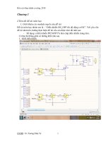
Thiết kế bộ giải mã 7 đoạn hiển thị chữ như hình trên. Các đầu vào c2, c1, c0 dùng để
thay đổi nội dung hiển thị.
b. Kết nối:
-
Input: SW2-0
-
Output: HEX0
c. Code Verilog
module part4(
input [2:0] SW,
output [6:0] HEX0);
//Connected
LED7 (SW[2:0], HEX0);
endmodule
//7-Segment Display=============================================
module LED7(
input [2:0] C,
output reg [6:0] Display);
always @ (*)
case(C)
3'b000:
3'b001:
3'b010:
3'b011:
3'b100:
default:
endcase
endmodule
5. Part 5
Display
Display
Display
Display
Display
Display
=
=
=
=
=
=
7'b0001001;
7'b0000110;
7'b1000111;
7'b1000111;
7'b1000000;
7'b1111111;
a. Yêu cầu:
7
//H
//E
//L
//L
//O
//Blank
-
Thiết kế mạch hiển thị chữ H E L L O như hình trên. Mạch bao gồm 5 bộ ghép kênh 5to-1 rộng ba bit và 5 bộ giải mã led 7 đoạn.
b. Kết nối:
-
Input: SW17-15, SW14-0
-
Output: HEX4, HEX3, HEX2, HEX1 và HEX0
c. Code Verilog
module part5(
input [17:0] SW,
output [6:0] HEX0, HEX1, HEX2, HEX3,
wire [2:0] M4, M3, M2, M1, M0;
wire [2:0] H, E, L1, L2, O;
assign H = SW[14:12];
assign E = SW[11:9];
assign L1 = SW[8:6];
assign L2 = SW[5:3];
assign O = SW[2:0];
//5 Multiplexer
mux_3 m4 (SW[17:15], H, E, L1, L2,
mux_3 m3 (SW[17:15], E, L1, L2, O,
mux_3 m2 (SW[17:15], L1, L2, O, H,
mux_3 m1 (SW[17:15], L2, O, H, E,
mux_3 m0 (SW[17:15], O, H, E, L1,
//Display H E L L O
LED7 l4 (M4, HEX4);
LED7 l3 (M3, HEX3);
LED7 l2 (M2, HEX2);
LED7 l1 (M1, HEX1);
LED7 l0 (M0, HEX0);
endmodule
8
HEX4);
O,
H,
E,
L1,
L2,
M4);
M3);
M2);
M1);
M0);
//Multiplexer 3 bit 5 to 1=======================================
module mux_3 (
input [2:0] S, U, V, W, X, Y,
output reg [2:0] M);
always @ (*)
case (S)
3'b000: M <= U;
3'b001: M <= V;
3'b010: M <= W;
3'b011: M <= X;
3'b1xx: M <= Y;
endcase
endmodule
//7-Segment Display=============================================
module LED7(
input [2:0] data,
output reg [6:0] led);
always @ (*)
case(data)
3'b000: led
3'b001: led
3'b010: led
3'b011: led
3'b100: led
default:led
endcase
endmodule
=
=
=
=
=
=
7'b0001001;
7'b0000110;
7'b1000111;
7'b1000111;
7'b1000000;
7'b1111111;
6. Part 6
a. Yêu cầu:
9
//H
//E
//L
//L
//O
//Blank
-
Thiết kế mạch hiển thị chữ H E L L O nhưng có thêm các khoảng trống như hình trên.
b. Kết nối:
-
Input: SW17-15, SW14-0
-
Output: HEX7, HEX6, HEX5, HEX4, HEX3, HEX2, HEX1, HEX0
c. Code Verilog:
module part6(
input [17:0] SW,
output [6:0] HEX0, HEX1, HEX2, HEX3, HEX4, HEX5, HEX6, HEX7);
wire [2:0] M7, M6, M5, M4, M3, M2, M1, M0;
wire [2:0] H, E, L1, L2, O, b1, b2, b3;
assign H = SW[14:12];
assign E = SW[11:9];
assign L1 = SW[8:6];
assign L2 = SW[5:3];
assign O = SW[2:0];
//Blank
assign b1 = 3'b111;
assign b2 = 3'b111;
assign b3 = 3'b111;
//Multiplexer
mux_3 m7 (SW[17:15], b3,
mux_3 m6 (SW[17:15], b2,
mux_3 m5 (SW[17:15], b1,
mux_3 m4 (SW[17:15], H,
mux_3 m3 (SW[17:15], E,
mux_3 m2 (SW[17:15], L1,
mux_3 m1 (SW[17:15], L2,
mux_3 m0 (SW[17:15], O,
//Display H E L L O
LED7 h7 (M7, HEX7);
LED7 h6 (M6, HEX6);
LED7 h5 (M5, HEX5);
LED7 h4 (M4, HEX4);
LED7 h3 (M3, HEX3);
LED7 h2 (M2, HEX2);
LED7 h1 (M1, HEX1);
LED7 h0 (M0, HEX0);
endmodule
b2,
b1,
H,
E,
L1,
L2,
O,
b3,
10
b1,
H,
E,
L1,
L2,
O,
b3,
b2,
H,
E,
L1,
L2,
O,
b3,
b2,
b1,
E,
L1,
L2,
O,
b3,
b2,
b1,
H,
L1,
L2,
O,
b3,
b2,
b1,
H,
E,
L2,
O,
b3,
b2,
b1,
H,
E,
L1,
O,
b3,
b2,
b1,
H,
E,
L1,
L2,
M7);
M6);
M5);
M4);
M3);
M2);
M1);
M0);
//Multiplexer 3-bit 5 to 1=======================================
module mux_3 (
input [2:0] S, U, V, W, X, Y, J, K, L,
output reg [2:0] M);
always @ (*)
case (S)
3'b000: M <= U;
3'b001: M <= V;
3'b010: M <= W;
3'b011: M <= X;
3'b100: M <= Y;
3'b101: M <= J;
3'b110: M <= K;
3'b111: M <= L;
endcase
endmodule
//7-Segment Display=============================================
module LED7(
input [2:0] data,
output reg [6:0] led);
always @ (*)
case(data)
3'b000: led
3'b001: led
3'b010: led
3'b011: led
3'b100: led
default:led
endcase
endmodule
=
=
=
=
=
=
7'b0001001;
7'b0000110;
7'b1000111;
7'b1000111;
7'b1000000;
7'b1111111;
11
//H
//E
//L
//L
//O
//Blank
LABORATORY EXERCISE 2
Numbers and Displays
1. Part 1
a. Yêu cầu:
-
Thiết kế mạch hiển thị các chữ số từ 0 đến 9 lên led 7 đoạn.
b. Kết nối:
-
Input: SW15-0
-
Output: HEX3, HEX2, HEX1, HEX0
c. Code Verilog:
module part1(
input [15:0]SW,
output [6:0]HEX0, HEX1, HEX2, HEX3);
//Connected
LED7 l0 (SW[15:12], HEX0);
LED7 l1 (SW[11:8], HEX1);
LED7 l2 (SW[7:4],
HEX2);
LED7 l3 (SW[3:0],
HEX3);
endmodule
//7-Segment Display Decimal=====================================
module LED7(
input [3:0] data,
output reg [6:0] led);
always @ (*)
case (data)
4'b0000: led <= 7'b1000000; //0
4'b0001: led <= 7'b1111001; //1
4'b0010: led <= 7'b0100100; //2
4'b0011: led <= 7'b0110000; //3
4'b0100: led <= 7'b0011001; //4
4'b0101: led <= 7'b0010010; //5
4'b0110: led <= 7'b0000010; //6
4'b0111: led <= 7'b1111000; //7
4'b1000: led <= 7'b0000000; //8
4'b1001: led <= 7'b0010000; //9
default: led <= 7'b1111111; //?
endcase
endmodule
12
2. Part 2
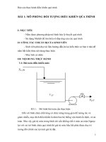
a. Yêu cầu:
-
Dựa vào hình trên thiết kế mạch tổ hợp hiển thị số 4-bit lên 2 led 7 đoạn để hiển thị hàng
chục và hàng đơn vị của số này.
b. Kết nối:
-
Input: SW3-0
-
Output: HEX1, HEX0
c. Code Verilog
module part2(
input [3:0]SW,
output [6:0]HEX0, HEX1);
wire
z;
wire [2:0]a;
wire [3:0]m;
13
//Tens
comparator
circuitB
//Units
circuitA
mux s3
mux s2
mux s1
mux s0
LED7
(SW[3:0], z);
(z,
HEX1);
(SW[2:0],
(z,
(z,
(z,
(z,
(m[3:0],
a);
SW[3],
SW[2],
SW[1],
SW[0],
HEX0);
1'b0,
a[2],
a[1],
a[0],
m[3]);
m[2]);
m[1]);
m[0]);
endmodule
//Circuit A=====================================================
module circuitA(
input [2:0]in,
output [2:0]out);
assign out[2] = in[2]&in[1];
assign out[1] = in[2]&(~in[1]);
assign out[0] = (in[1]&in[0])|(in[2]&in[0]);
endmodule
//Multiplexer 2 to 1============================================
module mux(
input S, X, Y,
output M);
assign M = (S==1'b1) ? X : Y;
endmodule
//Comparator====================================================
module comparator(
input [3:0]in,
output z);
assign z = (in[3]&in[2])|(in[3]&in[1]);
endmodule
//Circuit B/7-Segment Display TENS==============================
module circuitB(
input z,
output [6:0]led);
assign led = z?7'b1111001:
7'b1000000; //1 or 0
endmodule
14
//7-Segment Display UNITS=======================================
module LED7(
input [3:0] data,
output reg [6:0] led);
always @ (*)
case (data)
4'b0000:
4'b0001:
4'b0010:
4'b0011:
4'b0100:
4'b0101:
4'b0110:
4'b0111:
4'b1000:
4'b1001:
default:
endcase
endmodule
led
led
led
led
led
led
led
led
led
led
led
<=
<=
<=
<=
<=
<=
<=
<=
<=
<=
<=
7'b1000000;
7'b1111001;
7'b0100100;
7'b0110000;
7'b0011001;
7'b0010010;
7'b0000010;
7'b1111000;
7'b0000000;
7'b0010000;
7'b1111111;
//0
//1
//2
//3
//4
//5
//6
//7
//8
//9
//?
3. Part 3
a. Yêu cầu:
-
Thiết kế bộ cộng 2 số 4 bit từ bộ cộng toàn phần FA(Full Adder)
b. Kết nối:
-
Input: SW8, SW7-0
-
Output: LEDG4-0
c. Code Verilog:
15
module part3(
input [17:0]SW,
output [17:0]LEDR,
output [7:0]LEDG);
assign LEDR = SW;
//Connected
FA_4 (SW[7:4], SW[3:0], SW[8], LEDG[4], LEDG[3:0]);
endmodule
//Full Adder 4-bit==============================================
module FA_4(
input [3:0]A, B,
input Cin,
output Cout,
output [3:0]S);
//Net Cin & Cout
wire [3:1]c;
//Connected
FA f0 (A[0], B[0], Cin, c[1], S[0]);
FA f1 (A[1], B[1], c[1], c[2], S[1]);
FA f2 (A[2], B[2], c[2], c[3], S[2]);
FA f3 (A[3], B[3], c[3], Cout, S[3]);
endmodule
//Full Adder====================================================
module FA(
input A, B, Cin,
output Cout, S);
assign S = Cin^A^B;
assign Cout = (A^B)?Cin:B;
endmodule
4. Part 4
a. Yêu cầu:
-
Thiết kế mạch tổ hợp có chức năng cộng hai số BCD A + B = S2S1 sau đó hiển thị các
giá trị lên led 7 đoạn.
b. Kết nối:
-
Input: SW8, SW7-0
-
Output: LEDR8-0, HEX7, HEX5, HEX1, HEX0
16
c. Code Verilog
module part4(
input [8:0]SW,
output [8:0]LEDR,
output [6:0]HEX0, HEX1, HEX5, HEX7);
wire
wire
wire
wire
[3:0]data_S;
data_Cout;
[3:0]a, m;
z, bi;
assign bi = data_Cout|z;
assign LEDR = SW;
//Display A, B
LED7 A (SW[7:4], HEX7);
LED7 B (SW[3:0], HEX5);
//A + B = S
FA_4
(SW[7:4], SW[3:0], SW[8], data_Cout, data_S);
//Display S2
comparator (data_S, z);
circuitB
(bi, HEX1);
//Display S1
circuitA (data_S, a);
mux s3
(bi, data_S[3], a[3], m[3]);
mux s2
(bi, data_S[2], a[2], m[2]);
mux s1
(bi, data_S[1], a[1], m[1]);
mux s0
(bi, data_S[0], a[0], m[0]);
LED7 S
(m, HEX0);
endmodule
//Circuit A=====================================================
module circuitA(
input [3:0]in,
output [3:0]out);
assign out[3] = (~in[3]) & in[2] & in[1];
assign out[2] = ((~in[3]) & (~in[2]) & (~in[1]))|(in[3] &
in[2] & in[1]);
assign out[1] = ((~in[3]) & (~in[2]) & (~in[1]))|(in[3] &
in[2] & (~in[1]));
assign out[0] = ((~in[3]) & (~in[2]) & in[0])|(in[3] &
in[2] & in[0])|((~in[2] & in[1] & in[0]));
endmodule
17
//Multiplexer 2 to 1============================================
module mux(
input S, X, Y,
output M);
assign M = (S==1'b1) ? X : Y;
endmodule
//Comparator====================================================
module comparator(
input [3:0]in,
output z);
assign z = (in[3] & in[2])|(in[3] & in[1]);
endmodule
//Circuit B/7-Segment Display TENS==============================
module circuitB(
input z,
output [6:0]led);
assign led = z?7'b1111001:
7'b1000000; //1 or 0
endmodule
//7-Segment Display Decimal=====================================
module LED7(
input [3:0] data,
output reg [6:0] led);
always @ (*)
case (data)
4'b0000:
4'b0001:
4'b0010:
4'b0011:
4'b0100:
4'b0101:
4'b0110:
4'b0111:
4'b1000:
4'b1001:
default:
endcase
endmodule
led
led
led
led
led
led
led
led
led
led
led
<=
<=
<=
<=
<=
<=
<=
<=
<=
<=
<=
7'b1000000;
7'b1111001;
7'b0100100;
7'b0110000;
7'b0011001;
7'b0010010;
7'b0000010;
7'b1111000;
7'b0000000;
7'b0010000;
7'b1111111;
18
//0
//1
//2
//3
//4
//5
//6
//7
//8
//9
//?
//Full Adder 4-bit==============================================
module FA_4(
input [3:0]A, B,
input Cin,
output Cout,
output [3:0]S);
//Net Cin & Cout
wire [3:1]c;
//Connected
FA f0 (A[0], B[0], Cin, c[1], S[0]);
FA f1 (A[1], B[1], c[1], c[2], S[1]);
FA f2 (A[2], B[2], c[2], c[3], S[2]);
FA f3 (A[3], B[3], c[3], Cout, S[3]);
endmodule
//Full Adder====================================================
module FA(
input A, B, Cin,
output Cout, S);
assign S = Cin ^ A ^ B;
assign Cout = (A ^ B)?Cin:B;
endmodule
5. Part 5
a. Yêu cầu
-
Thiết kế mạch tổ hợp có chức năng cộng hai số BCD A1A0 + B1B0 = S2S1S0, hiển thị
các giá trị lên led 7 đoạn.
b. Kết nối:
-
Input: SW15-8, SW7-0
-
Output: HEX7, HEX6, HEX5, HEX4, HEX2, HEX1, HEX0
c. Code Verilog
module part5(
input [15:0]SW,
output [15:0]LEDR,
output [6:0]HEX0, HEX1, HEX2, HEX3, HEX4, HEX5, HEX6, HEX7);
wire Cout0, Sum2;
19
wire [3:0]Sum1, Sum0;
assign LEDR = SW;
//Display A
LED7 A1 (SW[15:12], HEX7);
LED7 A0 (SW[11:8], HEX6);
//Display B
LED7 B1 (SW[7:4],
HEX5);
LED7 B0 (SW[3:0],
HEX4);
//A1A0 + B1B0
BCD_adder A0B0 (SW[11:8], SW[3:0], 1'b0, Cout0, Sum0);
BCD_adder A1B1 (SW[15:12], SW[7:4], Cout0, Sum2, Sum1);
//Display S
circuitB (Sum2, HEX2);
LED7 S1 (Sum1, HEX1);
LED7 S0 (Sum0, HEX0);
endmodule
//BCD Adder=====================================================
module BCD_adder(
input [3:0] A, B,
input Cin,
output Cout,
output [3:0]S);
wire
wire
wire
wire
[3:0]data_S;
data_Cout;
[3:0]a, m;
z, bi;
assign bi = data_Cout|z;
assign Cout = bi;
assign S = m;
//Connected
FA_4
(A, B, Cin, data_Cout, data_S);
comparator (data_S, z);
circuitA
(data_S, a);
mux s3 (bi, data_S[3], a[3], m[3]);
mux s2 (bi, data_S[2], a[2], m[2]);
mux s1 (bi, data_S[1], a[1], m[1]);
mux s0 (bi, data_S[0], a[0], m[0]);
endmodule
//Circuit A=====================================================
module circuitA(
input [3:0]in,
output [3:0]out);
20
assign out[3] = (~in[3]) & in[2] & in[1];
assign out[2] = ((~in[3]) & (~in[2]) & (~in[1]))|(in[3] &
in[2] & in[1]);
assign out[1] = ((~in[3]) & (~in[2]) & (~in[1]))|(in[3] &
in[2] & (~in[1]));
assign out[0] = ((~in[3]) & (~in[2]) & in[0])|(in[3] &
in[2] & in[0])|((~in[2] & in[1] & in[0]));
endmodule
//Multiplexer 2 to 1============================================
module mux(
input S, X, Y,
output M);
assign M = (S==1'b1) ? X : Y;
endmodule
//Comparator====================================================
module comparator(
input [3:0]in,
output z);
assign z = (in[3] & in[2])|(in[3] & in[1]);
endmodule
//Circuit B/7-Segment Display TENS==============================
module circuitB(
input z,
output [6:0]led);
assign led = z?7'b1111001:7'b1000000; //1 or 0
endmodule
//7-Segment Display Decimal=====================================
module LED7(
input [3:0] data,
output reg [6:0] led);
always @ (*)
case (data)
4'b0000:
4'b0001:
4'b0010:
4'b0011:
4'b0100:
4'b0101:
4'b0110:
led
led
led
led
led
led
led
<=
<=
<=
<=
<=
<=
<=
7'b1000000;
7'b1111001;
7'b0100100;
7'b0110000;
7'b0011001;
7'b0010010;
7'b0000010;
21
//0
//1
//2
//3
//4
//5
//6
4'b0111: led <= 7'b1111000; //7
4'b1000: led <= 7'b0000000; //8
4'b1001: led <= 7'b0010000; //9
default: led <= 7'b1111111; //?
endcase
endmodule
//Full Adder 4-bit==============================================
module FA_4(
input [3:0]A, B,
input Cin,
output Cout,
output [3:0]S);
//Net Cin & Cout
wire [3:1]c;
//Connected
FA f0 (A[0], B[0], Cin, c[1], S[0]);
FA f1 (A[1], B[1], c[1], c[2], S[1]);
FA f2 (A[2], B[2], c[2], c[3], S[2]);
FA f3 (A[3], B[3], c[3], Cout, S[3]);
endmodule
//Full Adder====================================================
module FA(
input A, B, Cin,
output Cout, S);
assign S = Cin ^ A ^ B;
assign Cout = (A ^ B)?Cin:B;
endmodule
6. Part 6
a. Yêu cầu
-
Tương tự như Part 5 nhưng ta sử dụng lệnh if – else để thực hiện.
b. Kết nối:
-
Input: SW15-8, SW7-0
-
Output: HEX7, HEX6, HEX5, HEX4, HEX2, HEX1, HEX0
c. Code Verilog:
22
module part6(
input [15:0]SW,
output [6:0]HEX7, HEX6, HEX5, HEX4, HEX2, HEX1, HEX0);
wire [3:0] S2, S1, S0;
//Adder
adder (SW[15:12], SW[11:8], SW[7:4], SW[3:0], S2, S1, S0);
//Display B
LED7 B0 (SW[3:0], HEX4);
LED7 B1 (SW[7:4], HEX5);
//Display A
LED7 A0 (SW[11:8], HEX6);
LED7 A1 (SW[15:12],HEX7);
//Display S
LED7 S0 (S0,
HEX0);
LED7 S1 (S1,
HEX1);
LED7 S2 (S2,
HEX2);
endmodule
//Adder if else=================================================
module adder(
input [3:0]A1, A0, B1, B0,
output [3:0]S2, S1, S0);
wire [3:0]T1, T0;
reg [3:0]Z1, Z0;
reg [3:0]C2, C1, C0;
//Units
assign T0 = A0 + B0;
assign S0 = T0 - Z0;
always @ (*) begin
if (T0 > 4'd9) begin
Z0 = 4'd10;
C1 = 4'd1;
end
else begin
Z0 = 4'd0;
C1 = 4'd0;
end
end
//Tens
assign T1 = A1 + B1 + C1;
assign S1 = T1 - Z1;
always @ (*) begin
if (T1 > 4'd9) begin
23
Z1 = 4'd10;
C2 = 4'd1;
end
else begin
Z1 = 4'd0;
C2 = 4'd0;
end
end
//Hunds
assign S2 = C2;
endmodule
//7-Segment Display Decimal=====================================
module LED7(
input [3:0] data,
output reg [6:0] led);
always @ (*)
case (data)
4'b0000:
4'b0001:
4'b0010:
4'b0011:
4'b0100:
4'b0101:
4'b0110:
4'b0111:
4'b1000:
4'b1001:
default:
endcase
endmodule
led
led
led
led
led
led
led
led
led
led
led
<=
<=
<=
<=
<=
<=
<=
<=
<=
<=
<=
7'b1000000;
7'b1111001;
7'b0100100;
7'b0110000;
7'b0011001;
7'b0010010;
7'b0000010;
7'b1111000;
7'b0000000;
7'b0010000;
7'b1111111;
//0
//1
//2
//3
//4
//5
//6
//7
//8
//9
//?
7. Part 7
a. Yêu cầu:
-
Thiết kế mạch tổ hợp có chức năng giải mã 6 bit nhị phân thành số thập phân sau đó
hiển thị lên led 7 đoạn.
b. Kết nối:
-
Input: SW5-0
-
Output: HEX1, HEX0
24