Astm b 117 16
Bạn đang xem bản rút gọn của tài liệu. Xem và tải ngay bản đầy đủ của tài liệu tại đây (234.13 KB, 12 trang )
Designation: B117 − 16
Standard Practice for
Operating Salt Spray (Fog) Apparatus1
This standard is issued under the fixed designation B117; the number immediately following the designation indicates the year of
original adoption or, in the case of revision, the year of last revision. A number in parentheses indicates the year of last reapproval. A
superscript epsilon (´) indicates an editorial change since the last revision or reapproval.
This standard has been approved for use by agencies of the U.S. Department of Defense.
1. Scope
3. Significance and Use
1.1 This practice covers the apparatus, procedure, and
conditions required to create and maintain the salt spray (fog)
test environment. Suitable apparatus which may be used is
described in Appendix X1.
3.1 This practice provides a controlled corrosive environment which has been utilized to produce relative corrosion
resistance information for specimens of metals and coated
metals exposed in a given test chamber.
1.2 This practice does not prescribe the type of test specimen or exposure periods to be used for a specific product, nor
the interpretation to be given to the results.
3.2 Prediction of performance in natural environments has
seldom been correlated with salt spray results when used as
stand alone data.
3.2.1 Correlation and extrapolation of corrosion performance based on exposure to the test environment provided by
this practice are not always predictable.
3.2.2 Correlation and extrapolation should be considered
only in cases where appropriate corroborating long-term atmospheric exposures have been conducted.
1.3 The values stated in SI units are to be regarded as the
standard. The values given in parentheses are for information
only.
1.4 This standard does not purport to address all of the
safety concerns, if any, associated with its use. It is the
responsibility of the user of this standard to establish appropriate safety and health practices and determine the applicability of regulatory limitations prior to use.
3.3 The reproducibility of results in the salt spray exposure
is highly dependent on the type of specimens tested and the
evaluation criteria selected, as well as the control of the
operating variables. In any testing program, sufficient replicates should be included to establish the variability of the
results. Variability has been observed when similar specimens
are tested in different fog chambers even though the testing
conditions are nominally similar and within the ranges specified in this practice.
2. Referenced Documents
2.1 ASTM Standards:2
B368 Test Method for Copper-Accelerated Acetic Acid-Salt
Spray (Fog) Testing (CASS Test)
D609 Practice for Preparation of Cold-Rolled Steel Panels
for Testing Paint, Varnish, Conversion Coatings, and
Related Coating Products
D1193 Specification for Reagent Water
D1654 Test Method for Evaluation of Painted or Coated
Specimens Subjected to Corrosive Environments
E70 Test Method for pH of Aqueous Solutions With the
Glass Electrode
E691 Practice for Conducting an Interlaboratory Study to
Determine the Precision of a Test Method
G85 Practice for Modified Salt Spray (Fog) Testing
4. Apparatus
4.1 The apparatus required for salt spray (fog) exposure
consists of a fog chamber, a salt solution reservoir, a supply of
suitably conditioned compressed air, one or more atomizing
nozzles, specimen supports, provision for heating the chamber,
and necessary means of control. The size and detailed construction of the apparatus are optional, provided the conditions
obtained meet the requirements of this practice.
4.2 Drops of solution which accumulate on the ceiling or
cover of the chamber shall not be permitted to fall on the
specimens being exposed.
1
This practice is under the jurisdiction of ASTM Committee G01 on Corrosion
of Metals and is the direct responsibility of Subcommittee G01.05 on Laboratory
Corrosion Tests.
Current edition approved March 15, 2016. Published April 2016. Originally
approved in 1939. Last previous edition approved in 2011 as B117 – 11. DOI:
10.1520/B0117-16.
2
For referenced ASTM standards, visit the ASTM website, www.astm.org, or
contact ASTM Customer Service at For Annual Book of ASTM
Standards volume information, refer to the standard’s Document Summary page on
the ASTM website.
4.3 Drops of solution which fall from the specimens shall
not be returned to the solution reservoir for respraying.
4.4 Material of construction shall be such that it will not
affect the corrosiveness of the fog.
Copyright © ASTM International, 100 Barr Harbor Drive, PO Box C700, West Conshohocken, PA 19428-2959. United States
1
B117 − 16
and preferably parallel to the principal direction of flow of fog
through the chamber, based upon the dominant surface being
tested.
7.1.2 The specimens shall not contact each other or any
metallic material or any material capable of acting as a wick.
7.1.3 Each specimen shall be placed to permit unencumbered exposure to the fog.
7.1.4 Salt solution from one specimen shall not drip on any
other specimen.
4.5 All water used for this practice shall conform to Type IV
water in Specification D1193 (except that for this practice
limits for chlorides and sodium may be ignored). This does not
apply to running tap water. All other water will be referred to
as reagent grade.
NOTE 1—Water used with a conductivity ≤1.0 µS/cm (or resistivity ≥1.0
MΩ·cm) may cause damage to some equipment due to the reactive nature
of the water. In addition, it may cause issues with stabilizing pH
measurements.
NOTE 3—Suitable materials for the construction or coating of racks and
supports are glass, rubber, plastic, or suitably coated wood. Bare metal
shall not be used. Specimens shall preferably be supported from the
bottom or the side. Slotted wooden strips are suitable for the support of flat
panels. Suspension from glass hooks or waxed string may be used as long
as the specified position of the specimens is obtained, if necessary by
means of secondary support at the bottom of the specimens.
5. Test Specimens
5.1 The type and number of test specimens to be used, as
well as the criteria for the evaluation of the test results, shall be
defined in the specifications covering the material or product
being exposed or shall be mutually agreed upon between the
purchaser and the seller.
8. Salt Solution
6. Preparation of Test Specimens
8.1 The salt solution shall be prepared by dissolving 5 6 1
parts by mass of sodium chloride in 95 parts of water
conforming to Type IV water in Specification D1193 (except
that for this practice limits for chlorides and sodium may be
ignored). Careful attention should be given to the chemical
content of the salt. The salt used shall be sodium chloride with
not more than 0.3 % by mass of total impurities. Halides
(Bromide, Fluoride, and Iodide) other than Chloride shall
constitute less than 0.1 % by mass of the salt content. Copper
content shall be less than 0.3 ppm by mass. Sodium chloride
that has had anti-caking agents added shall not be used because
such agents may act as corrosion inhibitors. See Table 1 for a
listing of these impurity restrictions. Upon agreement between
the purchaser and the seller, analysis may be required and
limits established for elements or compounds not specified in
the chemical composition given above.
6.1 Specimens shall be suitably cleaned. The cleaning
method shall be optional depending on the nature of the surface
and the contaminants. Care shall be taken that specimens are
not recontaminated after cleaning by excessive or careless
handling.
6.2 Specimens for the evaluation of paints and other organic
coatings shall be prepared in accordance with applicable
specification(s) for the material(s) being exposed, or as agreed
upon between the purchaser and the supplier. Otherwise, the
test specimens shall consist of steel meeting the requirements
of Practice D609 and shall be cleaned and prepared for coating
in accordance with the applicable procedure of Practice D609.
6.3 Specimens coated with paints or nonmetallic coatings
shall not be cleaned or handled excessively prior to test.
6.4 Whenever it is desired to determine the development of
corrosion from an abraded area in the paint or organic coating,
a scratch or scribed line shall be made through the coating with
a sharp instrument so as to expose the underlying metal before
testing. The conditions of making the scratch shall be as
defined in Test Method D1654, unless otherwise agreed upon
between the purchaser and the seller.
8.2 The pH of the salt solution shall be such that when
atomized at 35°C (95°F) the collected solution will be in the
pH range from 6.5 to 7.2 (Note 4). Before the solution is
atomized it shall be free of suspended solids (Note 5). The pH
measurement shall be made at 23 6 3°C (73 6 5°F) using a
suitable glass pH-sensing electrode, reference electrode, and
pH meter system in accordance with Test Method E70. pH
measurement shall be recorded once daily (except on
weekends, or holidays when the salt spray test is not interrupted for exposing, rearranging, or removing test specimens
or to check and replenish the solution in the reservoir. The
maximum interval between pH measurements shall not exceed
96 h). Only diluted, reagent grade hydrochloric acid (HCl) or
reagent grade sodium hydroxide (NaOH) shall be used to
adjust the pH.
6.5 Unless otherwise specified, the cut edges of plated,
coated, or duplex materials and areas containing identification
marks or in contact with the racks or supports shall be
protected with a suitable coating stable under the conditions of
the practice.
NOTE 2—Should it be desirable to cut test specimens from parts or from
preplated, painted, or otherwise coated steel sheet, the cut edges shall be
protected by coating them with paint, wax, tape, or other effective media
so that the development of a galvanic effect between such edges and the
adjacent plated or otherwise coated metal surfaces, is prevented.
NOTE 4—Temperature affects the pH of a salt solution prepared from
water saturated with carbon dioxide at room temperature and pH adjustment may be made by the following three methods:
(1) When the pH of a salt solution is adjusted at room temperature, and
atomized at 35°C (95°F), the pH of the collected solution will be higher
than the original solution due to the loss of carbon dioxide at the higher
temperature. When the pH of the salt solution is adjusted at room
temperature, it is therefore necessary to adjust it below 6.5 so the collected
solution after atomizing at 35°C (95°F) will meet the pH limits of 6.5 to
7.2. Take about a 50-mL sample of the salt solution as prepared at room
temperature, boil gently for 30 s, cool, and determine the pH. When the
7. Position of Specimens During Exposure
7.1 The position of the specimens in the salt spray chamber
during the test shall be such that the following conditions are
met:
7.1.1 Unless otherwise specified, the specimens shall be
supported or suspended between 15 and 30° from the vertical
2
B117 − 16
TABLE 1 Maximum Allowable Limits for Impurity Levels in
Sodium ChlorideA,B,C
9. Air Supply
9.1 The compressed air supply to the Air Saturator Tower
shall be free of grease, oil, and dirt before use by passing
through well-maintained filters (Note 7). This air should be
maintained at a sufficient pressure at the base of the Air
Saturator Tower to meet the suggested pressures of Table 2 at
the top of the Air Saturator Tower.
NOTE 1—A measurable limit for anti-caking agents is not being defined
as a result of how salt is manufactured. During salt manufacturing, it is
common practice to create salt slurry from the raw salt mined. A
crystallization process then captures the pure salt from this slurry. Some
naturally occurring anti-caking agents can be formed in this process and
are not removed from the resultant product. Avoid salt products where
extra anti-caking agents are added. Additionally, when doing an elemental
analysis of salt, there can be trace elements present that are either a
stand-alone element or part of an anti-caking agent. It is not economically
feasible to know where such elements came from due to the long list of
possible anti-caking agents for which there would have to be testing.
Therefore, a salt product that meets the impurity, halide, and copper limits
with no anti-caking agents added will be acceptable. The salt supplier can
provide an analysis of the salt with a statement indicating that anti-caking
agents were not added to the product.
Impurity Description
Allowable Amount
Total Impurities
Halides (Bromide, Fluoride and Iodide) excluding Chloride
Copper
Anti-caking Agents
# 0.3 %
< 0.1 %
< 0.3 ppm
None Added
NOTE 7—The air supply may be freed from oil and dirt by passing it
through a suitable oil/water extractor (that is commercially available) to
stop any oil from reaching the Air Saturator Tower. Many oil/water
extractors have an expiration indicator, proper preventive maintenance
intervals should take these into account.
9.2 The compressed air supply to the atomizer nozzle or
nozzles shall be conditioned by introducing it into the bottom
of a tower filled with water. A common method of introducing
the air is through an air dispersion device (X1.4.1). The level
of the water must be maintained automatically to ensure
adequate humidification. It is common practice to maintain the
temperature in this tower between 46 and 49°C (114–121°F) to
offset the cooling effect of expansion to atmospheric pressure
during the atomization process. Table 2 shows the temperature,
at different pressures, that are commonly used to offset the
cooling effect of expansion to atmospheric pressure.
A
A common formula used to calculate the amount of salt required by mass to
achieve a 5 % salt solution of a known mass of water is:
0.053 3 Mass of Water 5 Mass of NaCl required
The mass of water is 1 g per 1 mL. To calculate the mass of salt required in
grams to mix 1 L of a 5 % salt solution, multiply 0.053 by 1000 g (35.27 oz, the
mass of 1 L of water). This formula yields a result of 53 g (1.87 oz) of NaCl required
for each litre of water to achieve a 5 % salt solution by mass.
The 0.053 multiplier for the sodium chloride used above is derived by the
following:
1000 g (mass of a full L of water) divided by 0.95
(water is only 95 % of the total mixture by mass) yields 1053 g
This 1053 g is the total mass of the mixture of one L of water with a 5% sodium
chloride concentration. 1053 g minus the original weight of the L of water, 1000 g,
yields 53 g for the weight of the sodium chloride. 53 g of total sodium chloride
divided by the original 1000 g of water yields a 0.053 multiplier for the sodium
chloride.
As an example: to mix the equivalent of 200 L (52.83 gal) of 5 % sodium chloride
solution, mix 10.6 kg (23.37 lb) of sodium chloride into 200 L (52.83 gal) of water.
200 L of water weighs 200 000 g. 200 000 g of water × 0.053 (sodium chloride
multiplier) = 10 600 g of sodium chloride, or 10.6 kg.
B
In order to ensure that the proper salt concentration was achieved when mixing
the solution, it is recommended that the solution be checked with either a salimeter
hydrometer or specific gravity hydrometer. When using a salimeter hydrometer, the
measurement should be between 4 and 6 % at 25°C (77°F).
C
If the purity of the salt used is >99.9%, then the limits for halides can be ignored.
This is due to the fact that the halides cannot be $0.1% with a salt purity of
>99.9%. If the salt used is of lower purity, then test for halides.
9.3 Careful attention should be given to the relationship of
tower temperature to pressure since this relationship can have
a direct impact to maintaining proper collection rates (Note 8).
It is preferable to saturate the air at temperatures well above the
chamber temperature as insurance of a wet fog as listed in
Table 2.
NOTE 8—If the tower is run outside of these suggested temperature and
pressure ranges to achieve proper collection rates as described in 10.2 of
this practice, other means of verifying the proper corrosion rate in the
chamber should be investigated, such as the use of control specimens
(panels of known performance in the test conducted). It is preferred that
control panels be provided that bracket the expected test specimen
performance. The controls allow for the normalization of test conditions
during repeated running of the test and will also allow comparisons of test
results from different repeats of the same test. (Refer to Appendix X3,
Evaluation of Corrosive Conditions, for mass loss procedures).
10. Conditions in the Salt Spray Chamber
10.1 Temperature—The exposure zone of the salt spray
chamber shall be maintained at 35 6 2°C (95 6 3°F). Each set
point and its tolerance represents an operational control point
for equilibrium conditions at a single location in the cabinet
which may not necessarily represent the uniformity of conditions throughout the cabinet. The temperature within the
exposure zone of the closed cabinet shall be recorded (Note 9)
at least once daily (except on Saturdays, Sundays, and holidays
when the salt spray test is not interrupted for exposing,
pH of the salt solution is adjusted to 6.5 to 7.2 by this procedure, the pH
of the atomized and collected solution at 35°C (95°F) will come within
this range.
(2) Heating the salt solution to boiling and cooling to 35°C (95°F) and
maintaining it at 35°C (95°F) for approximately 48 h before adjusting the
pH produces a solution the pH of which does not materially change when
atomized at 35°C (95°F).
(3) Heating the water from which the salt solution is prepared to 35°C
(95°F) or above, to expel carbon dioxide, and adjusting the pH of the salt
solution within the limits of 6.5 to 7.2 produces a solution the pH of which
does not materially change when atomized at 35°C (95°F).
NOTE 5—The freshly prepared salt solution may be filtered or decanted
before it is placed in the reservoir, or the end of the tube leading from the
solution to the atomizer may be covered with a double layer of cheesecloth
to prevent plugging of the nozzle.
NOTE 6—The pH can be adjusted by additions of dilute ACS reagent
grade hydrochloric acid or sodium hydroxide solutions.
TABLE 2 Suggested Temperature and Pressure Guideline
for the Top of the Air Saturator Tower for the Operation of a Test
at 35°C (95°F)
Air Pressure, kPa
83
96
110
124
3
Temperature, °C
46
47
48
49
Air Pressure, psi
12
14
16
18
Temperature, °F
114
117
119
121
B117 − 16
ture3 and can be used to determine if the sample measured is within
specification. The sample to be measured may be a composite sample from
multiple fog-collecting devices within a single cabinet, if necessary, to
obtain sufficient solution volume for measurement.
Table 3 shows the salt concentration and salt density of 4 %, 5 % and
6 % salt solution between 20°C and 40°C. A measurement that falls within
the range between 4 % and 6 % is acceptable.
It is important to understand the equipment being used to measure
specific gravity. One common practice for specific gravity measurement is
the use of a hydrometer. If used, careful attention to the hydrometer type
is important as most are manufactured and calibrated for measurements at
15.6°C (60°F). Since salt density is temperature dependent, an offset will
be necessary to make an accurate measurement at other temperatures.
Contact the hydrometer manufacturer to find the proper offset for the
hydrometer being used.
NOTE 12—Salt solutions from 2 to 6 % will give the same results,
though for uniformity the limits are set at 4 to 6 %.
rearranging, or removing test specimens or to check and
replenish the solution in the reservoir)
NOTE 9—A suitable method to record the temperature is by a continuous recording device or by a thermometer which can be read from outside
the closed cabinet. The recorded temperature must be obtained with the
salt spray chamber closed to avoid a false low reading because of wet-bulb
effect when the chamber is open.
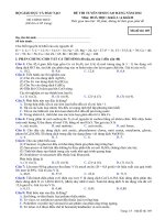
10.2 Atomization and Quantity of Fog—Place at least two
clean fog collectors per atomizer tower within the exposure
zone so that no drops of solution will be collected from the test
specimens or any other source. Position the collectors in the
proximity of the test specimens, one nearest to any nozzle and
the other farthest from all nozzles. A typical arrangement is
shown in Fig. 1. The fog shall be such that for each
80 cm2 (12.4 in.2) of horizontal collecting area, there will be
collected from 1.0 to 2.0 mL of solution per hour based on an
average run of at least 16 h (Note 10). The sodium chloride
concentration of the collected solution shall be 5 6 1 mass %
(Notes 10-12). The pH of the collected solution shall be 6.5 to
7.2. The pH measurement shall be made as described in 8.2
(Note 4). Both sodium chloride concentration (measured as
specific gravity) and volume of condensate collected (measured in mL) shall be recorded once daily (except on
weekends, or holidays when the salt spray test is not interrupted for exposing, rearranging, or removing test specimens
or to check and replenish the solution in the reservoir. The
maximum interval between these data collection measurements
shall not exceed 96 h).
10.3 The nozzle or nozzles shall be so directed or baffled
that none of the spray can impinge directly on the test
specimens.
11. Continuity of Exposure
11.1 Unless otherwise specified in the specifications covering the material or product being tested, the test shall be
continuous for the duration of the entire test period. Continuous operation implies that the chamber be closed and the spray
operating continuously except for the short daily interruptions
necessary to inspect, rearrange, or remove test specimens, to
check and replenish the solution in the reservoir, and to make
necessary recordings as described in Section 10.
NOTE 13—Operations should be so scheduled that the cumulative
NOTE 10—Suitable collecting devices are glass or plastic funnels with
the stems inserted through stoppers into graduated cylinders, or crystallizing dishes. Funnels and dishes with a diameter of 10 cm (3.94 in.) have
an area of about 80 cm2 (12.4 in.2).
NOTE 11—The specific gravity of salt solution will change with
temperature. Table 3 shows salt concentration and density versus tempera-
3
“Thermodynamic Properties of the NaCl + H2O system II. Thermodynamic
Properties of NaCl(aq), NaCl.2H2O(cr), and Phase Equilibria,” Journal of Physics
and Chemistry Reference Data, Vol. 21, No. 4, 1992.
NOTE 1—This figure shows a typical fog collector arrangement for a single atomizer tower cabinet. The same fog collector arrangement is also
applicable for multiple atomizer tower and horizontal (“T” type) atomizer tower cabinet constructions as well.
FIG. 1 Arrangement of Fog Collectors
4
B117 − 16
TABLE 3 Temperature versus Density Data
Density, g/cm3
Temperature
°C (°F)
4-percent Salt Concentration
5-percent Salt Concentration
6-percent Salt
Concentration
20 (68)
21 (69.8)
22 (71.6)
23 (73.4)
24 (75.2)
25 (77)
26 (78.8)
27 (80.6)
28 (82.4)
29 (84.2)
30 (86)
31 (87.8)
32 (89.6)
33 (91.4)
34 (93.2)
35 (95)
36 (96.8)
37 (98.6)
38 (100.4)
39 (102.2)
40 (104)
1.025758
1.025480
1.025193
1.024899
1.024596
1.024286
1.023969
1.023643
1.023311
1.022971
1.022624
1.022270
1.021910
1.021542
1.021168
1.020787
1.020399
1.020006
1.019605
1.019199
1.018786
1.032360
1.032067
1.031766
1.031458
1.031142
1.030819
1.030489
1.030152
1.029808
1.029457
1.029099
1.028735
1.028364
1.027986
1.027602
1.027212
1.026816
1.026413
1.026005
1.025590
1.025170
1.038867
1.038560
1.038245
1.037924
1.037596
1.037261
1.036919
1.036570
1.036215
1.035853
1.035485
1.035110
1.034729
1.034343
1.033950
1.033551
1.033146
1.032735
1.032319
1.031897
1.031469
15.1.3 Data obtained from each fog-collecting device of
volume of salt solution collected in millilitres per hour per
80 cm2 (12.4 in.2).
15.1.4 Concentration or specific gravity of collected solution and the temperature of that solution when measured.
Follow Table 3 for salt concentration and density versus
temperature to determine that the sample measured is within
specification. Sample to be measured may be a composite
sample from multiple fog-collecting devices (within a single
cabinet), if necessary to obtain sufficient solution volume for
measurement.
15.1.5 pH of collected solution at 23 6 3°C (73 6 5°F).
Sample to be measured may be a composite sample from
multiple fog-collecting devices (within a single cabinet), if
necessary to obtain sufficient solution volume for measurement.
maximum time for these interruptions are held to 60 min or less per day.
It is recommended to have only one interruption per day if possible. If
interruption time is longer that 60 min, it should be noted in the test report.
12. Period of Exposure
12.1 The period of exposure shall be as designated by the
specifications covering the material or product being tested or
as mutually agreed upon between the purchaser and the seller.
NOTE 14—Recommended exposure periods are to be as agreed upon
between the purchaser and the seller, but exposure periods of multiples of
24 h are suggested.
13. Cleaning of Tested Specimens
13.1 Unless otherwise specified in the specifications covering the material or product being tested, specimens shall be
treated as follows at the end of the test:
13.1.1 The specimens shall be carefully removed.
15.2 Type of specimen and its dimensions, or number or
description of part,
13.2 Specimens may be gently washed or dipped in clean
running water not warmer than 38°C (100°F) to remove salt
deposits from their surface, and then immediately dried.
15.3 Method of cleaning specimens before and after testing,
15.4 Method of supporting or suspending article in the salt
spray chamber,
14. Evaluation of Results
15.5 Description of protection used as required in 6.5,
14.1 A careful and immediate examination shall be made as
required by the specifications covering the material or product
being tested or by agreement between the purchaser and the
seller.
15.6 Exposure period,
15.7 Interruptions in exposure, cause, and length of time,
and
15.8 Results of all inspections.
15. Records and Reports
15.1 The following information shall be recorded, unless
otherwise prescribed in the specifications covering the material
or product being tested:
15.1.1 Type of salt and water used in preparing the salt
solution.
15.1.2 All readings of temperature within the exposure zone
of the chamber.
NOTE 15—If any of the atomized salt solution which has not contacted
the test specimens is returned to the reservoir, it is advisable to record the
concentration or specific gravity of this solution also.
16. Keywords
16.1 controlled corrosive environment; corrosive conditions; determining mass loss; salt spray (fog) exposure
5
B117 − 16
APPENDIXES
(Nonmandatory Information)
X1. CONSTRUCTION OF APPARATUS
X1.1 Cabinets
TABLE X1.1 Operating Characteristics of Typical Spray Nozzle
X1.1.1 Standard salt spray cabinets are available from
several suppliers, but certain pertinent accessories are required
before they will function according to this practice and provide
consistent control for duplication of results.
Siphon
Height,
cm
10
20
30
40
X1.1.2 The salt spray cabinet consists of the basic chamber,
an air-saturator tower, a salt solution reservoir, atomizing
nozzles, specimen supports, provisions for heating the
chamber, and suitable controls for maintaining the desired
temperature.
Siphon
Height,
in.
4
8
12
16
X1.1.3 Accessories such as a suitable adjustable baffle or
central fog tower, automatic level control for the salt reservoir,
and automatic level control for the air-saturator tower are
pertinent parts of the apparatus.
X1.1.4 The size and shape of the cabinet shall be such that
the atomization and quantity of collected solution is within the
limits of this practice.
34
19
19
19
19
5
19
19
19
19
Air Flow, dm3/min
Air Pressure, kPa
69
103
138
26.5
31.5
36
26.5
31.5
36
26.5
31.5
36
26.6
31.5
36
Air Flow,
L/min
Air Pressure, psi
10
15
26.5
31.5
26.5
31.5
26.5
31.5
26.6
31.5
20
36
36
36
36
Solution Consumption, cm3/h
Air Pressure, kPa
34
69
103
138
2100
3840
4584
5256
636
2760
3720
4320
0
1380
3000
3710
0
780
2124
2904
5
2100
636
0
0
Solution
Consumption, mL/h
Air Pressure, psi
10
15
3840
4584
2760
3720
1380
3000
780
2124
20
5256
4320
3710
2904
X1.3.2 It can readily be seen that air consumption is
relatively stable at the pressures normally used, but a marked
reduction in solution sprayed occurs if the level of the solution
is allowed to drop appreciably during the test. Thus, the level
of the solution in the salt reservoir must be maintained
automatically to ensure uniform fog delivery during the test.4
X1.1.5 The chamber shall be made of suitably inert materials such as plastic, glass, or stone, or constructed of metal and
lined with impervious plastics, rubber, or epoxy-type materials
or equivalent.
X1.3.3 If the nozzle selected does not atomize the salt
solution into uniform droplets, it will be necessary to direct the
spray at a baffle or wall to pick up the larger drops and prevent
them from impinging on the test specimens. Pending a complete understanding of air-pressure effects, and so forth, it is
important that the nozzle selected shall produce the desired
condition when operated at the air pressure selected. Nozzles
are not necessarily located at one end, but may be placed in the
center and can also be directed vertically up through a suitable
tower.
X1.1.6 All piping that contacts the salt solution or spray
should be of inert materials such as plastic. Vent piping should
be of sufficient size so that a minimum of back pressure exists
and should be installed so that no solution is trapped. The
exposed end of the vent pipe should be shielded from extreme
air currents that may cause fluctuation of pressure or vacuum in
the cabinet.
X1.2 Temperature Control
X1.2.1 The maintenance of temperature within the salt
chamber can be accomplished by several methods. It is
generally desirable to control the temperature of the surroundings of the salt spray chamber and to maintain it as stable as
possible. This may be accomplished by placing the apparatus
in a constant-temperature room, but may also be achieved by
surrounding the basic chamber of a jacket containing water or
air at a controlled temperature.
X1.4 Air for Atomization
X1.4.1 The air used for atomization must be free of grease,
oil, and dirt before use by passing through well-maintained
filters. Room air may be compressed, heated, humidified, and
washed in a water-sealed rotary pump if the temperature of the
water is suitably controlled. Otherwise cleaned air may be
introduced into the bottom of a tower filled with water through
a porous stone or multiple nozzles. The level of the water must
be maintained automatically to ensure adequate humidification.
A chamber operated in accordance with this method and
Appendix X1 will have a relative humidity between 95 and
98 %. Since salt solutions from 2 to 6 % will give the same
results (though for uniformity the limits are set at 4 to 6 %), it
is preferable to saturate the air at temperatures well above the
X1.2.2 The use of immersion heaters in an internal salt
solution reservoir or within the chamber is detrimental where
heat losses are appreciable because of solution evaporation and
radiant heat on the specimens.
X1.3 Spray Nozzles
X1.3.1 Satisfactory nozzles may be made of hard rubber,
plastic, or other inert materials. The most commonly used type
is made of plastic. Nozzles calibrated for air consumption and
solution-atomized are available. The operating characteristics
of a typical nozzle are given in Table X1.1.
4
A suitable device for maintaining the level of liquid in either the saturator tower
or reservoir of test solution may be designed by a local engineering group, or it may
be purchased from manufacturers of test cabinets as an accessory.
6
B117 − 16
air temperature sufficiently to offset heat losses, except those
that can be replaced otherwise at very low-temperature gradients.
chamber temperature as insurance of a wet fog. Table X1.2
shows the temperatures, at different pressures, that are required
to offset the cooling effect of expansion to atmospheric
pressure.
X1.5 Types of Construction
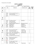
X1.5.1 A modern laboratory cabinet is shown in Fig. X1.1.
Walk-in chambers are usually constructed with a sloping
ceiling. Suitably located and directed spray nozzles avoid
ceiling accumulation and drip. Nozzles may be located at the
ceiling, or 0.91 m (3 ft) from the floor directed upward at 30 to
60° over a passageway. The number of nozzles depends on type
and capacity and is related to the area of the test space. An 11
to 19 L (3 to 5-gal) reservoir is required within the chamber,
with the level controlled. The major features of a walk-in type
cabinet, which differs significantly from the laboratory type,
are illustrated in Fig. X1.2. Construction of a plastic nozzle,
such as is furnished by several suppliers, is shown in Fig. X1.3.
X1.4.2 Experience has shown that most uniform spray
chamber atmospheres are obtained by increasing the atomizing
TABLE X1.2 Temperature and Pressure Requirements for
Operation of Test at 95°F
Temperature, °C
83
46
Temperature, °F
12
114
Air Pressure, kPa
96
110
47
48
Air Pressure, psi
14
16
117
119
124
49
18
121
7
B117 − 16
NOTE 1—This figure shows the various components including alternate arrangements of the spray nozzles and solution reservoir.
θ—Angle of lid, 90 to 125°
1—Thermometer and thermostat for controlling heater (Item No. 8) in base
2—Automatic water leveling device
3—Humidifying tower
4—Automatic temperature regulator for controlling heater (Item No. 5)
5—Immersion heater, nonrusting
6—Air inlet, multiple openings
7—Air tube to spray nozzle
8—Heater in base
9—Hinged top, hydraulically operated, or counterbalanced
10—Brackets for rods supporting specimens, or test table
11—Internal reservoir
12—Spray nozzle above reservoir, suitably designed, located, and baffled
12A—Spray nozzle housed in dispersion tower located preferably in center of cabinet (typical examples)
13—Water seal
14—Combination drain and exhaust. Exhaust at opposite side of test space from spray nozzle (Item 12), but preferably in combination with drain, waste trap,
and forced draft waste pipe (Items 16, 17, and 19)
15—number not used
16—Complete separation between forced draft waste pipe (Item 17) and combination drain and exhaust (Items 14 and 19) to avoid undesirable suction
or back pressure
17—Forced draft waste pipe
18—Automatic leveling device for reservoir
19—Waste trap
20—Air space or water jacket
21—Test table or rack, well below roof area
FIG. X1.1 Typical Salt Spray Cabinet
8
B117 − 16
NOTE 1—The controls are the same, in general as for the smaller laboratory type cabinet (Fig. X1.1), but are sized to care for the larger cube. The
chamber has the following features:
θ—Angle of ceiling, 90 to 125°
1—Heavy insulated outer panels
2—Air space
3—Low-watt density heaters, or steam coils
4—Single- or double-, full-opening door (refrigeration type), with inward sloping door sill
5—Viewing window/s
6—Inner chamber vent
7—Inner chamber drain
8—Duct boards on floor
FIG. X1.2 Walk-in Chamber, 1.5 by 2.4 m (5 by 8 ft) and Upward in Overall Size
FIG. X1.3 Typical Spray Nozzle
X2. USE OF THE SALT SPRAY (FOG) TEST IN RESEARCH
number of specimens required to constitute an adequate sample
for test purposes. In this connection it is well to point out that
Practice B117 is not applicable to the study or testing of
decorative chromium plate (nickel-chromium) on steel or on
zinc-base die castings or of cadmium plate on steel. For this
purpose Test Method B368 and Practice G85 are available,
which are also considered by some to be superior for comparison of chemically treated aluminum (chromated, phosphated,
or anodized), although final conclusions regarding the validity
of test results related to service experience have not been
reached. Practice B117 and Practice G85 are considered to be
most useful in estimating the relative behavior of closely
related materials in marine atmospheres, since it simulates the
basic conditions with some acceleration due to either wetness
or temperature, or both.
X2.1 This practice is primarily used for process qualification and quality acceptance. Regarding any new applications, it
is essential to correlate the results of this practice with actual
field exposure results. (See Fig. X2.1.)
X2.2 The salt spray has been used to a considerable extent
for the purpose of comparing different materials or finishes. It
should be noted there is usually not a direct relation between
salt spray (fog) resistance and resistance to corrosion in other
media, because the chemistry of the reactions, including the
formation of films and their protective value, frequently varies
greatly with the precise conditions encountered. Informed
personnel are aware of the erratic composition of basic alloys,
the possibility of wide variations in quality and thickness of
plated items produced on the same racks at the same time, and
the consequent need for a mathematical determination of the
9
B117 − 16
NOTE 1—Dashed chart lines indicate temperature tolerance limits.
NOTE 2—Reprinted with permission.
(1) Salt Solution—5 ± 1 parts by mass of sodium chloride (NaCl) in 95 parts by mass of Specification D1193 Type IV water.
(2) pH 6.5 to 7.2 of collected solution.
(3) The exposure zone of the salt spray chamber shall be maintained at 35 ± 2°C (95 ± 3°F). Each set point and its tolerance represents an operational control
point for equilibrium conditions at a single location in the cabinet which may not necessarily represent the uniformity of conditions throughout the cabinet.
(4) Fog at a rate of 1.0 to 2.0 mL/h per 80 cm2 of horizontal collection area.
FIG. X2.1 Standard Practice for Operating Salt Spray (Fog) Apparatus
X3. EVALUATION OF CORROSIVE CONDITIONS
X3.1 General—This appendix covers test panels and procedures for evaluating the corrosive conditions within a salt
spray cabinet. The procedure involves the exposure of steel test
panels and the determination of their mass losses in a specified
period of time. This may be done monthly or more frequently
to ensure consistent operation over time. It is also useful for
correlating the corrosive conditions among different cabinets.
X3.4 Positioning of Test Panels—Place a minimum of two
weighed panels in the cabinet, with the 127-mm (5.0 in.) length
supported 30° from vertical. Place the panels in the proximity
of the condensate collectors. (See Section 6.)
X3.5 Duration of Test—Expose panels to the salt fog for 48
to 168 h.
X3.6 Cleaning of Test Panels After Exposure—After removal of the panels from the cabinet, rinse each panel
immediately with running tap water to remove salt, and rinse in
reagent grade water (see Specification D1193, Type IV).
Chemically clean each panel for 10 min at 20 to 25°C in a fresh
solution prepared as follows:
X3.2 Test Panels—The required test panels, 76 by 127 by
0.8 mm (3.0 by 5.0 by .0315 in.), are made from SAE 1008
commercial-grade cold-rolled carbon steel (UNS G10080).
X3.3 Preparation of Panels Before Testing—Clean panels
before testing by degreasing only, so that the surfaces are free
of dirt, oil, or other foreign matter that could influence the test
results. After cleaning, weigh each panel on an analytical
balance to the nearest 1.0 mg and record the mass.
Mix 1000 mL of hydrochloric acid (sp gr 1.19) with 1000 mL
reagent grade water (D1193, Type IV) and add 10 g of hexamethylene tetramine. After cleaning, rinse each panel with reagent
grade water (Type IV) and dry (see 13.2).
10
B117 − 16
TABLE X3.1 Repeatability Statistics
X3.7 Determining Mass Loss—Immediately after drying,
determine the mass loss by reweighing and subtracting panel
mass after exposure from its original mass.
NOTE 1—Based on two replicates in every test run. No. = number of
different salt spray cabinets in test program; r = 95 % repeatability limits,
g; Cv = Sr/avg, coefficient of variation, %; and Sr = repeatability standard
deviations, g.
X3.7.1 Data generated in the interlaboratory study using
this method are available from ASTM as a Research Report.5
X3.8 Precision and Bias—Steel Panel Test
X3.8.1 An interlaboratory test program using three different
sets of UNS G10080 steel panels, 76 by 127 by 0.8 mm (3.0 by
5.0 by .0315 in.) has shown that the repeatability of the mass
loss of the steel panels, that is, the consistency in mass loss
results that may be expected when replicate panels are run
simultaneously in a salt spray cabinet, is dependent upon
exposure time and the panel lot or source. The interlaboratory
program yielded repeatability standard deviations, Sr, from
which 95 % repeatability limits, r, were calculated as follows
(see Practice E691):
r 5 2.8 S r
Materials
Test
Duration, h
Average
Mass
Loss, g
Sr, g
Cv, %
r, g
No.
QP1
QP1
QP1
AP
AP
AP
QP2
QP2
QP2
48
96
168
48
96
168
48
96
168
0.8170
1.5347
2.5996
0.7787
1.4094
2.4309
0.8566
1.5720
2.7600
0.0588
0.1048
0.2498
0.0403
0.0923
0.1594
0.0686
0.0976
0.2588
7.20
7.28
9.61
5.17
6.55
6.56
8.01
6.21
9.38
0.1646
0.2934
0.6994
0.1128
0.2584
0.4463
0.1921
0.2733
0.7246
12
12
12
10
10
10
5
5
5
ibility standard deviations, SR, from which 95 % reproducibility limits, R, were calculated as follows (See Practice E691):
(X3.1)
R 5 2.8 S
X3.8.1.1 The values of Sr and r are reported in Table X3.1.
Note that the corrosion rate of steel in this environment is
approximately constant over the exposure interval and that the
ratio of the standard deviation to the average mass loss, the
coefficient of variation, Cv, varies between 5 and 10 % with a
weighted average of 7.4 % and an r of 621 % of the average
mass loss.
R
(X3.2)
X3.8.2.1 The values of SR and R are reported in Table X3.2.
Note that the ratio of standard deviation to the average mass
loss, the coefficient of variation, Cv, varies between 8 to 18 %
with a weighted average of 12.7 % and an R of 636 % of the
average mass loss.
X3.8.3 The mass loss of steel in this salt spray practice is
dependent upon the area of steel exposed, the temperature, time
of exposure, salt solution make up and purity, pH, spray
conditions, and the metallurgy of the steel. The procedure in
Appendix X3 for measuring the corrosivity of neutral salt spray
cabinets with steel panels has no bias because the value of
corrosivity of the salt spray is defined only in terms of this
practice.
X3.8.2 This interlaboratory program also produced results
on the reproducibility of results, that is, the consistency of mass
loss results in tests in different laboratories or in different
cabinets in the same facility. This program yielded reproduc5
Supporting data have been filed at ASTM International Headquarters and may
be obtained by requesting Research Report RR:G01-1003.
11
B117 − 16
TABLE X3.2 Reproducibility Statistics
NOTE 1—No. = number of different salt spray cabinets in test program;
R = 95 % reproduciblity limits, g; Cv = SR/avg, coefficient of variation,
%; and SR = reproducibility standard deviation, g.
Materials
Test
Duration, h
Average
Mass
Loss, g
SR, g
Cv, %
R, g
No.
QP1
QP1
QP1
AP
AP
AP
QP2
QP2
QP2
48
96
168
48
96
168
48
96
168
0.8170
1.5347
2.5996
0.7787
1.4094
2.4309
0.8566
1.5720
2.7600
0.0947
0.2019
0.3255
0.0805
0.1626
0.3402
0.1529
0.1319
0.3873
11.58
14.02
12.52
10.33
11.54
14.00
17.85
8.39
14.03
0.2652
0.5653
0.9114
0.2254
0.4553
0.9526
0.4281
0.3693
1.0844
12
12
12
10
10
10
5
5
5
ASTM International takes no position respecting the validity of any patent rights asserted in connection with any item mentioned
in this standard. Users of this standard are expressly advised that determination of the validity of any such patent rights, and the risk
of infringement of such rights, are entirely their own responsibility.
This standard is subject to revision at any time by the responsible technical committee and must be reviewed every five years and
if not revised, either reapproved or withdrawn. Your comments are invited either for revision of this standard or for additional standards
and should be addressed to ASTM International Headquarters. Your comments will receive careful consideration at a meeting of the
responsible technical committee, which you may attend. If you feel that your comments have not received a fair hearing you should
make your views known to the ASTM Committee on Standards, at the address shown below.
This standard is copyrighted by ASTM International, 100 Barr Harbor Drive, PO Box C700, West Conshohocken, PA 19428-2959,
United States. Individual reprints (single or multiple copies) of this standard may be obtained by contacting ASTM at the above
address or at 610-832-9585 (phone), 610-832-9555 (fax), or (e-mail); or through the ASTM website
(www.astm.org). Permission rights to photocopy the standard may also be secured from the Copyright Clearance Center, 222
Rosewood Drive, Danvers, MA 01923, Tel: (978) 646-2600; />
12