Astm c 336 71 (2015)
Bạn đang xem bản rút gọn của tài liệu. Xem và tải ngay bản đầy đủ của tài liệu tại đây (240.63 KB, 5 trang )
Designation: C336 − 71 (Reapproved 2015)
Standard Test Method for
Annealing Point and Strain Point of Glass by Fiber
Elongation1
This standard is issued under the fixed designation C336; the number immediately following the designation indicates the year of
original adoption or, in the case of revision, the year of last revision. A number in parentheses indicates the year of last reapproval. A
superscript epsilon (´) indicates an editorial change since the last revision or reapproval.
This standard has been approved for use by agencies of the U.S. Department of Defense.
1. Scope
3. Definitions
1.1 This test method covers the determination of the annealing point and the strain point of a glass by measuring the
viscous elongation rate of a fiber of the glass under prescribed
condition.
3.1 annealing point—that temperature at which internal
stresses in a glass are substantially relieved in a matter of
minutes.4,5,6 During a test in accordance with the requirements
of this method, the viscous elongation rate is measured by a
suitable extensometer while the specimen fiber is cooling at a
rate of 4 6 1°C/min. The elongation rate at the annealing point
is approximately 0.14 mm/min for a fiber of 0.65 mm diameter.6
1.2 The annealing and strain points shall be obtained by
following the specified procedure after calibration of the
apparatus using fibers of standard glasses having known
annealing and strain points, such as those specified and
certified by the National Institute of Standards and Technology
(NIST)2 (see Appendix X1).
3.2 annealing range—the range of glass temperature in
which stresses in glass articles can be relieved at a commercially desirable rate. For purposes of comparing glasses, the
annealing range is assumed to correspond with the temperatures between the annealing point (AP) and the strain point
(StP).
1.3 This standard does not purport to address all of the
safety concerns, if any, associated with its use. It is the
responsibility of the user of this standard to establish appropriate safety and health practices and determine the applicability of regulatory limitations prior to use.
3.3 strain point—that temperature at which the internal
stresses in a glass are substantially relieved in a matter of
hours. The strain point is determined by extrapolation of the
annealing point data and is the temperature at which the
viscous elongation rate is 0.0316 times that observed at the
annealing point.
2. Referenced Documents
2.1 ASTM Standards:3
C338 Test Method for Softening Point of Glass
C598 Test Method for Annealing Point and Strain Point of
Glass by Beam Bending
4. Significance and Use
4.1 This test method provides data useful for (1) estimating
stress release, (2) the development of proper annealing
schedules, and (3) estimating setting points for seals.
1
This test method is under the jurisdiction of ASTM Committee C14 on Glass
and Glass Products and is the direct responsibility of Subcommittee C14.04 on
Physical and Mechanical Properties.
Current edition approved Published May 2015. Originally approved in 1954.
Last previous edition approved in 2010 as C336 – 71 (2010). DOI: 10.1520/C033671R15.
2
Available from National Institute of Standards and Technology (NIST), 100
Bureau Dr., Stop 1070, Gaithersburg, MD 20899-1070, . Publication 260.
3
For referenced ASTM standards, visit the ASTM website, www.astm.org, or
contact ASTM Customer Service at For Annual Book of ASTM
Standards volume information, refer to the standard’s Document Summary page on
the ASTM website.
4
Littleton, J. T., and Roberts, E. H., “A Method for Determining the Annealing
Temperature of Glass,” Journal of the Optical Society of America, Vol 4, 1920, p.
224.
5
Lillie, H. R., “Viscosity of Glass Between the Strain Point and Melting
Temperature,” Journal of American Ceramic Society, Vol 14, 1931, p. 502;
“Re-Evaluation of Glass Viscosities at Annealing and Strain Points,” Journal of
American Ceramic Society, Vol 37, 1954, p. 111.
6
McGraw, D. A. and Babcock, C. L., “Effect of Viscosity and Stress Level on
Rate of Stress Release in Soda-Lime, Potash-Barium and Borosilicate Glasses,”
Journal of the American Ceramic Society, Vol 42, 1959, p. 330.
Copyright © ASTM International, 100 Barr Harbor Drive, PO Box C700, West Conshohocken, PA 19428-2959. United States
1
C336 − 71 (2015)
contact the copper; this can be ensured by placing a 6 mm
(1⁄4-in.) length of ceramic tube in the bottom of the hole ahead
of the couple. The cold junction of the thermocouple shall be
maintained in an ice bath during tests.
5.2.1 The temperature-indicating instrument, preferably a
potentiometer, shall be of such quality and sensitivity as to
permit reading the thermocouple emf to an amount corresponding to 0.1°C (0.2°F), equivalent to about 1 µV for a platinum
couple or to about 4 µV for a base-metal couple.
5.2.2 Provision shall be made for reading temperatures
accurately at predetermined moments. One means of accomplishing this is to maintain the potentiometer setting at an
electromotive force corresponding to a known temperature,
near the annealing point and inferring the temperature from the
deflection of a sensitive galvanometer, previously calibrated
for the purpose. It is convenient to adjust the galvanometer
shunt to a sensitivity of about 3°C (5.5°F)/cm of deflection and
to somewhat less than critical damping. This technique for
reading temperature changes is one of the preferred methods;
in the following sections it will be assumed that this technique
Accordingly, its usage is widespread throughout
manufacturing, research, and development. It can be utilized
for specification acceptance.
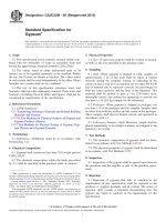
5. Apparatus
5.1 Furnace—The furnace shall be 368 mm (141⁄2-in.) long
and approximately 114 mm (41⁄2 in.) in diameter and shall
contain a copper core 305 mm (12 in.) long and 29 mm
(11⁄8 in.) in outside diameter, with inside diameter of 5.6 mm
(7⁄32 in.). It shall be constructed substantially as shown in Fig.
1.
5.1.1 Such a furnace will cool naturally at approximately
4°C (7°F)/min at 500°C (932°F) and at a rate exceeding 3°C
(5.5°F)/min at 400°C (752°F).
5.2 Temperature Measuring and Indicating Instruments—
For the measurement of temperature there shall be provided a
thermocouple, preferably platinum-platinum rhodium, inserted
in the upper side hole of the copper core, as indicated in Fig.
1, so that its junction is located midway in the length of the
core. The thermocouple wire shall not be allowed to directly
FIG. 1 Apparatus for Determination of Annealing Point and Strain Point of Glass
2
C336 − 71 (2015)
remaining fiber length or up to a maximum of 305 mm (12 in.).
Record the average diameter for subsequent calculations.
has been used, although any other equally sensitive and precise
method of following the temperature of the thermocouple may
be used.
7. Calibration with Standard Glass
5.3 Furnace Control—Suitable means shall be provided for
idling the furnace, controlling its heating rate, and, in the case
of very hard glasses, limiting the cooling rate to not more than
5°C (9°F)/min. A variable transformer is a convenient device
for this purpose. The transformer can also be employed as a
switch for interrupting the furnace current.
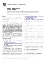
7.1 Calibration—Prepare at least four fibers of the calibrating or standard glass,2 with diameters covering the diameter
range 0.55 to 0.75 mm. In accordance with procedures in
Sections 8 and 9.1, determine the elongation rates at the
specified annealing point temperature, and make a calibration
plot as in Fig. 2, of the rate of elongation versus the reciprocal
square of the fiber diameter. Then use this calibration plot to
determine the annealing points of unknown glasses with
similar annealing ranges. It is recommended that the apparatus
be calibrated periodically depending upon usage.
5.4 Device for Measuring Elongation—The means of observing the rate of elongation of the fiber should be such as to
indicate reliably over a range of about 6 mm (1⁄4-in.) change in
fiber length with an uncertainty not greater than about 0.01 mm
(0.0004 in.). A convenient method is shown in Fig. 1, where the
arm of the optical lever, N, bears upon a platform, L, incorporated in the loading linkage. The fulcrum of the lever should be
mounted on a rigid (but height-adjustable) member, substantially free of vibration. With an optical lever arm about 38 mm
(11⁄2 in.) long and a scale distance of about 1 m (40 in.), the
multiplying factor is about 50. Readings can be made to 0.5
mm on the scale and, if the scale is 508 mm in length, a
sufficient range is attained. The scale is curved with its center
of curvature at the mirror location. The system may be
calibrated by mounting a micrometer screw in place of the
platform, L.
5.4.1 Any other extensometer arrangement, such as a linearly variable differential transformer (LVDT) or a travelling
microscope, is suitable for measuring elongation, provided that
length changes are reliably measured as specified.
8. Procedure
8.1 Method A:
8.1.1 Long Fiber, Furnace Support—The recommended
method of fiber support and loading is as shown in Fig. 1, in
which the top of a long fiber is supported on the furnace top
itself and the fiber extends entirely through the furnace to the
lever platform, L, or to the attachment of the load.
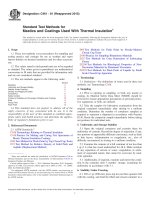
8.1.2 Long Fiber, Independent Support—An alternative long
fiber method is that shown in Fig. 3, in which the top of the
fiber is supported independently of the furnace. This method
requires the application of a correction for thermal expansion.5
8.2 Method B:
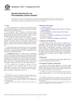
8.2.1 Short Fiber, Independent Support—The short fiber
method of support and loading is as shown in Fig. 4, in which
the short fiber is supported independently of the furnace
between two metal rods. This method requires a larger furnace
bore than Method A and application of a correction for thermal
expansion.5
8.2.2 Short Fiber, Furnace Support—In this method the
short fiber is joined to the two metal rods as in 7.2.1, except
that the upper metal rod is supported by the furnace, being
seated in the stainless steel support disk, J, in Fig. 1.
5.5 Micrometer Calipers, with a least count of 0.005 mm,
for measuring specimen fiber diameters.
6. Test Specimen
6.1 Drawing the Fiber—Draw a suitable fiber from 2 cm3
(more or less) of glass in any form such as a fragment, cane,
flat strip, or tubing. Stick the piece to handles of glass or other
suitable material, such as refractory or metal, and then work it
into a ball, using a flame adjustment found suitable for the
particular kind of glass. When the ball is in a uniform state of
proper temperature, and while it is still in the fire, slightly
elongate it into a pear shape. Then, remove the ball from the
fire, and draw it down to a convenient length.
8.3 Assembly of Specimen in Apparatus—With the furnace
at least 25°C (45°F) below the estimated annealing point, insert
the bottom end of the sample in the top of the furnace (Note).
6.2 Measurement of Fiber Dimensions—Measure the fiber
with micrometer calipers at 51 mm (2-in.) intervals, and select
a 508 mm (20-in.) length that is substantially circular in cross
section, has a diameter of 0.65 6 0.10 mm (0.025 6 0.004 in.),
and is uniform to 0.015 mm (60.0006 in.). The fiber used in
Method B of this test procedure may be between 102 mm
(4 in.) and 203 mm (8 in.) in length; once established, such a
short fiber specimen length must be maintained within6 2 mm
for all further calibration and testing.
6.3 Fiber Preparation—Prepare the selected length of fiber
for the test by melting both its ends down into spherical form
about 2.5 mm (0.1 in.) in diameter, taking care that the balls are
centered on the fiber axis. Starting 25.4 mm (1 in.) from one
end, which is thereafter to be regarded as the top end,
remeasure the fiber for diameter at 1 in. intervals over the
FIG. 2 Calibration
3
C336 − 71 (2015)
straight line to represent the plotted points as in Fig. 5, giving
more weight to the higher temperature data points.
9.2 Annealing Point—Select from the calibration plot in
Fig. 2 the elongation rate of the calibrating glass having the
same diameter as the test glass. Using the elongation rate thus
obtained, select corresponding potentiometer reading from the
plot of the glass under measurement. This potentiometer
reading indicates the annealing point temperature of the glass
under test.
FIG. 3 Apparatus Assembly for Independent Support of Sample
Fiber
9.3 Strain Point—Obtain the strain point by extrapolation of
the straight-line plot of Fig. 5. Divide the elongation rate at the
annealing point by 31.6 to obtain the elongation rate at the
strain point. From the plot in Fig. 5, select the potentiometer
reading corresponding to this elongation rate. This potentiometer reading indicates the strain point temperature of the glass
under test.
10. Report
10.1 Report the following information:
10.1.1 Identification of the glass tested,
10.1.2 Manufacturing source and date,
10.1.3 Calibration reference,
10.1.4 Annealing point,
10.1.5 Strain point, and
10.1.6 Date of test and name of operator.
FIG. 4 Apparatus Assembly for Suspension of Sample Fiber Between Metal Rod
11. Precision and Bias
Put the support disk, J (Fig. 1), around the shaft of the sample
and place it in its proper location in the top of the furnace.
Lower the sample to seat its upper ball in the support disk.
Attach the loading linkage, L and M, apply a 1 kg load, and
bring the optical lever arm to bear on the platform, L. Adjust
the lever base, N, vertically to bring the scale reading near the
lower end of the scale.
11.1 Method A in general will yield annealing points to a
standard deviation of 62°C. For higher precision with Method
A and for Method B it is necessary to apply a correction for
thermal expansion, which must be determined empirically for
the apparatus in use by calibrating with NIST standard reference glasses of known thermal expansion and contraction and
certified annealing points.4 A rigid test of the apparatus is to
calibrate with one NIST standard glass and then measure other
NIST standard glasses based on this calibration. If the other
standard glasses values are within 2°C of certification, excellent performance has been established. If errors arise that
increase as the difference in annealing points increases, a
temperature measurement or distribution problem may exist.
NOTE 1—Caution: Ensure that the bore of the furnace is vertical.
Position the fiber so as to be centered as well as possible to avoid contact
with the copper core.
8.4 Heating—Adjust the position of the extensometer to the
lower end of its measuring range. Start heating the furnace at
a convenient rate, preferably at about 5°C/min. Stop heating
and establish a cooling rate of 4 61°C/min when the elongation rate reaches about 0.60 mm/min, or when the furnace
temperature is no more than 25°C above the estimated annealing point.
8.5 Immediately after cooling has been established, take
readings of both the extensometer and potentiometer alternately at 30 s intervals so that each shall be read at 1 min
intervals. Continue readings until the elongation rate is
0.1 mm ⁄min.
9. Calculation
9.1 Plotting Data—Take the change in extensometer readings during each 1 min interval as the rate of elongation at the
temperature recorded for the middle of that minute. Plot it
logarithmically against its corresponding temperature, using
standard-form three-cycle graph paper with 85 mm (31⁄3-in.)
length cycles and linear scale 381 mm (15 in.) long with 300
divisions. The relation should be substantially linear; draw a
FIG. 5 Calculation
4
C336 − 71 (2015)
This should be corrected. If attempts to correct such a situation
are unsuccessful, an unknown glass should never be measured
without calibration with a standard reference glass as close as
possible in annealing point.
12. Keywords
12.1 annealing point; fiber elongation; glass; strain point
APPENDIX
(Nonmandatory Information)
X1. STANDARD SAMPLES FOR VISCOSITY DETERMINATIONS
glasses are available for use as standavirds for this test method
and Test Methods C338 and C598. A certificate listing the
certified property values is issued with each sample of standard
reference glass.7 Samples are available as follows:
X1.1 Standard reference glasses are available as viscosity
standards for the calibration and standardization of instruments
of the rotating cylinder, fiber elongation, beam-bending, and
parallel-plate types. Two of the glasses, Nos. 711 and 717, have
been calibrated over the viscosity range from 102 to 1012 P as
well as for the softening, annealing, and strain points. Four
glasses, Nos. 712, 713, 715, and 716, have been calibrated only
for the softening, annealing, and strain points. Thus, seven
SRM
Nos.
710
711
712
713
715
716
717
7
Samples are available from the Standard Reference Materials Program,
National Institute of Standards and Technology, Gaithersburg, MD 20899.
Name
Soda-lime silica glass-type 523/586
Lead-silica glass-type 617/366
Mixed alkali lead silicate glass, six 1⁄4-in. patties
Dense barium crown 620/603 glass, four 13⁄8-in. (35 mm) diameter by 5⁄8-in. (16 mm) thick gobs
Alkali-free aluminosilicate glass, thirteen 1⁄4-in. (6.4 mm) diameter cane, 6-in. (152 mm) long
Neutral (borosilicate) glass, six 1⁄2-in. (13 mm) diameter cane, 6 in. (152 mm) long
Borosilicate glass, 42 by 42 by 125 mm bar
Unit of Issue
2 lb (0.90 kg)
3 lb (1.36 kg)
0.5 lb (0.22 kg)
0.5 lb (0.22 kg)
200 g
250 g
500 g
Viscosity (Poises at Indicated Temperature (°C))
SRM
Nos.
710a
711
712
713
715
716
717
102
1464
1327.1
...
...
...
...
1545.1
103
1205
1072.8
...
...
...
...
1248.8
104
1037
909.0
...
...
...
...
1059.4
105
918
794.7
...
...
...
...
927.9
106
...
710.4
...
...
...
...
831.2
107
...
645.6
...
...
...
...
757.1
108
...
594.3
...
...
...
...
698.6
109
...
552.7
...
...
...
...
651.1
1010
...
518.2
...
...
...
...
611.9
1011
...
489.2
...
...
...
...
579.0
1012
...
464.5
...
...
...
...
550.9
Softening
Point,
°C
731
602
528
738
961
794
720
Annealing
Point,
°C
545
432
386
631
764
574
516
ASTM International takes no position respecting the validity of any patent rights asserted in connection with any item mentioned
in this standard. Users of this standard are expressly advised that determination of the validity of any such patent rights, and the risk
of infringement of such rights, are entirely their own responsibility.
This standard is subject to revision at any time by the responsible technical committee and must be reviewed every five years and
if not revised, either reapproved or withdrawn. Your comments are invited either for revision of this standard or for additional standards
and should be addressed to ASTM International Headquarters. Your comments will receive careful consideration at a meeting of the
responsible technical committee, which you may attend. If you feel that your comments have not received a fair hearing you should
make your views known to the ASTM Committee on Standards, at the address shown below.
This standard is copyrighted by ASTM International, 100 Barr Harbor Drive, PO Box C700, West Conshohocken, PA 19428-2959,
United States. Individual reprints (single or multiple copies) of this standard may be obtained by contacting ASTM at the above
address or at 610-832-9585 (phone), 610-832-9555 (fax), or (e-mail); or through the ASTM website
(www.astm.org). Permission rights to photocopy the standard may also be secured from the Copyright Clearance Center, 222
Rosewood Drive, Danvers, MA 01923, Tel: (978) 646-2600; />
5
Strain
Point,
°C
504
392
352
599
714
530
471