Astm c 134 95 (2016)
Bạn đang xem bản rút gọn của tài liệu. Xem và tải ngay bản đầy đủ của tài liệu tại đây (134.06 KB, 4 trang )
Designation: C134 − 95 (Reapproved 2016)
Standard Test Methods for
Size, Dimensional Measurements, and Bulk Density of
Refractory Brick and Insulating Firebrick1
This standard is issued under the fixed designation C134; the number immediately following the designation indicates the year of
original adoption or, in the case of revision, the year of last revision. A number in parentheses indicates the year of last reapproval. A
superscript epsilon (´) indicates an editorial change since the last revision or reapproval.
C914 Test Method for Bulk Density and Volume of Solid
Refractories by Wax Immersion
1. Scope
1.1 These test methods cover procedures for measuring size,
dimensional measurement, bulk density, warpage, and squareness of rectangular dense refractory brick and rectangular
insulating firebrick. More precise determination of bulk density
of refractory brick can be made by Test Methods C20. Stack
height is generally determined only for dense refractories.
3. Significance and Use
3.1 Refractory brick are used as modular units in furnace
construction and should not deviate significantly from the
intended configuration with respect to size, bulk density, flat
surfaces, and right angles. These test methods are particularly
suited for use under field conditions and provide a means to
determine whether the brick meets the requirements considered
necessary to assure a satisfactory refractory construction.
NOTE 1—Test Methods C830 and Test Method C914 are also used to
determine bulk density of refractory brick, by different procedures.
1.2 The test methods appear in the following order:
Size and Bulk Density
Warpage of Refractory Brick
Squareness of Refractory Brick
Sections
4 through 7
8 through 10
11 through 14
SIZE AND BULK DENSITY
4. Apparatus
1.3 The values stated in inch-pound units are to be regarded
as standard. The values given in parentheses are mathematical
conversions to SI units that are provided for information only
and are not considered standard.
1.4 This standard does not purport to address all of the
safety concerns, if any, associated with its use. It is the
responsibility of the user of this standard to establish appropriate safety and health practices and determine the applicability of regulatory limitations prior to use.
4.1 Rule, steel, hook, 12 in. (305 mm) in length, graduated
in 0.02-in. (0.5-mm) divisions, for use in measuring individual
brick. The rule has a rigid hardened steel hook consisting of a
right-angled piece on one end to fix the zero point of the scale
against one face of the brick. The hook is about 1⁄4 in. (6 mm)
in width and extends about 1⁄4 in. beyond the back face or,
preferably, the edge of the rule.
4.2 Rule, stiff steel, hook, 36 in. (914 mm) in length,
graduated from each end in 0.02-in. (0.5-mm) divisions, for use
in measuring stack height and the larger individual brick. The
36-in. rule has the same design as the 12-in (305-mm) rule.
2. Referenced Documents
2.1 ASTM Standards:2
C20 Test Methods for Apparent Porosity, Water Absorption,
Apparent Specific Gravity, and Bulk Density of Burned
Refractory Brick and Shapes by Boiling Water
C830 Test Methods for Apparent Porosity, Liquid
Absorption, Apparent Specific Gravity, and Bulk Density
of Refractory Shapes by Vacuum Pressure
NOTE 2—Check the hook rules periodically to determine that they have
not become worn or distorted in use. Other measuring equipment may be
used, provided the results are at least as accurate as those obtained with
the hook rule.
4.3 Weighing Scale, having a capacity of 20 lb (9 kg) or
more and a sensitivity under load of at least 0.01 lb (4.5 g).
5. Sampling
5.1 A sample consists of ten brick selected at random.
1
These test methods are under the jurisdiction of ASTM Committee C08 on
Refractories and are the direct responsibility of Subcommittee C08.03 on Physical
Properties.
Current edition approved June 1, 2016. Published June 2016. Originally
approved in 1938. Last previous edition approved in 2010 as C134 – 95 (2010).
DOI: 10.1520/C0134-95R16.
2
For referenced ASTM standards, visit the ASTM website, www.astm.org, or
contact ASTM Customer Service at For Annual Book of ASTM
Standards volume information, refer to the standard’s Document Summary page on
the ASTM website.
5.2 Preparation of Specimens—Remove any blisters or fins
from the specimens by lightly rubbing them together. Omit this
step in the case of insulating firebrick.
6. Procedure
6.1 Length and Width—Measure the length and width of
each of the ten specimens across the middle of each of the faces
Copyright © ASTM International, 100 Barr Harbor Drive, PO Box C700, West Conshohocken, PA 19428-2959. United States
1
C134 − 95 (2016)
end. The wedge shall be graduated and numbered along the
slope to show the thickness of the wedge between base AB and
slope AC in 0.02-in. (0.5-mm) divisions (Fig. 1).
8.2.1 Similar Wedges, of equivalent size and slope (that is,
rising 1 mm vertically for each 4 mm horizontally), and
graduated along the slope to show the thickness of the wedge
between base AB and the slope AC in SI units may be
employed in conjunction with a straightedge calibrated in SI
units.
of largest area to the nearest 0.02 in. (0.5 mm). Make and
record the individual measurements of the two opposite faces
of each specimen.
6.2 Thickness—Determine the thickness of insulating firebrick and record in the same manner as the length and width,
as indicated in 6.1. Make the thickness measurements at the
centers of the longer sides of the brick. Determine the thickness
of dense refractory brick in the same manner or, when required
by specification, calculate the average thickness from the stack
height determined as in 6.3.
9. Procedure
6.3 Stack Height—Stack the ten specimens vertically on a
plane surface with their faces of largest area together to form a
smooth column, without regard to the position of any brand
marks on the specimens. Measure the height of the stack to the
nearest 0.02 in. (0.5 mm) from the plane surface to the top of
the stack at the center of each side. Record the individual
measurements of the four sides of the stack.
9.1 Measuring a Concave Surface:
9.1.1 Measure and record the length of the diagonal of a
concave surface to the nearest 0.1 in. (3 mm) with the
graduated straightedge. Place the straightedge across the diagonal. Insert the wedge (Fig. 2) at the point of maximum
warpage, and record the maximum obtainable reading to the
nearest 0.02 in. (0.5 mm).
9.1.2 Repeat the procedure in 9.1.1 for the other diagonal.
6.4 Weight—Dry at 230°F (110°C), cool, and weigh each of
the specimens to the nearest 0.01 lb (4.5 g), and record the
weight.
9.2 Measuring a Convex Surface:
9.2.1 Measure and record the length of the diagonal of a
convex surface to the nearest 0.1 in. (3 mm) with a caliper or
hook rule. Place the straightedge across the diagonal, and insert
one wedge at each end of the straightedge (Fig. 3). Adjust the
wedges so that equal readings are obtained on each, making
certain that the straightedge is in contact with the brick surface
at the point of maximum convexity. Record the reading to the
nearest 0.02 in. (0.5 mm).
9.2.2 Repeat the procedure in 9.2.1 for the other diagonal.
9.2.3 Alternatively, set the shape on its convex surface, on a
plane surface, and insert one wedge at each end of a diagonal
until each wedge is in contact with the diagonal (Fig. 4). Adjust
until equal readings are obtained on each wedge, making
certain that contact is maintained at the vertices of the diagonal
and at the point of maximum convexity. Record the reading to
the nearest 0.02 in. (0.5 mm).
9.2.4 Repeat the procedure in 9.2.3 for the other diagonal.
7. Calculation and Report
7.1 Size—Report the individual measurements and the calculated average for the two individual measurements for
length, width, and thickness for each specimen.
7.2 Stack Height and Average Thickness—Report the individual measurements and the calculated stack height as the
average of the individual measurements of the four sides of the
stack if required. Report “average thickness by stack height” as
the average stack height divided by ten. For bricks over 31⁄2 in.
(89 mm) in thickness, report the average thickness of the
individual specimens.
7.3 Bulk Density—Calculate and report the bulk density for
each specimen, using Eq 1 or Eq 2 as appropriate and the
average dimensions obtained in accordance with 7.1 and the
weight obtained in accordance with 6.4.
~ lb/ft3 ! B 5 ~ d 3 1728 / l 3 w 3 t !
(1)
10. Calculation and Report
(2)
10.1 Calculate the percent warpage for each of the diagonal
positions using Eq 3:
or
B 5 ~ d/l 3 w 3 t !
W 5 ~ R/D ! 3 100
where:
B = bulk density, lb/ft3 (g/cc),
d = dry weight, lb (g),
l
= length, in. (mm),
w = width, in. (mm), and
t
= thickness, in. (mm).
(3)
WARPAGE OF REFRACTORY BRICK
8. Apparatus
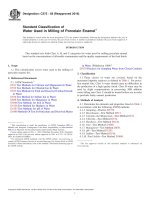
NOTE 1—SI Equivalents (Dimensions are in inchs.)
8.1 Steel Straightedge, stiff, having sufficient length to span
the diagonal of the largest shape to be measured, and graduated
in 0.02-in. (0.5-mm) divisions.
8.2 Measuring Wedges, two, steel, 2.5-in. (64-mm) long by
0.5 in. (13 mm) wide by 0.5 in. thick at one end, and tapered
from a line 0.5 in. from one end to zero thickness at the other
in.
mm
0.5
2.5
13
64
FIG. 1 Measuring Wedge
2
C134 − 95 (2016)
11.2 Precision Square, 12 by 9 in. (305 by 229 mm).
11.3 Measuring Wedge, steel, 2.5 in. (64 mm) long by 0.5
in. (13 mm) wide by 0.5 in. thick at one end, and tapered from
a line 0.5 in. at one end to zero thickness at the other end. The
wedge shall be graduated and numbered along the slope to
show the thickness of the wedge between base AB and slope
AC in 0.02 in. (0.5 mm) divisions (Fig. 1).
12. Procedure
FIG. 2 Method of Measuring Warpage of a Concave Surface
12.1 Place the test specimen on the metal plate so that it
rests securely on a width face (Fig. 5).
12.2 Abut the square at about midpoint of the long dimension.
12.3 Insert the steel wedge at the point of maximum
departure between the square and brick surface (Fig. 5).
12.4 Read and record the deviation to the nearest 0.02 in.
(0.5 mm).
FIG. 3 Method of Measuring Warpage of a Convex Surface
12.5 Repeat the procedures in 12.2, 12.3, and 12.4 for the
opposite vertical face and each end.
12.6 Reposition the specimen to rest securely on a thickness
face.
12.7 Repeat the procedures in 12.2, 12.3, and 12.4 for both
major vertical faces and each end.
FIG. 4 Alternative Method of Measuring Warpage of a Convex
Surface
13. Report
where:
W = warpage, %,
R = wedge reading, in. (mm), and
D = length of diagonal, in. (mm).
13.1 Report the following:
13.1.1 Brick brand and nominal size.
13.1.2 Individual deviation obtained from each measured
face for each specimen in the sampling.
10.2 Consider the larger of the warpage figures as that of the
specimen. Report the warpage values for the individual specimens to two significant figures.
14. Precision and Bias
14.1 Precision:
14.1.1 Interlaboratory Test Program—An interlaboratory
study was conducted by six laboratories on ten specimens
using two replications and two duplicate runs on the same
specimen. The specimens were stiff mud extruded and pressed
super duty brick.
14.1.2 Repeatability—The maximum permissible difference
due to test error between two test results obtained by one
SQUARENESS OF REFRACTORY BRICK
11. Apparatus
11.1 Metal Plate, 24 by 24 by 1-in. (610 by 610 by 25 mm)
thick, with one surface ground to a flatness of 60.005 in. (0.13
mm), or an equivalent abrasion-resistant flat surface.
A—Width face
B—Thickness face
C—End face
FIG. 5 Method of Measuring Squareness
3
C134 − 95 (2016)
TABLE 1 Precision Statistics
Precision Data
Attribute
Average,
in.
Length
8.941
Width
4.356
Thickness
2.96
Diagonal Warpage
0.265
Squareness of Width
0.022
Squareness Max
0.04
Deviation Midpoint of
Length
Squareness Max
0.032
Deviation Midpoint of
Thickness
Squareness Max
0.034
Deviation Midpoint of
Width
10 High Stack Oriented 29.83
10 High Stack Random 29.83
Bulk Density Pounds 138.036
per Cubic Foot
Relative Precision Data
Std.
Deviation
within
Lab Sr
Std. Deviation
between
Lab SR
Repeatability
Interval
Reproducibility
Interval R
Within
Lab Vr
Between
Lab VR
Relative
Repeatability,
%r
Relative
Reproducibility,
%R
0.007
0.007
0.01
0.079
0.011
0.018
0.01
0.011
0.01
0.124
0.015
0.019
0.017
0.017
0.02
0.22
0.035
0.053
0.028
0.027
0.02
0.348
0.043
0.056
0.072
0.135
0.020
30.099
69.39
50.043
0.11
0.227
0.25
52.529
84.731
53.23
0.199
0.38
0.56
84.277
194.29
140.121
0.308
0.631
0.69
147.08
237.247
149.045
0.012
0.012
0.032
0.039
36.413
44.168
101.96
123.67
0.01
0.011
0.027
0.034
29.549
36.674
82.736
0.02
0.02
0.427
0.04
0.03
0.729
0.04
0.06
1.196
0.1
0.9
2.046
0.05
0.07
0.31
0.12
0.11
0.529
0.14
0.19
0.866
99.89
0.35
0.30
1.482
given in Table 1. Two test results that do not differ by more
than the reproducibility interval will be considered the same
and, conversely, two test results that do differ by more than the
reproducibility interval will be considered different.
operator on the same material is given by the repeatability
interval and the relative repeatability interval (coefficient of
variation). The 95% repeatbility intervals are given in Table 1.
Two test results that do not differ by more than the repeatability
interval will be considered the same, and, conversely, two test
results that do differ by more than the repeatability interval will
be considered different.
14.1.3 Reproducibility—The maximum permissible difference due to test error between two test results obtained by two
operators in different laboratories on the same type of material
using the same type of test equipment is given by the
reproducibility interval and relative reproducibility interval
(coefficient of variation). The 95 % reproducibility intervals are
14.2 Bias—No justifiable bias statement is possible since
the true values of the properties of the reference material are
not defined.
15. Keywords
15.1 bulk density; dimension; insulating firebrick; refractories; size; squareness; warpage
ASTM International takes no position respecting the validity of any patent rights asserted in connection with any item mentioned
in this standard. Users of this standard are expressly advised that determination of the validity of any such patent rights, and the risk
of infringement of such rights, are entirely their own responsibility.
This standard is subject to revision at any time by the responsible technical committee and must be reviewed every five years and
if not revised, either reapproved or withdrawn. Your comments are invited either for revision of this standard or for additional standards
and should be addressed to ASTM International Headquarters. Your comments will receive careful consideration at a meeting of the
responsible technical committee, which you may attend. If you feel that your comments have not received a fair hearing you should
make your views known to the ASTM Committee on Standards, at the address shown below.
This standard is copyrighted by ASTM International, 100 Barr Harbor Drive, PO Box C700, West Conshohocken, PA 19428-2959,
United States. Individual reprints (single or multiple copies) of this standard may be obtained by contacting ASTM at the above
address or at 610-832-9585 (phone), 610-832-9555 (fax), or (e-mail); or through the ASTM website
(www.astm.org). Permission rights to photocopy the standard may also be secured from the Copyright Clearance Center, 222
Rosewood Drive, Danvers, MA 01923, Tel: (978) 646-2600; />
4