neural network retinal model real time implementation
Bạn đang xem bản rút gọn của tài liệu. Xem và tải ngay bản đầy đủ của tài liệu tại đây (935.68 KB, 24 trang )
REPORT
DOCUMENTATO
ADA255
652
,
' m
-
Ill
IIII
1! 11 III
I11
IIi 11111
iIll
"
'-
-'
SUrtsemOue
Ma"Wrese
wE
ted Ps unaumn
I
.AGENCY
USE
ONLY
(Leew
bIenbo
2.
REPORT
DATE
2.REPORT
TYPE
AND DATES
COVERED
02
September
1992
FINAL
REPORT 8/14/91-8/31/92
4.
TILE
AND
SUBTITLE
L
FUNDING
NUMBERS
Neural
Network
Retinal
Model
Real
Time
Implementation
(Neural
Network
Retinal
Model)
Contract
IDAAHO1-91-C-R240
AUTHOR(S)
Dr.
Robert
W.
Means
7.
PERFORMING
ORGANIZATION
NAME(S)
A
rEQA8
7
PERFORMING
ORGANIZATION
HNC,
Inc.
"''
REPORT
NUMBER
5501
Oberlin
Drive
3405-F-92
San
Diego,
CA
9212134
F
9SPONSORINGMONITORING
AGENCY
NAME(S)
AND
ADDRES(ES)
10.
SPONSRINGJMONITORING
Defense
Advanced
Research
Projects Agency
(DOD)
AGENCY
REPORT
NUMBER
1400
Wilson
Avenue
I
ArlIington,
VA
22209-2308
11.
SUPPLEMENTARY
NOTES
12&
DISTRIBUTIONAVAILABIUTY
STATEMENT
12b.
DISTRIBUTION CODE
Unrestricted
j
13.
ABSTRACT
(Mrxinma
D
worb)
L,
_
The
solution
of
complex
image
processing
problems,
both military
and
commercial,
are
expected
to
benefit
significantly
from
research
onto biological
vision
systems.
However,
current
development
of
biological
models
of
vision
are
hampered
by
lack
of
low-cost,
high-performance,
computing
hardware that
addresses
I
the
specific
needs
of
vision processing.
The
goal
of
this
SBIR
Phase
I
project
has
been
to
take
a
significant
I N
neural network
vision application
and
to
map
it
onto
dedicated
hardware
for
real time
implementation.
The
C
neural
network
was
already
demonstrated
using
software
simulation
on
a
general
purpose
computer.
During
Phase
I.
HNC
took a neural
network
model
of
the
retina and,
using
HNC's
Vision
Processor
(ViP)
prototype
hardware,
achieved
a
speedup factor
of
200
over
the
retina
algorithm
executed
on
the
Sun
SPARCstation.
A
performance
enhancement
of
this
magnitude
on
a
very
general
model
demonstrates
that
the
door
is
open
to
a
new
generation
of
vision
research
and
applications.
The
model is
described
along
with
the
digital
hardware
implementation
of
the
algorithm
using the
new
ViP
chip
seL
14.
SUBJECT
TERMS
15.
NUMBER
OF PAGES
Neural Network,
Vision,
Retina,
Tracking,
Real-Time,
Hardware
23
II.
PRICE
CODE
17.
SECURITY
CLASSIFICATION
11. SECURITY
CLASSIFICATION
1,.
SECURITY CLASSIFICATION
20.
UMITATION
OF
OF
REPORT
OF
TM
PAGE
OF ABSTRACT
ABSTRACT
Unclassified
Unclassified
Unclassified
Unlimited
F" no" II
S
MW
fm
=
t.
*4i
92I9
16
SL
3
i
I92
9
16
033
"
I
I
Neural
Network
Retinal
Model
Real
Time
Implementation
Acvuqaion
For
Final
Report
-I
, :
: .
3
2
September
1992
I_,_
Di
tr! btIsn/
or
i
Av
ti.abi11ty
c'
"
-
I
Ail
and/or
.Dist
Special
Sponsored
By:
Defense
Advanced
Research
Projects
Agency
(DOD)
_
Defense Small
Business
Innovation
Research
Program
ARPA
Order
No.
5916
Issued
by
U.S.
Army
Missile
Command
Under
L,1-C
QUATy
rN
CTe
D
3
Contract
#
DAAH01-91-C-R240
HNC,
Inc.
Dr.
Robert
W.
Means
5501
Oberlin
Dr.
619-546-8877
San
Diego,
CA
92121
Neural
Network
Retinal Model
14
August,
1991
August
14,
1991
-
August
31,
1992
*
DISCLAIMER
The
views
and
conclusions
contained
in
this
document
are
those
of
the authors
and
should
not
be
interpreted
as
representing
the
official
policies,
either
express
or
implied
of
the
Defense
Advanced
Research
Projects
Agency
or
the
U.
S.
Government
II
I
I
TABLE
OF
CONTENTS
I
1.0
Executive
Summary
3
2.0
Neural Network
Retinal
Model
4
2.1
Biological Background
4
I
2.1.1
Retina
Model
Dynamics
5
2.2
Processing
Layers
5
2.2.1
Photoreceptor
Layer
8
2.2.2
Horizontal
Layer
8
2.2.3
Bipolar
Layer
8
2.2.4
Amacrine
Layer
10
2.2.5
Ganglion
Layer
10
2.2.6
History
Layer
10
3.0
Vision
Processor
(ViP)
Hardware
15
3.1
ViP
Software
Description
19
4.0
Performance
of
the
Retinal
Model
Implementation
on
the
ViP
Hardware
19
5.0
Future
Tracking
Application
Systems
21
6.0
References
23
2
.I
I
I
1.0
Executive
Summary
The
solution
of
complex
image
processing
problems,
both
military
and
commercial,
are
expected
to
benefit
significantly
from
research
into
biological
vision
systems.
However,
current
development
of
biological
models
of
vision
are
hampered
by
lack
of
low-cost,
high-performance,
computing
hardware
that
addresses
the
specific
needs
of
vision
processing.
The
goal
of
this
SBIR
Phase
I
project
has
been
to
take
a
significant
neural
network
vision
application
and
to
map
it
onto
dedicated
hardware
for
real
time
implementation.
The
neural
network
was
already
demonstrated
using
software
simulation
on
a
general
purpose
computer.
During
Phase
I,
HNC
took
the
neural
network
model
of
the
retina
that
was
first
developed
by
Eeckman,
Colvin,
and
Axelrod
at
Lawrence
Livermore
National
Laboratory
1
and,
using
HNC's
Vision
Processor
(ViP)
hardware
achieved
a
speedup
factor
of
200
over
the
algorithm
executed
on
the
Sun
SPARCstation.
A
performance
enhancement
of
this
magnitude
on
a
very
general
model
demonstrates
that
the
door
is
open
to
a
new
generation
of
vision
research
and
applications.
With
HNC's
new
hardware,
developers
will
be
able
to
modify
parameters
in
their
model
in
close
to
real
time.
Complex
neural
network
models
of
the
human
visual
processing
system
have
previously
been
implemented
in
software
or
have
not
been
implemented
at
all
because
no
inexpensive
efficient
hardware
has
been
available
to
implement
the
large
connection
windows
postulated
in
most
models.
The
same
situation
exists
with
respect
to
large
convolution
kernels
or
connection
windows
in
conventional
Timage
processing.
The
large
increase
in
pnwessing
time
usually
encountered
when
the
kernel
size
increases
beyond
a
certain
size
has
led
researchers
and
users
to
develop
their
algorithms
and
applications
with
small
kernels.
This
has
been
true
in
spite
of
the
better
Iperformance
of
larger
kernel
algorithms
such as
the
edge
enhancement
algorithm
using
the
Laplacian
of
Gaussian
kernel
whose
performance
is
less
noise
dependent
when
the
kernel
size
becomes
7
x
7
or
larger.
HNCs
new
VLSI
chip
set
will
halt
this
computational
bias
against
larger
kernels
and
connection
windows.
All
other
hardware
chips
have
a
fixed
limit
to
the
size
of
the
connection
window.
Usually
this
limit
is
3x3
or
at
most
8x8.
The
alternative
for
the
algorithm
developer
is
to
take
excessive
time
in
a
software
implementation
or,
if
they
have
a
hardware
board
that
performs
small
convolutions,
to
build
a
new
piece
of
hardware
with
multiple
chips.
With
the
ViP
chip set,
a
l6x16
convolution
will
now
take
only
four
times
as
long
as
an
8x8
convolution
instead
of
taking
hundreds
or
thousands
of
times
longer
in
software
or,
alternatively,
taking
months
to
design
and
build
new
hardware
using
multiple
small
kernel
convolution
chips.
The
retinal
model
is
used
to
implement
and
evaluate
a
tracking
application
on
the
HNC
real
time
VLSI
Vision
Processor
(ViP).
The
algorithm
operates
well
at
low
signal
to
noise
ratio.
The
model
is
described
along
with
the
digital
hardware
implementation
of
Ithe
algorithm
using
the
new
ViP?
chip
set.
I
3
I
I
In
Phase
II,
HNC
plans
to
propose
the
insertion
of
the
ViP
hardware
into
a
specific
military
tracking
application
using
the
neural
network
retinal
modeL
2.0
Neural
Network
Retinal
Model
3
The
retina
model
consists
of
a
number
of
layers
of
processing
elements,
or
cells,
that
are
connected
to
previous
layers.
These
are
simple
feedforward
neural
networks.
There
are
also
cells
that
have
lateral
connections
within
the
layers.
The
feedforward
connections
_I
are
either
inhibitory
or
excitatory.
Each
cell
in
one
layer
is
connected
to a
small
number
of
cells
in
a
previous
layer.
This
connection
pattern
is
reproduced
for
each
cell
in
the
whole
layer.
The
firit
layer
of
cells
consists
of
the
pixels
or
the
image
sensors
themselves.
Each
I
succeeding
layer
of
cells
is
connected
to
its
previous
layer
or
layers
by
a
convolution
kernel
plus
a non-linear,
pointwise
transformation.
The
inclusion
of
inhibitory
or
excitatory
layers
requires
an
operation
equivalent
to
image
addition
or
subtraction.
These
signal
processing
operations
(convolution,
image
addition,
image
subtraction,
pointwise
nonlinear
transformations)
are
precisely
those
that
the
HNC
ViP
hardware
is
designed
to
perforI.
The
primary
function
that the
retinal
model
performs
is noise
reduction
and
motion
detection.
It
represses
both
noise
and
stationary
objects.
It
does
this
for
multiple
objects
in
the
field
of
view
with
no
increase
in
computational
load
over
a
single
object
The
model
was
originally
coded
in
C at Lawrence
Livermore
National
Laboratories
and
run
on
a
Sun
SPARCstation.
The
model
runs
slowly
on
the Sun,
taking
several
seconds
for
a
single
128x128
image
to
pass
through
all
five
layers
of
the
retina.
HNCs
task
in
Phase
I
was
to
take
the
model
and
to
map
it
efficiently
onto
our
ViP
hardware.
The
retinal
model
is
described
in
more
detail
in
reference
1
and
in
a
paper to
be
published
by
Eeckman,
Colvin
and
Axelrod.
A
summary
of
the
model
is
given
in
section
2.1.
2.1
Biological
Background
To
animals
and
humans,
the
detection
and
tracking
of
small
moving
targets
in
high
noise
environments
is
effortless
and
virtually
instantaneous.
This
task
is
done
without
the
higher
cognitive
facilities
of
the
brain
being
used.
The
processing
that
occurs
is
non-
adaptive.
Therefore,
to
design
a
tracking
system,
it
is
logical
to
examine
the
processing
that
occurs
early
in
the
visual
system,
(i.e.,
in
the
retinal
system)
and
to
build
a
similar
software
or
hardware
model.
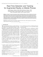
The
retina
of
vertebrates
consists
of
five main
cell
types
as
illustrated
in
Figure
1
(taken from
reference
1).
Three
of
these
cell
types,
photoreceptors,
bipolar
cells
and
ganglion
cells,
are
in
a
direct
feedforward
path from the
incoming
light
to
the
visual
cortex
of
the
brain.
The
remaining
two
types, horizontal
cells
and
amacrine
cells,
laterally
interact
with
layers
of
photoreceptors,
bipolar
cells
and
ganglion
cells.
4
I
I
2.1.1
Retina
Model
Dynamics
I
In the
retina
model,
image
processing
operations
are
done
by
a
functional
layer
of
identical
cells.
These
transformations
between
layers
correspond
to
filters
that
perform
two
dimensional
spatial
operations
on
the
data.
These
operations
can
have a
different
I
spatial extent
in
every
layer.
The
temporal
processing
in
the
retina
is
primarily
decay
of
the
input
stimulus
and
delay
of
the
feedback
or
feedforward
outputs
from
one
layer
to
another.
The
number
of
distinct
mathematical
operations needed
to
model
the
retina
is
small.
The
operations
symbolized
in
Figure
2
are
sufficient.
The
temporal
behavior
of
the
neurons
is
modeled as
a
leaky
integrator.
The
photoreceptor
cell
response
is
typical
of
most neurons
and
is
given
by
the
equation::
3
PR4
(t)
=
a
PR4
(t-
1)
+
f[input_
image4
(t)]
where
alpha
is
a
decay
constant
and
fl]
is
a
non-linear
transfer
function,
usually
a
sigmoidal
or
threshold
function.
The
photoreceptor
cells
are
also
connected
to
their
neighboring
photoreceptor cells.
The
latter
connections
are
modelled
by
a
convolution
3
over
the
spatial
neighborhood
with
a
kernel
whose
weights
represent
coupling
factors.
PR.,.(t)=,
K4
PR._(t)
where
the kernel,
K
is
defined
over
a
finite
neighborhood.
These
two
transformations
(temporal
and
spatial)
of
the
input
image
are
implemented
sequentially.
Figures
3
through
7
describe
the
processing
in
each
layer
of
the
retina
using
the
symbols
of
Figure
2.
2.2
Processing
Layers
There
are
five
layers
of
neurons
in
the
retinal
model
corresponding
to
the
five
layers
in
the
biological
model
shown
in
Figure
1
In
addition,
there
is
a
sixth
layer
modeled
that
permits
the
result
of
the
processing
to
be
displayed
in
a
meaningful
manner
to
a
human
observer.
The
sixth
layer
shows
the
history
of
the
track
of
a
moving
object.
All
the
processing
in
each
layer
can be
performed
on
the
ViP?.
Each
layer
of
neurons
in
the
retinal
model
is
considered
to
be
equivalent
to
an
image.
Each
pixel
in
the
image
corresponds
to
a
neuron
in
the
layer.
The value
of
each
pixel
is
identical
to
the
output
value
of
its
corresponding
neuron.
Each
basic
operation,
whether
it
is
a
subtraction
of
two
layers,
a multiplication
of
a
layer by a decay
constant,
a
thresholding
of
a
layer,
a
non-linear
transform
of
a
layer
or
a
feedforward
transform
between
two
layers
takes
a
single
pass
of
the
image
through
the ViP
chip
set.
5
I
Photoreceptor
Cells
IiolrCls
Hrzna
el
0mcrn
Cel
Icn
Cel
=,OO
Figure
1.
Ccli
types
of
the
veetxte
atina
6
a
*
Multiplication
by
a
-
4.
Addition
Subtraction
(left Input-
bottom
Input)
Kb
O
Convolution
with
kernel
KU
I7[]
Non-Unear
transfer
function
Figure
2:
Symbol
table for
Figures
3
through
7.
The
constants
a
and
Kij
are
different
for
each
layer.
7
All
pixels
in
a
given
layer
undergo
the
same
arithmetic
operations
in
parallel.
The
feedforward
transform
between
a
source
and
destination
layer
is
done
by
convolving
a
connectivity
kernel
with
the
source
image
to
produce
the
destination
image.
Each
layer
in
the
model
receives
a
time series
of
images
from
the
previous
layer
or
layers
as shown
in
Figure
1.
Within
each
layer
there
are
several
intermediate
processing steps.
2.2.1
Photoreceptor
Layer
The
photoreceptor
layer receives
the light
input
directly.
In
the
hardware
implementation
this
layer
receives
a
time
sequence
of
images
directly from
a
camera
or
from
images
read
from
disk.
A
nonlinear
transformation
is
performed
on the
input
light
image
by
passing
it
through
a
look-up
table
on
the
ViP. This
transformed
image
(like
all
images)
is
considered
as
a
layer
of
neurons
and
stored
in
memory
as
an
image
in
the
ViP.
The
output
image
of
the
photoreceptor
layer
from
the
previous
time
step
is
multiplied
by
a
decay
constant
and
stored
in
memory.
The
transformed
light
and
the
decayed
photoreceptor
output
images
are
added
together
and
stored
in
memory. This
image
is
then
convolved
spatially
with
a
connectivity
kernel
to
form
the
output
of
the
photoreceptor
layer.
The
photoreceptor
kernel smears
the
input
image
and
reduces
the
effects
of
noise.
Figure
3
is
a
block
diagram
of
the
processing
described.
2.2.2
Horizontal
Layer
The
horizontal
layer
receives
input
from
the
photoreceptor
layer.
A
nonlinear
transformation
is
performed
on
the
input
by
passing
it
through
a
look-up
table
on
the
ViP
and
storing it
in
memory. The output
image
of
the
horizontal
layer
from the
previous
time
step
is
multiplied
by
a
decay
constant
and
also
stored
in
memory.
These
two
resultant
images are
then
added
together
to form
the
output
of
the
horizontal
layer.
The
horizontal
layer
will
eliminate
the
effect
of
a background
that
has
a
small
spatial
gradient.
Figure
4
is
a
block
diagram
of
the
processing
described.
2.2.3
Bipolar
Layer
The
bipolar
layer
receives
input from
both
the
horizontal
layer
and
the
receptor
layer.
The
horizontal
layer is
convolved
spatially with
an
inhibitory
kernel
to
form
an
intermediate
inhibitory image.
The
receptor
layer
is
convolved
spatially
with
an
excitatory
kernel
to
form
an
intermediate
excitatory
image.
These
two
images
are
combined
by
subtracting
the
inhibitory
result
from
the
excitatory
result.
These
two
convolutions
represent
an
on-center,
off-surround
connection
to
the
receptor
and
horizontal
neurons
respectively.
The
output
image
of
the
bipolar
layer
from
the
previous
time step
is
multiplied
by
a
decay
constant
and
added
to
the
excitatory
and
inhibitory
result.
That
result
is
then
averaged
spatially
by
convolution
and
stored
as
the
output
of
the
bipolar
layer.
Figure
5
is
a
block
diagram
of
the
processing
described.
8
I
K.
IR i
I
Figure
3.
Photoreceptor
layer
processing.
It(t)
is
the
incident
light. PR
(t-1)
is
the
output
of
the
photoreceptor
layer at
the
previous
time
step.
I
HP.
(-1)
H
+
(t)
Figure
4.
Horizontal
layer processing.
9
2.2.4
Amacrine
Layer
The
amacrine
layer
is an
inhibitory
layer
for
the
later
ganglion
layer.
It
receives
its
input
from
the
bipolar
layer.
The
absolute
value
of
the
difference
between
the
bipolar
outputs
at
time,
t,
and
time,
t
-
delay,
is
computed.
This
step
is
essentially
a motion
detection.
The
output
of
the amacrine
layer
from
the
previous
time
step
is
multiplied
by
a
decay constant
and
added
to
the
absolute
difference
result
and
then
thresholded.
The
previous
three layers
have
dealt
primarily
with
spatial
processing
noise
reduction;
the
amacrine
and
ganglion
layer
deal
primarily
with
temporal
processing.
Figure
6
is
a block
diagram
of
the
processing
described.
2.2.5
Ganglion
Layer
The
ganglion
layer
receives
excitatory
input
from the
bipolar
layer
and receives
inhibitory
input
from
the
amacrine
layer.
Excitatory
input
is
received
homogeneously
from
the
ganglion
neuron's
nearest
neighbors
in
the
bipolar
layer.
However,
inhibitory
input
is
received
from
neurons
in
the
amacrine
layer
(which
was
a
motion
detection
layer)
only
in a
preferred
direction.
The
two
connectivity
kernels
are
shown
in
Figure
7.
Nine
amacrine
neurons
in
three
concentric
arcs
centered
around
one
of
the
six
axes
of
the
hexagon
contribute
inhibition
along
that
axis.
The
hexagonal
structure
of
the
cells
in
a
layer
must
be
mapped
carefully
into
a
rectangular
convolution
kernel
by
the
mapping
illustrated
in
Figure
7.
As
long
as
the
coupling
factor
for
pixels
at
a
given
row
and column
are
mapped
into
corresponding
weights
in
the
kernel,
then
the
model
is
preserved.
The
inhibitory
and
excitatory
convolution
results
are
combined
by
subtracting
the
inhibitory
result
from
the
excitatory
result.
The
output
image
of
the
ganglion
layer
from
the
previous
time
step
is
multiplied
by
a
decay
constant, added
to
the
excitatory
and
inhibitory
result
and
then
thresholded.
The
ganglion
layer
detects
objects that
are
moving
in
a
direction
not
inhibited
by
the
amacrine
layer.
Figure
8
is
a
block diagram
of
the processing
described. There
can
be
six
different
ganglion
layers
in
the
model
each
one
with a
different
inhibitory
kernel
aligned
along
one
of
the
hexagonal
axes.
The times
in
table
2
were
calculated
with
a
single
ganglion
layer.
Processing
all
six
direction
will
approximately
double
the
times.
2.2.6
History
Layer
The
history
layer
does
not
correspond
to
a
layer
of
neurons
in
the
retina.
It
is
a
convenient
way
to
accumulate
spikes
from
the
ganglion
layer
and
display
the
tracks
of
moving
objects.
10
I~ej
IRi
Ii
w
Figure
5.
Bipolar layer
processing.
I
Figure
6.
Amacrine
layer
processing.
0
0 0
0 0
0
0
0
0
0
0
0
0
0
0
0
2
6
30
0 0
0
0
2 6
30
x 0 0 0
0
2
6
30
0
0
0
0
0
0 0
0 0
0
0
0 0
0
0
0
0 0
0
(7a)
Hexagonal
pattern
of
inhibitory
coupling
between
amacrine
and
ganglion
layer.
0
0 0
0
0
0
0 0
0
0
0 0
0
0 2 6
30
0 0
0
2
6
30
0
0
0
0
2
6
30
0
0
0
0 0
0
0 0 0
0
0 0 0 0
0
0
0
(7b)
Inhibitory
kernel
corresponding
to
(7a)
directional
coupling.
Figure
7.
Connectivity
kernels
in
the
Ganglion
layer.
12
I
I
0 0 4
4
4 4
0
0
0
4
10
10
10
4
0
0 4
10
25
25
10 4
0
4
10 25
100
25
10
4
0
4
10
25
25
10
4
0
I
0
4
10
10 10
4
0
1
0
0 4
4
4 4 0
0
(7c)
Hexagonal
pattern
of
excitatory coupling
between bipolar
and ganglion
layer.
0
0
4
4
4
4
0
0
4
10
10
10
4
0
0
4
10
25
25
10
4
4
10
25
100
25
10
4
0
4
10
25
25
10
4
0
4
10
10
10
4
0
0
0
4 4
4
4
0
(7b)
Excitatory
kernel
corresponding
to
(7c) uniform coupling.
Figure
7.
Connectivity kernels
in
the
Ganglion layer.
13
IK
Ii
EAI
Iq
G!I)
t
It
Sgr
.Gnlo
ae
rcsig
I1
3.0
Vision
Processor
(VIP)
Hardware
The
ViP
is
a
new
type
of
high
performance
systolic
array
VLSI
chip
set
optimized
for
advanced
vision
processing.
It
is
able
to
perform
very
high
speed
conventional
and
neural
network
image
processing
functions
as
well
as
image
arithmetic (e.g.,
subtract
two
images).
The
ViP
consists
of
two
digital
VLSI
chips that
can
efficiently
perform
two
dimensional
convolution
with
arbitrary sized
kernels
with
full
utilization
of
its
processing
resources.
For
small kernels,
the
ViP
chip
set
performs
convolutions
at
a
throughput
rate
of
40
megapixels
per
second
on 8-bit
pixels.
For
larger
kernels,
performance
is
inversely
proportional
to
the
kernel
size.
The
has
64
processing
elements
arranged
in
an
8x8
systolic
array
that
can
perform
convolutions
with
very
large kernels
(up
to
64x64)
on
images
up
to
4096x4096.
Unlike
other
image
processors,
the
ViP
maintains
its
full
efficiency
(5.12
billion
arithmetic
operations
per second)
on
large
kernels.
An
8x8
convolution
on
a
512x512
image
requires
less
than
7
milliseconds.
Dual
image
arithmetic
and
logical
operations
are
processed
at
the pixel
memory
access rate
of
80
megapixels per
second.
The
chip
set
also
has
the
capability
to
perform
convolutions
on
images
with
16-
bit
pixels at
20
million
pixels
per
second.
The
ViP
chip
set
has been
designed
into a
daughterboard
that
attaches
to
HNC's
Balboa
860/VME
coprocessor
board
through
an
expansion
bus.
The Balboa
860/VME
is
a
high
performance
coprocessor
based
on
Intel's
i860
64-bit
RISC
microprocessor.
It
provides
a
40
MHz
Intel
i860
with
16
Mbyte
of
DRAM
memory
and
uses a
64-bit
architecture
to
provide
a
peak
processing
performance
of
40
MIPS
and
80
MFLOPS.
Block
diagrams
of
the
daughter
board
and
the
Balboa
are
shown
in
Figures
9
and
10.
The ViP
daughterboard
contains
both the
ViP-I
and
the
ViP-2
chips.
The
ViP-I
performs
the
convolutional
and
morphological
operations.
Image
arithmetic
is
performed
in
the
ViP-2
chip. The
ViP
daughterboard
contains
three
banks
of
image
memory
with
four
megabytes
of
DRAM
per
bank.
There
is
also
a
kernel
memory containing
64
Kbytes
of
fast
static
RAM.
The
resources
of
the
Balboa
combined
with
the
image
processing
capability
of
the
ViP
offers
a
high
performance
component
for
a
wide
range
of
image
analysis
and
processing
applications.
The ViP image
memory
interface
is
designed
such
that
a
conventional
linear
memory
architecture
can
be
used
for
accessing
and
storing
data.
No
variable
length
scan
conversion
shift
registers
are
needed
by
the
systolic
array
to
access
an
image
stored
in
a
conventional
raster
scan
format.
Such
scan
conversion
variable
length shift
registers are
often
required with
other
convolution
architectures.
The
images
are stored
in
the three
banks
of
dynamic
RAM
on
the
daughterboard.
The
banks
of
dynamic
RAM
are
linked
to
the
Balboa
860/VME
memory
through
the
Balboa
860/VME's
expansion
connector.
This
allows
direct
access
via
DMA
between
the
ViP
memory
and
the
Balboa
860/VME's
16
MBytes
of
DRAM.
It
also
allows
the ViP
to
access
data
across
the
VME
Subsystem Bus
(VSB)
bus
where
other
VSB
hardware
such
15
as a
frame
grabber
can reside
To
facilitate
these
transfers,
the
ViP-2
has
an
on-chip
DMA
controller.
The
DMA
controller
on the
ViP-2
can
be
transferring
one
image
between
the
frame
grabber
and
a
bank
of
DRAM
while,
at
the
same
time,
the
ViP
chip set
is
doing
a
convolution
or
other
image
processing
operation
on
another
image.
This
flexibility
and
parallelism
provides
the
ViP
daughterboard
with
the
processing
and
data
transfer
bandwidths
needed
to
perform
real
time
image
processing.
x
p
VIP
a
2/
MB
Intel
i860
n
Daughtercard
I
RM
RMDRAM
2
Control
f
i860
Memory
Bus
(160
MBPS,
64-Bit
A
ch)j
ArMEBu
biter
lInterru
p
4
x
M
M,),Master/Sla
a
IIP
M
~
-
P€/ I
-Bit,
Asynh,
10
MI/Sec
Bus
IIdl
slot
IRS-231
EPRO
Real
T
SYstem
w
Br
/E
Options
I1
/I
12
KB31
Clocks
11
Reset
IIon
JlYAG)l
Figure
9.
Block
diagram
of
ViP
Daughterboard.
16
WegtIA
I4W6
IL-
I~
__________
VEP-2-
30i860
Lookp
Lokup
ontrller32
I
Tale
TbleTable
I8
f
8
-r8
I/O
Piel
Interface
I32
f321
32
Image
RAM
Block
Image
R
AM
Block
IgeRAM
Block
IA4Megabyts
B4
Meab
-s
9
1=C4eMa
s
I
Figure
10.
Block
diagram
of
Balboa
860/VME.
I
17
The
ViP
chip
set
is
particularly
well
suited
for
neural
network
and
preattentive
vision
image
processing
algorithms
that
use
large
connected
neighborhoods
to
model
the
transformations
between
layers
of
neurons.
Many
of
these
algorithms
use
convolution
extensively
in
the neural
network
model.
One
of
the
primary
advantages
of
the
ViP
architecture
is
its
ability
to
implement
large
kernel
convolution
at
full
efficiency.
This
feature
of
the
ViP
is
very
important
for
research applications
in
which
the
required
kernel
sizes
are
not
known
a
priori.
In
such
applications,
the
ViP
allows
tremendous
flexibility
without
sacrificing
performance.
Table
1
compares
the
ViP's
convolution
performance
on
a
512x512
8-bit
image
with
other
commercially
available
image
processing
chips.
Notice
that
for
kernels
larger
than
8x8,
all
of
the
other
convolution
chips
require
multiple
chips
to
perform
the
operation.
In
practice,
this
means
that
using
one
of
these
other
chips
restricts
the
user
to
small
kernels.
The
alternative is
to
take
excessive
time
in
a
software
implementation
or
to
build
a
new
piece
of
hardware
with
multiple
chips.
Table
1.
Comparison
of
ViP
daughterboard
convolution
performance
with
other
leading
convolution
chips.
All
times
are
in
milliseconds
and
the
image
is
512x512
with
8-bit
gray-
scale.
Window
Sun
SPARC
Plessey
Inmos
LSI
Logic
HNC ViP
Size
Station
PDSP
16488
IMSAI
10
L64240
Daughterboard
3x3
2,000
6.6
13.1
13.1
6.6
8x8
14,000
26.2
6
chips
13.1
6.6
16x16
56,000
8
chips
18
chips
8
chips
26.2
32x32
224,000
not
possible
60
chips
32
chips
104.9
64x64
896,000
not
possible
220
chips
128
chips
419.6
The
key
to
the
ViP's
convolution
capability
is
a
novel
two
dimensional
systolic
array
architecture
on
the
ViP-I
chip.
Systolic
array
architecture
have been
proposed
and
developed
since
the late
1970s
for
a
variety
of
signal
and
image
processing
applications.
H.
T.
Kung,
in
a 1982
review
article
[41,
describes
and
classifies
systolic
arrays
of
many
different
types.
A
special
issue
of
the
July
1987
Computer
magazine
is
devoted
to
papers
that
review
systolic
array
projects
and
architectures.
For
many
applications,
systolic
arrays
of
processing
elements
are
a
very
effective
means
of
applying
multiple
processors
to
perform
computationally
intensive
tasks.
The
details
of
the
systolic
array
architecture
can
be
found
in
reference
5.
18
3.1
VIP
Software
Description
The
ViP
is
programmed
through
a
set
of
command
register
that
are
accessed
as
memory
locations
by
the
Balboa's i860
processor.
To
task
the
ViP
to
perform
a
function,
the
appropriate
control
words
are
written
to
the
various
registers
and
the
GO
bit
is
set.
At
this
point
the
ViP-1
and
ViP-2
internal
state machines
begin
execution.
No
additional
intervention
by
the
Balboa
is
necessary
until
the
function
is
complete.
Completion
is
signaled
by
an
interrupt to
the
Balboa.
Users
can
access
the
control
register
to
directly
program
the
ViP;
however,
this
approach
requires
detailed
knowledge
of
the
control
registers
and
their
interactions.
To
I
aid
users
in
developing
software
for
the
ViP,
an
image
processing
module
software
(IPMS)
library
is
provided that
implements
many
common
image
processing
functions.
The
library
contains
over
100
functions
including
image arithmetic,
Sobel
edge
operation,
binary
morphology,
chain
coding,
two
dimensional
Fourier
transforms,
and
image
histogram.
All
library
routines
are
callable
from
C
running
under
the
Balboa
Executive
or
running
directly
on
the
host system.
Some
operations,
like
the
Fourier
Transform,
operate
in
software
on
the
i860
processor.
These have
been included
in
IPMS
even
though
they
don't
run
on
the
ViP
hardware
in
order
to
provide
a
complete
image
processing
library.
4.0
Performance
of
the
Retinal
Model
Implementation
on
the
ViP
Hardware
The
retinal
model
is implemented
on the
system
shown
in
Figure
11.
The
primary
functions
that the
retinal
model
performs
is
noise
reduction
and
motion
detection.
It
represses
both
noise and
stationary
objects.
It
does
this
for
multiple
objects
in
the
field
of
view
with
no
increase
in
computational
load
over
a
single
object.
The
model
was
originally
coded
in
C
and
run on
a
Sun
SPARCstation.
The
model
runs
slowly
on
a
Sun,
taking
several
seconds
for
a
single
128x1
28
image
to
pass
through
all
five
layers
of
the
model.
Since
the
ViP
operates
at
a
peak
processing
rate
of
40
Megapixels
per
second,
a
128x128
image
(or
layer
of
cells),
executes
a
single
operation
such
as
convolution
or
image
subtraction
is
410
microseconds.
Each
pass
of
an
image
through
the
entire
retinal
model
takes
32
ViP
operations.
These
operations
consist
solely
of
a sequence
of
the
following
functions:
convolution
with
a
kernel,
look-up
table
transformation
of
an
image,
addition
of
two
images,
subtraction
of
two
images,
multiplication
of
an image
by
a
constant,
absolute
value
of
the
difference
between
two
images and
threshold
of
an
image.
The
peak
frame
rate for
the
entire
retinal
model
using
a
single
ViP chip
set
is
approximately
75
frames
per
second,
although
software overhead,
and
slower components
such
as
a video
camera
will
limit
this
to
50
frames
per
second
or
less.
The
retinal
model
is
easily
pipelined
so
that
two
ViP
chip
sets
would
operate
at
100
frames
per
second
and
multiple
chip
sets
would
operate
at
even
higher
rates.
Images
larger
than
128
x
128
are
readily
processed
at
proportionally
lower
frame
rates.
19
ViP
fIage
Processing
Module
I
I
Camera
' HotDaughter
IDaughter
Frame
I
Fgure
11
Retinal
model
implementation
system
diagmmn
I20
I
A
performance
comparison
between
the
Sun
SPARCstation
IPC
software
only
system
and
the
ViP
is
given
in
Table
1.
The
ViP
controlled
by
dedicated
software
figures
are
projected.
The
Sun
only
and
the
ViP
controlled
by
Sun
software figures
are
measured.
Table
2.
Retinal
Model
Processing
Time
per
Image
Image
Size
Sun
Only
ViP
Controlled
by
ViP
Controlled
by
Sun
Software
Dedicated
Software
128x128
3.5
sec.
0.14
sec
0.021 sec
512x512
46.0
sec
0.36
sec
j
0.23
sec
All
operations on
the
ViP
chip
set are
initiated
by
software
function
calls
on
the
Sun
host.
A
message
packet
is
sent
by
the
host to the
Balboa
coprocessor
board.
The
i860
microprocessor
then
reads
the
message
packet
and
loads the
control
registers
on the
ViP
with
the
correct
values
for
the
operation
requested.
The
i860
keeps track
of
all
layer
parameters
and
manages
the
flow
of
images
between
the
banks
of
memory.
The
overhead
involved
in
message
passing,
interrupt
processing
and
resource
management
is,
at
present,
approximately
4
milliseconds
per
function
call.
A
preliminary
analysis has
shown
that
the
software
overhead
can
be
reduced to
less
than
250
microseconds
per
operation
so
that
it
is
only
a
fraction
of
the
ViP
hardware
image processing
time.
The
times
given
in
Table
2 for
the
ViP
Controlled
by
Dedicated
Software
assumed
the
250
microsecond
overhead
value.
The software
overhead
percentage
will
be
particularly
small
when
the
image
sizes are
large,
such
as
512
x
512.
In
that
case
the
hardware
processing
time
for
a
basic
ViP
operation
is
approximately
6.7
milliseconds,
but
the
software
overhead
will
remain
at
250
microseconds.
The
much
faster
speed
of
the
ViP
system
as
compared
to
the
Sun
only
system
greatly
facilitates
the investigation
of
the
many
coupling
parameters
and
decay constants
in
the
modeL
The
small
size
of
the chip
set
and
the
ease
of
programmability
means
that the
chip
set
can
be
used in
real
time
fielded
systems
after
algorithms
are
developed
and
tested
on
the
development
system
shown
in
Figure
11.
5.0
Future
Tracking
Application
Systems
Target
detection
and
tracking often
suffers
from
poor
signal-to-noise
ratio,
sometimes
described
as
clutter.
Visibic
or
infrared sensors
often
create
additional
signal
processing
problems
because
the
noise
distribution
is
non-Gaussian.
Active systems
such as
radar
and
ladar
often
have
reflections
from trees,
buildings
or
hills
that
may
be
misinterpreted
as
targets. The
effect
of
these
problems
can
be
reduced
or
eliminated by
preprocessing
the
image through
a
retinal
model.
Operationally,
the
poor
signal-to-noise
ratio
can
lead
to
false
alarms
and/or
missed
targets.
The
standard
approaches
used
to
separate the
target
from
the
noise
are
I
21
I
thresholding
and
integration
over
multiple
images.
These techniques
are
usually
only
partially
effective.
In
addition
to
thresholding
and
integration
over
images,
the retina
based model
uses
the
biologically-inspired
techniques
of
direction
sensitivity
and
local
I
neighborhood
area
of
interest processing.
The
latter
two
signal
processing techniques
can
be
implemented
in
neural
network
algorithms
that
exploit
the
parallel
hardware
architecture
of
the
ViP
chip.
The
inherently
parallel
nature
of
the
biologicaUy-inspired
algorithms
has
lead
HNC
to
develop
new,
very
efficient
parallel
hardware
that
can
implement
these
algorithms
in
the
latest
VLSI
technology.
The
combination
of
new
algorithms
and
new
technology
make
neural
network
approaches
particularly
well-suited
to applications
involving
the
detection
and
tracking
of
targets
in
a
cluttered
environment.
IHNC's
ViP
can
implement
complex
neural
network
models
of
the
human
visual
system
in
real
time.
Existing
convolutional
processors
are unable
to
accomplish
this
task
in
a
cost
effective
manner.
HNC's
new
VLSI
image
processing
ViP
chip,
solved
this
problem
with
a
new
patented
systolic
array
concept
(
US
Patent
#
5138695).
Prior
to
this,
models
have
primarily
been
implemented
in
software
or
have
not
been
implemented
at
all
because
no
inexpensive
efficient
hardware
has
been
available
to
implement
the
large
connection
windows
postulated
in
most
models.
The
same
situation
exists
with
respect
to
large
convolution
kernels
or
connection
windows
in
conventional
image
processing.
The
large
increase
in
processing
time
usually
encountered
when
the
kernel
size
increases
Sbeyond
a
certain
size
has
led
researchers
and
users to
develop
their
algorithms
and
applications
with
small
kernels.
The
availability
of
this
chip
should
lead
neural
network
and
image
processing
researchers
to
develop
and
test
increasingly
complex
and
powerful
algorithms
and
models
of
vision
and
apply
them
to
difficult
application
problems.
I
I
I2
I
6.0
References
[1]
Eeckman,
F.H.,
Colvin,
M.E.,
and
Axelrod,
T.S.,
"A
Retina-Like
Model
for
Motion
Detection",
hitemational
Joint
Conference
on
Neural
Networks,
Washington,
D.C.,
pp.
II-
247
to
11-249
(1989).
[2]
Daugman,
J.,
"Complete
Discrete
2-D
Gabor
Transforms
by
Neural Networks
for
Image
Analysis
and
Compression",
IEEE
Trans.
Acoustics,
Speech,
and
Signal
Processing,
36
(1988).
[3]
Hecht-Nielsen,
R.,
"Nearest
Matched
Filter
Classification
of
Spatiotemporal
Patterns",
Applied
Optics
26,
1892
(1987).
[4]
Kung,
H.T.,
"Why
Systolic
Architecture",
Vol.
15,
No.
1,
pp.
37-46,
Jan.
1982.
[5]
Means,
R.
W.,
"Systolic
Array
Architecture
of
a
New
VLSI
Vision
Chip",
Proceedings
of
the
SPIE,
San
Diego,
1991.
[6]
Grossberg,
S.
and
Mingolla,
E.,
"Neural
Dynamics
of
Perceptual
Grouping:
Textures,
Boundaries
and
Emergent
Segmentations",
Perception
and
Psychophysics,
38,
pp.
141-
171,
1985.
[7]
Tessier-Lavigne,
M.
and
Attwell,
D.,
"The
Effect
of
Photoreceptor
Coupling
and
Synapse
Nonlinearity
on
Signal:Noise
Ratio
in
Early
Visual
Processing",
Proc.
R.
Soc.
London,
Vol.
B
234,
pp.
171-197
(1988).
[8]
Barlow,
H.B.
and
Levick,
W.R.,
"The
Mechanism
of
Directionally
Selective
Units
in
the
Rabbit's
Retina",
J.
Physiol.
(London),
Vol.
178,
pp.
477-504
(1965).
[9]
Koch,
C.,
Poggio,
T.,
and
Torre,
V.,
"Retinal
Ganglion
Cells.
A
Functional
Interpretation
of
Dendritic
Morphology",
Phil.
Trans.
R.
Soc.
London,
Vol.
B
298,
pp.
227-264
(1982).
[101
Werblin,
F.S.,
Maguire,
G.,
Lukasiewicz,
P.,
Eliasof,
S.,
and
Wu,
S.,
"Neural
Interactions
Mediating
Detection
of
Motion
in
the
Retina
of
the
Tiger
Salamander",
Visual
Neurosci.,
Vol.
1,
pp.
317-329
(1988).
23