Astm c 1492 03 (2016)
Bạn đang xem bản rút gọn của tài liệu. Xem và tải ngay bản đầy đủ của tài liệu tại đây (420.71 KB, 7 trang )
Designation: C1492 − 03 (Reapproved 2016)
Standard Specification for
Concrete Roof Tile1
This standard is issued under the fixed designation C1492; the number immediately following the designation indicates the year of
original adoption or, in the case of revision, the year of last revision. A number in parentheses indicates the year of last reapproval. A
superscript epsilon (´) indicates an editorial change since the last revision or reapproval.
C67 Test Methods for Sampling and Testing Brick and
Structural Clay Tile
C90 Specification for Loadbearing Concrete Masonry Units
C140 Test Methods for Sampling and Testing Concrete
Masonry Units and Related Units
C150 Specification for Portland Cement
C260 Specification for Air-Entraining Admixtures for Concrete
C331 Specification for Lightweight Aggregates for Concrete
Masonry Units
C494/C494M Specification for Chemical Admixtures for
Concrete
C595 Specification for Blended Hydraulic Cements
C618 Specification for Coal Fly Ash and Raw or Calcined
Natural Pozzolan for Use in Concrete
C979 Specification for Pigments for Integrally Colored Concrete
C989 Specification for Slag Cement for Use in Concrete and
Mortars
C1157 Performance Specification for Hydraulic Cement
1. Scope
1.1 This specification covers concrete tiles intended for the
use as roof covering where durability and appearance are
required to provide a weather-resistant surface of specified
design.
1.2 Tiles are manufactured from portland cement, water,
and mineral aggregates with or without the inclusion of other
materials.
1.3 Tiles are shaped during manufacturing by molding,
pressing, or extrusion. The shaping method can be used to
describe the tile.
1.4 Other constituents, such as chemical and mineral admixtures established as suitable for use in concrete, shall conform
to ASTM standard specifications where applicable, or shall be
shown by tests or experience not to be detrimental to the
durability of concrete.
1.5 Tiles are generally planar or undulating rectangular
shapes available in a variety of cross-sectional areas profiles,
shapes, sizes, surface textures, and colors.
3. Terminology
NOTE 1—Concrete roof tiles covered by this specification are made
from lightweight or normal weight aggregates, or both.
NOTE 2—When particular features are desired, such as color, surface
texture for appearance, or other special features, such properties should be
specified by the purchaser. However. the local sellers should be consulted
as to the availability of concrete roof tile having a desired feature.
3.1 Definitions—The following terms are used in connection
with concrete roof tiles:
1.6 The values stated in inch-pound units are to be regarded
as standard. The values given in parentheses are mathematical
conversions to SI units that are provided for information only
and are not considered standard.
3.3 head lap—distance of overlap measured from the uppermost course to the point that it laps over the undermost
course.
3.2 batten lugs—protrusions on the underside of the tile
designed to engage over the upper edge of tiling battens.
3.4 high profile tile—tile with a rise to width ratio greater
than 1:5.
2. Referenced Documents
2.1 ASTM Standards:2
C33 Specification for Concrete Aggregates
3.5 interlocking tile—tiles with a system of ribs or grooves
enabling the lateral joining of adjacent tiles in the same
horizontal row, with the overlapping lock covering the underlapping lock.
1
This specification is under the jurisdiction of ASTM Committee C15 on
Manufactured Masonry Units and is the direct responsibility of Subcommittee
C15.06 on Roofing Tile.
Current edition approved Dec. 1, 2016. Published December 2016. Originally
published in 2001. Last previous edition approved in 2009 as C1492–01(2009).
DOI: 10.1520/C1492-03R16.
2
For referenced ASTM standards, visit the ASTM website, www.astm.org, or
contact ASTM Customer Service at For Annual Book of ASTM
Standards volume information, refer to the standard’s Document Summary page on
the ASTM website.
3.6 length—maximum overall dimension of the tile measured parallel to the water course.
3.7 low profile tile—tile with a rise equal to or less than 1⁄2
in.
3.8 medium profile tile—tile with a rise greater than 1⁄2 in.
and a rise-to-width ratio of less than or equal to 1:5.
Copyright © ASTM International, 100 Barr Harbor Drive, PO Box C700, West Conshohocken, PA 19428-2959. United States
1
C1492 − 03 (2016)
6. Standard Methods of Sampling Concrete Tile
3.9 nail hole—small opening passing partially or totally
through the tile to allow the penetration of a nail or screw for
the purpose of fastening the tile to a support.
3.10 non-interlocking tile—tiles that butt at the sides without lapping adjacent tiles.
3.11 nose lugs—protrusion on the underside of the nose of
each tile, contoured to fit into the main water courses of the tile
immediately below, inhibiting the entry of wind-driven rain.
3.12 profile—contour of the top surface of the tile when
viewed from the nose end.
3.13 rise—vertical distance from the underside of the batten
lug to the highest point of the surface profile.
3.14 side lap—continuous longitudinal overlap of a tile on
its neighbor.
3.15 thickness—any vertical measurement of the cross section of the tiles excluding the lapping area, nose lugs, and
weather checks.
3.16 weather checks—protrusions below the tile designed to
restrict the flow of water between two consecutive courses of
tiles.
3.17 width—maximum overall dimension of the tile measured perpendicular to the length or water channel
3.18 water course—valley portion of a profiled tile along
which water drains.
6.1 Tile sampling shall be appropriate for one of the
following three purposes:
6.1.1 Resolution of quality disputes.
6.1.2 Third party certification.
6.1.3 Production or job shipment verification.
6.2 Tile sampling for the purpose listed in 6.1 shall be taken
according to Table 1. To be rated as in compliance with this
standard, the indicated number of tile sampled in accordance
with Table 1 must pass the specified test.
6.2.1 In the event of a failure in any of the specified tests
indicated in Table 1, a second set of specimens shall be taken
and tested in accordance with the criteria listed in Table 2.
6.2.2 Provided that the number of failures in the re-test
sample are less than the maximum allowed in Table 2, the lot
shall be rated as being in compliance with this specification.
6.3 Sampling Procedure—Buyer and seller shall agree on
the method of sampling prior to shipment. The random
sampling method shall be used.
7. Standard Methods of Testing Concrete Roof Tiles
7.1 The following tests are required on concrete roof tiles:
7.1.1 Dimensional Tolerances.
7.1.2 Freeze Thaw (see 7.3.1).
7.1.3 Transverse Strength.
7.1.4 Permeability.
7.1.5 Water Absorption.
4. Classification
4.1 Concrete roof tiles manufactured in accordance with this
specification are of the following types:
4.1.1 Type I—High Profile Tile.
4.1.2 Type II—Medium Profile Tile.
4.1.3 Type III—Low Profile Tile.
4.1.4 Type IV—Accessory Tile, shall include those tile such
as ridge, rake, hip, and valley tile used in conjunction with
those tile listed in 4.1.1 – 4.1.3.
7.2 Testing for Dimensional Tolerances and Weight:
7.2.1 Dimensions—The total variation in dimensions of tiles
(length, width, and height), when measured in accordance with
Test Methods C140, shall not be more than 65 % from the
manufacturer’s designated dimensions.
7.2.2 Weight—The total variation in weight of tiles, when
measured in accordance with Test Methods C140 and Table 1
of this specification, shall not be more than 65 % from the
nominal weight specified by the supplier.
5. Materials and Manufacture
7.3 Freezing and Thawing—Tiles shall be subjected to 50
cycles of freezing and thawing of Test Methods C67 as
modified in 7.3.4.
7.3.1 A lot shall be rated as passing without repeating a
freezing and thawing test provided that a previous lot made by
the supplier from similar materials, by the same production
plant, and within the previous 12 months, passed the test, and
provided also that a sample of five tiles selected from the lot
5.1 Cementitious materials shall conform to the following
applicable ASTM specifications.
5.1.1 Portland Cement—Specification C150.
5.1.2 Modified Portland Cement—Specification C90.
5.1.3 Blended Cement—Specification C595.
5.1.4 Pozzolans—Specification C618.
5.1.5 Ground Granulated Blast Furnace Slag—
Specification C989.
5.1.6 Performance Specification C1157.
TABLE 1 Physical Testing Criteria
5.2 Aggregates such as normal weight and lightweight shall
conform to the following ASTM specifications, except that
grading requirements do not apply.
5.2.1 Normal Weight Aggregates—Specification C33.
5.2.2 Lightweight Aggregates—Specification C331.
NOTE 1—Number of tile to be sampled and tested for determining
compliance with this specification (see 6.2).
Job – Production Verification
Test
5.3 Admixtures shall conform to the following applicable
specifications.
5.3.1 Air-Entrained Admixtures—Specification C260.
5.3.2 Pigments—Specification C979.
5.3.3 Other Admixtures—Specification C494/C494M.
Dimensional
Transverse
Permeability
Water Absorption
Freeze Thaw
2
Quality
Dispute
Resolution
Third
Party
Certification
Up to
250 000 Tile
Over
250 000 Tile
5
3
3
3
5
5
5
3
3
5
5
3
3
3
Annual Test
5
5
5
5
Annual Test
C1492 − 03 (2016)
TABLE 2 Retest Criteria
7.3.4.3 The tile shall be completely submerged in water
when the trays are placed in the freezing chamber.
7.3.4.4 Tile shall be tested individually or shall be stacked
on top of each other in the tray, provided that spacers of at least
1⁄4 in. (6 mm) thick are used between adjacent tile and that the
total stack is completely submerged.
NOTE 1—Retest criteria of the specific test that failed (see 6.2.1).
NOTE 2—If 250 000 tiles were in the lot, then 32 specimens would be
taken for the retest of the specific test that failed. If 3 or less of the 32
specimens failed, the lot would be rated as passing; however, if 4 or more
of the 32 specimens failed, the lot would have failed the specific test.
Number of Tile
in the Lot
Less than 151
151–3200
3200–35 000
35 001–500 000
Over 500 000
Number of
Specimens
Maximum Number of
Failures Allowed
for Acceptance
3
13
20
32
50
0
1
2
3
5
NOTE 3—A large capacity freezer is generally necessary to accomplish
freezing in the manner specified in Test Methods C67 for trays containing
more than one tile. It is permitted to use custom trays to enclose the tile(s)
and minimize the volume of water required to completely submerge the
tile(s).
7.3.5 Tile is considered to have passed the freezing and
thawing test if, at the completion of 50 cycles, all specimens
remain unbroken and no individual specimen loses more than
1 % of original dry weight.
has an average and individual minimum transverse strength not
less than the previously tested sample and has average and
individual maximum water absorption not greater than those of
the previously tested sample.
7.3.2 Only tile passing freeze-thaw testing shall be installed
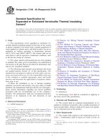
in areas subjected to weathering indices of 50 or greater and lot
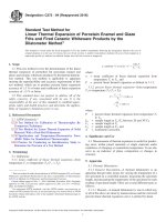
tags or certification that the lot of tile has passed the freezethaw testing accompanies the lot. See Fig. 1 for weathering
indices map.
7.3.3 Tile not tested for freeze-thaw shall state clearly that
the lot has not been tested for freeze-thaw acceptance on all lot
tags or certification.
7.3.4 Modify Test Methods C67 procedure for freezing and
thawing as follows:
7.3.4.1 The test specimens shall consist of five whole tile.
7.3.4.2 The freezing trays and containers shall be of sufficient size and depth to allow the tiles to be completely
submerged in water when placed horizontally.
7.4 Transverse Strength:
7.4.1 Apparatus—The transverse breaking strength of tiles
shall be determined as described in the Modulus of Rupture
(Flexural Test) in Test Methods C67 except as modified in 7.4.2
– 7.4.9.
7.4.2 Five tiles shall be tested wet after a 24-h submersion
in water at a temperature of 75 6 10°F (24 6 6°C) or five tiles
shall be tested dry after heating in a ventilated oven for 24 h at
a temperature of 230 to 239°F (100 to 115°C).
7.4.3 Tiles shall be considered to comply with this specification if they comply with either the wet or dry transverse
strength required. The choice of method, wet or dry, shall be
mutually agreed upon between specifier and supplier.
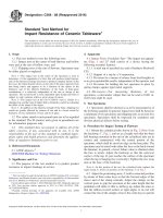
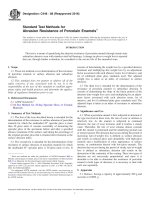
7.4.4 The span for the test shall be 12 in. (30.5 cm) 65 % or
2⁄3 the length of the tile, whichever is greater. The span is
measured between the centers of the lower support members
(see Fig. 2).
FIG. 1 Weathering Indices in the United States
3
C1492 − 03 (2016)
FIG. 2 Schematic of Assembly for Flexure Strength Testing
shall be placed between the faces of the support and loading
members and the surface of the tile.
7.4.4.1 It is permitted to use a shorter span than required by
7.4.4 when the length of the tile to be tested, or the installed
unsupported span of the tile, is not sufficient to allow a 12 in.
(30.5 cm) span to be used. In that case a shorter span, not less
than 2⁄3 of the length of the tile, or the total length of the longest
unsupported span as installed, whichever is less, shall be used.
7.4.5 The tile shall be tested in a three-point bending mode
in a horizontal plane with the bottom surface of the tile resting
on two lower support members and with the load being applied
to the upper (exposed) surface of the tile by a third member
moving in a direction perpendicular to the plane of the tile and
at mid-span (that is, equidistant from each of the lower support
members). A schematic of the assembly for testing a typical
“S” tile is shown in Fig. 2.
7.4.5.1 The two support members and the loading member
shall each be of metal or hardwood with 1 in. (25 mm) 6 5 %
wide faces. The faces shall be shaped (see Note 4) to closely
conform to the profile of the surface of the tile upon which they
bear during the test (the profile can, therefore, be different for
each member depending on the profile and cross-sectional
shape of the tile). The total height of the support members shall
not be more than 1 in. (25 mm) greater than the rise of the
profile. If hardwood, they should be backed up with steel
bearing plates at least 1⁄2 in. (13 mm) thick. A rubber shim strip
3⁄16 in. (4.8 mm) 6 10 % thick of hardness no greater than
shore durometer 30 (A scale), and 1 in. (25 mm) 6 5 % wide,
NOTE 4—The intent of the defined loading system is (1) to apply the
bending force with a loading member that pushes against as much of the
profiled surface of the tile as practical, (2) to support the tile on members
that support as much of the profiled surface of the tile as is practical, and
(3) to ensure that the contact area of both the loading and support members
is equally distributed on either side of the tile’s centerline in the long
direction to avoid nonsymmetrical loading.
For tile with complex profiles and cross sections but with flat bearing
surfaces that are at least 50 % of the width of the tile and that are also
equally distributed on either side of the length centerline, use flat support
and loading members to perform this test, provided that they otherwise
comply with the requirements of 7.4.4.1 – 7.4.5.1. When sufficient flat
bearing surfaces do not exist, use wood blocks of appropriate thickness
and profile and 1 in. (25 mm) wide to provide a surface that will permit
load application using a flat loading member that otherwise meets the
requirements of 7.4.4.1 – 7.4.5.1, and causes the load to be applied to at
least 50 % of the width of the tile and equally distributed on either side of
the length centerline of the tile.
Each wood block used that is to provide sufficient flat surface to allow
loading and supporting with the flat bearing members shall have a length
of at least 25 % of the width of the tile. Such blocks shall be spaced no
farther apart than 25 % of the width of the tile to avoid concentrated
loading. Loading support members shall be parallel to each other and be
placed in the same alignment across the width of the tile, when viewed
from the end of the tile, to avoid torsional loading.
7.4.5.2 The length of the support and loading members shall
not be less than the width of the tile.
4
C1492 − 03 (2016)
7.4.5.3 Both of the support members and the loading member shall be free to rotate in the longitudinal and transverse
directions of the test specimen and be adjusted so that they will
exert no negligible force in these directions. It is permitted to
accomplish this by spherically seated steel balls with appropriate supporting springs.
7.4.6 The tile shall be loaded uniformly and continuously,
without shock, at the rate not to exceed 1000 lbf (4448 N/min)
until fracture.
7.4.7 Record the load in pounds (kilograms) at the fracture
of the five tiles and report the average of the five tests and the
minimum individual result.
7.4.8 For a tile with a width greater than 14 in. (35.6 cm),
the minimum values in Table 3 are to be adjusted proportionally to the change in width according to Eq 1.
Transverse Break strength 5
Q ~ L/min! 5 1.25 3 A
where:
A = actual roof test area in square metres.
7.5.2.5 The flow rate for the diluge pipe shall be twice that
calculated for the spray unit above.
7.5.2.6 The flow rate shall be monitored by means of a
flowmeter.
7.5.2.7 The flow of water shall be maintained for a time
period of 2 h.
7.5.3 Acceptance Criteria—The tile shall be considered to
have passed the test if after 2 h:
7.5.3.1 Free water has not formed on the underside of the
tile, and
7.5.3.2 Not more than 25 % of the visible underside of any
one tile shall show dampness.
7.5.3.3 Example Calculation—If a test apparatus provides a
tile roof area of 4 by 4 ft, then you will have 16 ft2 of roof deck.
Flow Q = 0.031 × 16 ft2 = 0.50 gal/min for the spray unit. The
diluge unit is twice the spray unit and would therefore have a
flow of 1.0 gal/min. The combined flow would be a total of 1.5
gal/min on the tile roof.
Width ~ in.!
3 ~ Value in Table 3! (1)
14
7.4.9 The minimum values required shall be those listed in
Table 3.
7.5 Permeability:
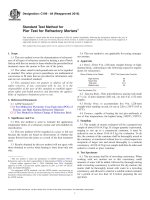
7.5.1 Apparatus—Construct a 3 ft (1 m) by 3 ft (1 m) frame,
as shown in Fig. 3, at a pitch not to exceed 30° 6 1° without
nails or roofing felt. Provide access to the underside of the roof
for observation. Provide illumination to the underside of the
tile, if required, to identify the presence of free water on the
underside of the tile.
7.5.1.1 Install the tiles as would be installed during field
application for tile headlap without the use of nails.
7.5.1.2 Place a 1⁄2 in. diluge pipe (12 mm) inside diameter
with 1⁄16 in. (2 mm) holes on 11⁄2 in. (38 mm) over the top
course of the roof to simulate run down from the higher course
(see Fig. 3). Place a spray nozzle over the center of the tile to
simulate direct rainfall and such that every tile on the roof will
receive an equal volume of water. The application of water
shall be such that a minimum volume is lost from overspray.
Water shall be maintained at 75 6 5°F (24 6 3°C).
7.5.2 Test Procedure—The simulated rainfall shall be applied to the roof deck at the following combined rates:
7.5.2.1 Via Diluge Pipe—6 in. (150 mm)/h.
7.5.2.2 Via Spray Nozzle—3 in. (75 mm)/h.
7.5.2.3 Total simulated rainfall shall be 9 in. (225 mm)/h.
7.5.2.4 Calculate the flow rates required for the spray unit to
achieve the simulated rainfall for a given roof area by Eq 2.
Q ~ gal/min! 5 0.031 3 A
7.6 Water Absorption:
7.6.1 Apparatus and Procedure—The procedures and apparatus should be in accordance with the section on absorption in
Test Methods C140.
7.6.2 The tile shall then be classified according to Table 4.
7.6.3 The maximum percent water absorption (average of 5
units) and individual specimen maximum, shall be as listed in
Table 5.
8. Texture and Color
8.1 The texture and color of tiles should be specified by the
purchaser and mutually agreed upon between purchaser and
supplier with reference to a sample of the type specified
representing the possible range of textures and shades of color.
9. Inspection
9.1 Inspection of the material covered by this specification
shall be agreed upon between the purchaser and the supplier as
part of the purchase contract.
9.2 The tile, as delivered to the site, shall by visual
inspection conform to the requirements specified by the purchaser or to the sample or samples approved as the standard of
comparison and to the samples passing the tests for physical
requirements. Minor indentations, chips, or surface crazing
incidental to the usual method of manufacture, shall not be
deemed grounds for rejection.
(2)
where:
A = actual roof test area in square feet.
Metric Equivalent:
9.3 After tile are placed in use, the manufacturer or manufacturer’s shall not be held responsible for compliance of the
tile with the requirements of this specification for color or
damage caused during installation.
TABLE 3 Transverse Breaking Strength, min, Lbf (N)
Dry
High Profile
Medium
Profile
Low Profile
Wet
Average of
5 Tile
Individual
Tile
Average of
5 Tile
Individual
Tile
400 (1779)
300 (1334)
350 (1556)
250 (1112)
300 (1334)
225 (1001)
260 (1157)
200 (890)
300 (1334)
250 (1112)
225 (1001)
200 (890)
10. Rejection and Rehearing
10.1 When material that fails to conform to the requirements of this specification is rejected, such rejection shall be
promptly reported in writing to the supplier. In case of
5
C1492 − 03 (2016)
FIG. 3 Diluge Pipe
TABLE 4 Weight Classification
Weight Classification
Oven Dry Weight of Tile (lb/ft3)
Normal
Medium
Lightweight
Greater than 125
105 to 125
Less than 105
conforming to the specified requirements, provided this is done
within 20 days after receipt of notice of the specific cause of
rejection.
10.2 When the shipment fails to conform to the requirements for the grade and type specified, the manufacturer is not
prohibited from sorting the lot, and when sorted new specimens shall be selected by the purchaser from the retained lot
and tested at the expense of the supplier. When the second set
of specimens fails to meet the requirements, the entire lot shall
be rejected.
TABLE 5 Water Absorption
Weight Classification
Normal
Medium
Lightweight
Max % Absorption,
Average of Five Tiles
Max % Absorption,
Individual Tile
10.5 %
14.5 %
18.0 %
12.5 %
16.5 %
20.0 %
11. Certification
11.1 When specified in the purchase order or contract, the
purchaser shall be furnished certification that a representative
sample of each lot has been either tested or inspected as
required by this specification and the requirements have been
rejection, when not specifically excluded in the purchase
contract, the supplier shall have the right to inspect the rejected
lot and resubmit the lot after removal of the material not
6
C1492 − 03 (2016)
met. When specified in the purchase order or contract, a report
of the test results shall be furnished.
12. Keywords
12.1 absorption; concrete; concrete roof tile; durability;
freeze thaw durability; permeability; roof; roofing; tile; transverse breaking strength
NOTE 5—Unless otherwise specified in the purchase contract, the cost
of the tests is typically borne as follows: If the results of the test show that
the tile do not conform to the requirements of this specifications, the cost
is typically borne by the seller. If the results of the test show that the tile
do conform to the requirements of this specification, the cost is typically
borne by the purchaser.
ANNEX
(Mandatory Information)
A1. EXPLANATORY INFORMATION
A1.3 Winter Rainfall—the sum, in inches (millimetres), of
the mean monthly corrected precipitation (rainfall) occurring
during the period between and including the normal date of the
first killing frost in the fall and the normal date of the last
killing frost in the spring. The winter rainfall for any period is
equal to the total precipitation less one tenth of the total fall of
snow, sleet, and hail. Rainfall for a portion of a month is
prorated.
A1.1 The effect of weathering on tile is related to the
weathering index, which for any locality is the product of the
average annual number of freezing cycle days and the average
annual winter rainfall in inches (millimetres), defined as
follows.3
A1.2 Freezing Cycle Day—any day during which the air
temperature passes either above or below 32°F (0°C). The
average number of freezing cycle days in a year may be taken
to equal the difference between the mean number of days
during which the minimum temperature was 32°F or below,
and the mean number of days during which the maximum
temperature was 32°F or below.
A1.4 Fig. 1 indicates general areas of the United States
which correspond to the weathering index categories. The
index for geographic locations near the 50 line should be
determined by analysis of weather bureau local climatological
summaries, with due regard to the effect of microclimatic
conditions, especially altitude.
3
Data needed to determine the weathering for any locality may be found or
estimated from tables of Local Climatological Data – Annual Summary with
Comparative Data available from the National Oceanic and Atmospheric Administration.
ASTM International takes no position respecting the validity of any patent rights asserted in connection with any item mentioned
in this standard. Users of this standard are expressly advised that determination of the validity of any such patent rights, and the risk
of infringement of such rights, are entirely their own responsibility.
This standard is subject to revision at any time by the responsible technical committee and must be reviewed every five years and
if not revised, either reapproved or withdrawn. Your comments are invited either for revision of this standard or for additional standards
and should be addressed to ASTM International Headquarters. Your comments will receive careful consideration at a meeting of the
responsible technical committee, which you may attend. If you feel that your comments have not received a fair hearing you should
make your views known to the ASTM Committee on Standards, at the address shown below.
This standard is copyrighted by ASTM International, 100 Barr Harbor Drive, PO Box C700, West Conshohocken, PA 19428-2959,
United States. Individual reprints (single or multiple copies) of this standard may be obtained by contacting ASTM at the above
address or at 610-832-9585 (phone), 610-832-9555 (fax), or (e-mail); or through the ASTM website
(www.astm.org). Permission rights to photocopy the standard may also be secured from the Copyright Clearance Center, 222
Rosewood Drive, Danvers, MA 01923, Tel: (978) 646-2600; />
7