Astm d 178 01 (2010)
Bạn đang xem bản rút gọn của tài liệu. Xem và tải ngay bản đầy đủ của tài liệu tại đây (224.68 KB, 9 trang )
Designation: D178 − 01 (Reapproved 2010)
Standard Specification for
Rubber Insulating Matting1
This standard is issued under the fixed designation D178; the number immediately following the designation indicates the year of
original adoption or, in the case of revision, the year of last revision. A number in parentheses indicates the year of last reapproval. A
superscript epsilon (´) indicates an editorial change since the last revision or reapproval.
This standard has been approved for use by agencies of the U.S. Department of Defense.
Cracking (Withdrawn 2007)3
D570 Test Method for Water Absorption of Plastics
D573 Test Method for Rubber—Deterioration in an Air
Oven
D1692 Method of Test for Rate of Burning or Extent and
Time of Burning of Cellular Plastics Using a Specimen
Supported by a Horizontal Screen (Withdrawn 1976)3
2.2 American National Standard:4
ANSI C84.1 Voltage Ratings for Electric Power Systems and
Equipment (60 Hz)
1. Scope
1.1 This specification covers acceptance testing of rubber
insulating matting for use as a floor covering for protection of
workers.
1.2 Two types of matting, differing in chemical and physical
characteristics, are provided and are designated as Type I and
Type II matting.
1.3 The following safety hazards caveat applies only to the
test method portion, Sections 17 to 19, of this specification:
This standard does not purport to address all of the safety
concerns, if any, associated with its use. It is the responsibility
of the user of this standard to establish appropriate safety and
health practices and determine the applicability of regulatory
limitations prior to use.
3. Terminology
3.1 Definitions:
3.1.1 user, n—as used in 4.3.1, the entity employing the
actual worker(s) utilizing the equipment; if no separate
employer, then the individual.
3.1.2 voltage, maximum retest, n—voltage, either ac rms or
dc avg, which is equal to the proof-test voltage for new
protective equipment.
3.1.3 voltage, retest, n—voltage, either ac rms or dc avg,
that used protective equipment must be capable of withstanding for a specified test period without breakdown.
3.1.4 voltage, nominal design, n—a nominal value consistent with the latest revision of ANSI C84.1, assigned to the
circuit or system for the purpose of conveniently designating
its voltage class.
NOTE 1—Rubber insulating matting should remain flexible for use
through normal temperature ranges.
NOTE 2—Rubber as used in this specification is a generic term that
includes elastomers and elastomer compounds, regardless of origin.
2. Referenced Documents
2.1 ASTM Standards:2
D149 Test Method for Dielectric Breakdown Voltage and
Dielectric Strength of Solid Electrical Insulating Materials
at Commercial Power Frequencies
D297 Test Methods for Rubber Products—Chemical Analysis
D412 Test Methods for Vulcanized Rubber and Thermoplastic Elastomers—Tension
D471 Test Method for Rubber Property—Effect of Liquids
D518 Test Method for Rubber Deterioration—Surface
3.1.5 voltage, maximum use, n—the ac voltage (rms) classification of the protective equipment that designates the
maximum nominal design voltage of the energized system that
may be safely worked. The nominal design voltage is equal to
phase-to-phase voltage on multiphase circuits.
3.1.5.1 If there is no multiphase exposure in a system area,
and the voltage exposure is limited to phase (polarity on dc
systems) to ground potential, the phase (polarity on dc systems) to ground potential shall be considered to be the nominal
design voltage.
1
This specification is under the jurisdiction of ASTM Committee F18 on
Electrical Protective Equipment for Workers and is the direct responsibility of
Subcommittee F18.25 on Insulating Cover-Up Equipment. This standard replaces
ANSI Standard J 6.7, which is no longer available.
Current edition approved Oct. 1, 2010. Published November 2010. Originally
approved in 1923. Last previous edition approved in 2005 as D178 – 01(2005).
DOI: 10.1520/D0178-01R10.
2
For referenced ASTM standards, visit the ASTM website, www.astm.org, or
contact ASTM Customer Service at For Annual Book of ASTM
Standards volume information, refer to the standard’s Document Summary page on
the ASTM website.
3
The last approved version of this historical standard is referenced on
www.astm.org.
4
Available from American National Standards Institute, 11 West 42nd Street,
13th Floor, New York, NY 10036.
Copyright © ASTM International, 100 Barr Harbor Drive, PO Box C700, West Conshohocken, PA 19428-2959. United States
1
D178 − 01 (2010)
5.1.2 Type II, made of any elastomer or combination of
elastomeric compounds with one or more of the following
special properties:
5.1.2.1 A—Ozone resistance
5.1.2.2 B—Flame resistance
5.1.2.3 C—Oil resistance
5.1.3 The class designation shall be based on the electrical
properties as shown in Table 2.
3.1.5.2 If electrical equipment and devices are insulated, or
isolated, or both, such that the multiphase exposure on a
grounded wye circuit is removed, then the nominal design
voltage may be considered as the phase-to-ground voltage on
that circuit.
4. Significance and Use
4.1 This specification covers the minimum electrical,
chemical, and physical properties guaranteed by the manufacturer and the detailed procedures by which such properties are
to be determined. The purchaser may at his option perform or
have performed any of these tests in order to verify the
guarantee. Claims for failure to meet the specification are
subject to verification by the manufacturer.
6. Ordering Information
6.1 Orders for matting under this specification should include the following information:
6.1.1 Type,
6.1.2 Class,
6.1.3 Thickness,
6.1.4 Width,
6.1.5 Length, and
6.1.6 Color.
4.2 Rubber insulating matting is used for personal protection; therefore when authorizing its use a margin of safety
should be allowed between the maximum voltage at which it is
used and the proof-test voltage at which it is tested. The
relationship between proof-test and the maximum voltage at
which matting shall be used is shown in Table 1.
6.2 The listing of types, classes, thicknesses, widths,
lengths, and colors is not intended to mean that all shall
necessarily be available from manufacturers; it signifies only
that, if made, they shall conform to the details of this
specification.
4.3 Work practices vary from user to user, depending upon
many factors. These may include, but are not limited to,
operating system voltages, construction design, work procedures and techniques, weather conditions etc. Therefore, except for the restrictions set forth in this specification because of
design limitations, the use and maintenance of this equipment
is beyond the scope of this specification
4.3.1 It is common practice and the responsibility of the user
of this type of protective equipment to prepare complete
instructions and regulations to govern the correct and safe use
of such equipment.
7. Manufacture and Marking
7.1 The matting shall consist of a rubber compound with a
smooth, corrugated, or diamond design on one surface and may
be backed with fabric, or may have one or more fabric inserts.
The back of the matting may be finished with cloth imprint or
other slip-resistant material. Any such fabric insert shall not
affect adversely the dielectric characteristics of the matting.
7.2 Each piece of matting shall be marked clearly and
permanently at a maximum interval of 1 m (3 ft) with the name
of the manufacturer or supplier, ASTM D178, type, and class.
5. Classification
5.1 Matting covered under this specification shall be designated as Type I or Type II; Class 0, Class 1, Class 2, Class 3,
or Class 4.
5.1.1 Type I, made of any elastomer or combination of
elastomer compounds, properly vulcanized.
8. Dimensions and Permissible Variations
8.1 Width—Standard widths shall be 610 6 13 mm (24.0 6
0.5 in.), 760 6 13 mm (30.0 6 0.5 in.), 914 6 25 mm (36 6
1 in.) and 12206 25 mm (48 6 1 in.).
8.2 Thickness—The thickness of the matting shall be as
specified in Table 3. Measurements shall be made over the
corrugations or diamonds. The corrugations shall be not more
than 3.2 mm (0.125 in.) deep. The diamonds shall not be higher
than 1.6 mm (0.062 in.).
TABLE 1 Proof Test/Use Voltage Relationship
NOTE 1—The ac voltage (rms) classification of the protective equipment designates the maximum nominal design voltage of the energized
system that may be safely worked. The nominal design voltage is equal to:
a. The phase to phase on multiphase circuits or
b. The phase to ground voltage on single phase grounded circuits.
Nominal Maximum
Class of InsulatUse Voltage A
Phase-Phase
ing Matting
ac rms, max
0
1
2
3
4
1
7
17
26
36
000
500
000
500
000
AC Proof-Test
Voltage, rms V
5
10
20
30
40
000
000
000
000
000
9. Workmanship and Finish
9.1 The matting shall be free of harmful physical
irregularities, which can be detected by thorough test or
inspection.
9.1.1 Nonharmful Irregularities—Surface irregularities may
be present on all rubber matting due to imperfections in molds
and inherent difficulties in the manufacturing processes. These
irregularities may appear as indentations, protuberances, or
imbedded foreign material that are acceptable provided that:
9.1.1.1 The indentation or protuberance tends to blend into
a smooth slope upon stretching of the material.
9.1.1.2 The rubber thickness at any irregularity conforms to
the thickness requirements.
DC Proof-Test
Voltage, avg, V
20
40
50
60
70
000
000
000
000
000
A
Except for Class O equipment, the maximum use voltage is based on the
following formula:
Maximum use voltage (maximum nominal design voltage) 0.95 ac proof-test
voltage − 2000
2
D178 − 01 (2010)
TABLE 2 Electrical Test Requirements
DCA
AC
Class
0
1
2
3
4
Electrode Clearances, min B
mm
in.
76
76
127
178
178
3
3
5
7
10
Proof Test
Voltage
Dielectric Test Voltage
rms V
rms V
5
10
20
30
40
000
000
000
000
000
6
20
30
40
50
000
000
000
000
000
Electrode Clearances, min B
mm
in.
76
76
152
203
305
3
3
6
8
12
Proof Test
Voltage
avg V
20
40
50
60
70
000
000
000
000
000
Dielectric Test
Voltage
avg V
35
60
70
80
90
000
000
000
000
000
A
DC proof-test, voltages were determined using negative polarity.
These nominal clearances are intended to avoid flashover and may be increased by no more than 2 in. (51 mm) when required by change in atmospheric conditions from
the standard of 100 kPa (1 atm) barometric pressure and average humidity conditions. These clearances may be decreased if atmospheric conditions permit.
B
TABLE 3 Thickness Measurements
Class
0
1
2
3
4
Thickness
11.3 The Type IIA matting material shall show no visible
effects from ozone when tested in accordance with 18.6.1, or
18.6.2. In case of dispute, Method A of the ozone resistance test
shall be the referee test.
Tolerance
mm
in.
mm
in.
3.2
4.8
6.4
9.5
12.7
0.13
0.19
0.25
0.38
0.50
0.8
0.8
0.8
1.2
1.2
0.03
0.03
0.03
0.05
0.05
12. Guarantee
12.1 The manufacturer or supplier shall replace, without
charge to the purchaser, unused matting which, at any time
within a period of nine (9) months from date of initial delivery
of shipment to the purchaser or his designee, fail to pass the
tests in this specification. This guarantee will be binding on the
manufacturer or supplier only if the matting has been properly
stored and has not been subjected to more than an original
acceptance test and one retest.
9.1.1.3 Foreign material remains in place when the matting
is bent and stretches equally with the material surrounding it.
10. Chemical and Physical Requirements
10.1 Insulating matting shall conform to the physical requirements in Table 4. For Type II matting, flame or oil
resistance can be determined by conducting the tests in 19.2.5
or 19.2.6, respectively.
12.2 Any acceptance test made by the purchaser, or the
purchaser’s designee, shall be performed within the first two
(2) months of the guarantee period unless otherwise specified.
NOTE 3—Proper storage means that the matting is stored without
distortion, and not stored directly above or in proximity to steam pipes,
radiators, or other sources of artificial heat, or exposed to direct sunlight
or sources of ozone. It is desirable that the ambient storage temperature
shall not exceed 35°C (95°F).
11. Electrical Requirements
11.1 The entire length of each roll of matting when new
(unused) shall withstand the 60-Hz ac proof-test voltage (rms
value) or the dc proof-test voltage (average value) specified in
Table 2. The test voltage shall be applied continuously for 1
min.
13. Sampling
13.1 Each roll of matting in a lot or shipment shall be
subject to inspection and test by the manufacturer including
electrical proof test to levels required in Table 2 of this
specification.
11.2 The matting material when tested between 50-mm
(2-in.) disk electrodes with edges rounded to a radius of 6 mm
(0.25 in.), shall show a 60-Hz dielectric strength of not less
than the requirements shown in Table 2 for the thickness of
each individual specimen.
13.2 An original sample of sufficient material shall be cut
from the end of a roll or rolls selected from the lot for the test
requirements of Section 10, 11.2, and 11.3. A lot is defined as
that quantity of material produced by a common manufacturing
process during a consecutive time period not to exceed 24 h. If
failure occurs in the first sample, a second sample of the same
quantity shall be selected and tested.
TABLE 4 Physical Requirements
Tensile strength, min, MPa (psi)
Tension set, max, at 150 % elongation,
51-mm (2-in.) bench mark, mm (in.)
Elongation, min, %
Moisture absorption, max in-crease A ,
%
Flame resistance, Type IIB
Oil resistance, max, volume increase,
Type IIC B
Type I
4.83 (700)
12.7 (0.50)
Type II
4.83 (700)
12.7 (0.50)
250
1 1⁄2
250
3
not applicable
12.7 mm (0.5 in.)
after 30 s
4
not applicable
14. Rejection
14.1 Individual rolls shall be rejected if they fail to meet the
manufacturing and marking requirements of Section 7, the
electrical requirements of 11.1, the width requirements of 8.1,
the minimum thickness requirements of 8.2, or the workmanship requirements of Section 9.
A
Distilled water—23°C (75°F).
ASTM Oil No. 2 room temperature for 24 h.
14.2 The entire lot or shipment of matting shall be rejected
under any of the following conditions:
B
3
D178 − 01 (2010)
TEST METHODS
14.2.1 If 5 % or more, but not less than two rolls of the
matting, in a shipment fail to meet the requirements of 11.1.
14.2.2 If two dielectric breakdowns that do not meet the
dielectric strength value specified in 11.2 occur in five tests on
the specimen.
14.2.3 If one dielectric breakdown of five tests on the
original and one or more dielectric breakdowns of five tests on
an additional specimen fail to meet the dielectric strength value
specified in 11.2.
14.2.4 If the sample specimens of Type IIA matting, using
the sampling methods and criteria specified in 18.6.1 or 18.6.2,
fail to meet the ozone resistance requirements of 11.3.
14.2.5 If the sample specimens of Type IIB matting using
the sampling methods and criteria specified in 19.2.5, fail to
meet the flame-resistant requirements of 10.1.
14.2.6 If the sample specimens of Type IIC matting using
the sampling methods and criteria specified in 19.2.6 fail to
meet the oil resistance requirements of 10.1.
17. Sequence of Testing
17.1 The following order of procedure is suggested for
testing rubber insulating matting.
17.1.1 Inspection of the surfaces in accordance with Section
9.
17.1.2 The dimensions in accordance with Sections 8 and
16.
17.1.3 Electrical proof test in accordance with the appropriate paragraphs of Section 18.
17.1.4 Breakdown voltage test in accordance with the appropriate paragraphs of Section 18.
17.1.5 Ozone resistance tests in accordance with the appropriate paragraphs of Section 18.
17.1.6 Chemical and physical property tests in accordance
with Section 19.
18. Electrical Tests
18.1 Conditioning—Prior to testing, the matting shall be
made in a flat position.
14.3 The testing shall be terminated and the manufacturer or
supplier notified if, during the course of testing, 5 % or more,
but not less than two rolls, of the matting in a lot or shipment,
fail to meet the requirements of 11.1, 11.2, or 11.3 as
determined by the rejection criteria of 14.1, 14.2, 14.2.1,
14.2.2, 14.2.3, 14.2.4, 14.2.5, or 14.2.6. The manufacturer or
supplier may in such a case require the purchaser to submit
proof that the test procedure and equipment conform to the
appropriate paragraphs of Section 18. When such proof has
been furnished, the manufacturer or supplier may request that
his representative witness the testing of additional rolls from
the shipment.
NOTE 4—Both ac and dc proof-test methods are included in this section.
It is intended that one method be selected for the electrical acceptance
tests. The method selected shall be at the option of the purchaser, and the
supplier should be so notified of the selection.
18.2 Warning—It is recommended that the test apparatus
be designed to afford the operator full protection in the
performance of his duties. Reliable means of de-energizing and
grounding the high-voltage circuit should be provided. It is
particularly important to incorporate a positive means of
grounding the high-voltage section of dc test apparatus due to
the likely presence of high-voltage capacitance charges at the
conclusion of the test.
14.4 The entire lot or shipment of matting may be rejected
at the option of the purchaser if two of the five specimens
tested fail any of the separate requirements outlined in Section
10.
18.3 AC Proof Test:
18.3.1 Electrodes—Where electrodes are to be employed as
part of the test apparatus, they shall be of such design so as to
apply the electrical stress uniformly over the test area without
producing corona at any point, or mechanical strain in the
material. The electrodes used in proof tests shall be of such
dimensions that the flashover clearances specified in Table 2
are not exceeded. A satisfactory procedure for ac proof testing
utilizes electrodes that will provide intimate contact without
undue pressure.
14.5 The entire lot or shipment of matting may be rejected
at the option of the purchaser if 25 % of the matting in the lot
or shipment fail to meet the requirements of Section 8 or 9.
14.6 All rejected material shall be returned unaltered except
as required for sampling, as directed by the manufacturer at his
or the supplier’s request. However, those mats punctured when
tested in accordance with 11.1 or 11.2 shall be stamped,
punched, or cut prior to being returned to the supplier to
indicate that they are unfit for electrical use.
NOTE 5—Rectangular metal sheets approximately 3 mm (0.06 in.)
thick, having smoothly rounded edges and corners, have been found to be
satisfactory for this purpose. Also satisfactory are wet felt or sponge-top
electrodes.
15. Packaging
18.3.2 Voltage Supply and Regulation:
18.3.2.1 The test equipment used in both the proof-test
voltage and dielectric breakdown voltage tests shall be capable
of supplying an essentially stepless and continuously variable
voltage to the test specimen. Motor-driven regulating equipment is convenient and tends to provide uniform rate-of-rise to
the test voltage. The test apparatus should be protected by an
automatic circuit-breaking device designed to open promptly
on the current produced by breakdown of a specimen under
test. This circuit breaking device should be designed to protect
the test equipment under any conditions of short circuit.
15.1 Matting shall be packaged either flat or in rolls and
shall not be distorted mechanically.
16. Thickness Measurements
16.1 Thickness measurements should be made on complete
matting samples with a caliper graduated to within 0.03 mm
(0.001 in.). At least five thickness measurements shall be made
at selected points uniformly distributed over the test area of the
matting.
4
D178 − 01 (2010)
18.4.3 Procedure—The procedure shall be the same as the
ac proof test, except that the rate-of-rise shall be approximately
3000 V/s dc.
18.3.2.2 The desired test voltage may be obtained most
readily from a step-up transformer energized from a variable
low-voltage source. The transformer and its control equipment
shall be of such size and design that, with the test specimen in
the circuit, the crest factor (ratio of maximum to mean
effective) of the test voltage shall differ by not more than 5 %
from that of a sinusoidal wave over the upper half of the range
of test voltage.
18.3.2.3 The accuracy of the voltage-measuring circuit shall
be within 6 2 % of full scale. The correct rms value of the
actual sinusoidal voltage wave-form applied to the matting
may be measured by one of the following methods: (1) a
voltmeter used in conjunction with a calibrated instrument
transformer connected directly across the high-voltage circuit,
(2) a calibrated electrostatic voltmeter connected directly
across the high-voltage circuit, or (3) an ac meter connected in
series with appropriate high-voltage type resistors directly
across the high-voltage circuit.
18.3.2.4 The crest factor may be checked by the use of a
peak-reading voltmeter connected directly across the highvoltage circuit. If an electrostatic voltmeter or an rms voltmeter
in conjunction with an instrument potential transformer is
connected across the high-voltage circuit, a standard sphere
gap may be sparked over and the corresponding voltage
compared with the reading of the rms voltmeter.
18.3.3 Test—The proof-test voltage shall be initially applied
at a low value and then gradually increased at a constant
rate-of-rise of approximately 1000 V/s ac until the prescribed
test voltage level is reached, or failure occurs. The test period
starts at the instant that the prescribed testing voltage is
reached. Reduce the applied voltage to at least half value,
unless an electrical puncture has already occurred, at the end of
the test period before opening the test circuit.
18.5 Dielectric Breakdown Test—The dielectric breakdown
test shall be performed in accordance with Test Method D149.
The voltage should be applied at the rate of 3000 V/s under the
short-time procedure. The specimen shall be representative of
the matting material to be tested. Sufficient material shall be
available to permit making five tests.
18.6 Ozone Resistance Test—The ozone resistance test shall
be made in accordance with one of the following methods to
ensure conformance of Type IIA matting with the requirements
of 11.3:
18.6.1 Method A—The ozone resistance test shall be made
in accordance with Procedure A of Test Method D518. Cut the
specimen to a 10 by 100-mm (0.5 by 4-in.) rectangular size. A
temperature of 40°C (104°F) shall be maintained. Procedure A
shall be followed using a 20 % extension. The ozone concentration shall be maintained at 500 6 50 mm3/m3 (50 6 5
pphm) by volume for a 3-h test period. Type II matting shall
show no effect from ozone exposure during this test period.
18.6.2 Method B—The ozone resistance test shall be made
on a 100 by 150-mm (4 by 6-in.) specimen of the matting
material prepared from a sample suitably conditioned by lying
flat for 24 h. The specimen should be draped over a 25-mm
(1-in.) diameter metal tube of sufficient length to completely
underlie the specimen, while possessing additional length for
the required mounting support. The metal tubing is electrically
grounded. The free ends of the specimen shall be clamped
beneath the tubing electrode so that an intimate contact is
established between the specimen and the tubing along the
upper half of the cylindrically-shaped electrode surface. A
piece of flat aluminum sheet foil, approximately 50 by 100 mm
(2 by 4 in.), shall be placed over the draped specimen so as to
provide adequate separation distance to prevent flashover
between the foil and the metal tubing. An electrode wire shall
be connected to the aluminum foil.
18.6.2.1 The outer electrode (metal foil) shall be energized
to approximately 15 kV ac (rms) from a stable 60-Hz source.
The 15 kV potential may be derived from a suitably rated
potential transformer energized from its low-voltage winding
through a continuously variable autotransformer. An overcurrent protective device should be incorporated into the lowvoltage control circuit in case of an electrical breakdown.
18.6.2.2 The ozone resistance of the specimen should be
determined qualitatively, by inspection, after a 1-h exposure
period in the test apparatus at the 15 kV potential. Any visible
signs of ozone deterioration of the matting material such as
checking, cracking, breaks, pitting, etc., shall be considered as
evidence of failure to meet the requirements of Type IIA
matting. At least two specimens from each sample of matting
selected in accordance with 12.2 shall be tested. Two specimens should not be taken from the same section of the sample
matting.
18.4 DC Proof Test:
18.4.1 Electrodes—The dc proof-test may be made with dry
electrodes that consist of two flat metallic plates, at least one of
which is sized so that the flashover distances recommended in
Table 2 are not exceeded. The edges of these plates should be
rounded so as to eliminate sharp nicks and protuberances.
18.4.2 Voltage Supply and Regulation:
18.4.2.1 The dc proof-test voltage shall be obtained from a
dc source capable of supplying the required voltage. The
peak-to-peak ac ripple component of the dc proof-test voltage
shall not exceed 2 % of the average voltage value under
no-load conditions.
18.4.2.2 The dc proof-test voltage shall be measured by a
method that provides the average value of the voltage applied
to the matting. It is recommended that the voltage be measured
by the use of a dc meter connected in series with appropriate
high-voltage type resistors across the high-voltage circuit. An
electrostatic voltmeter of proper range may be used in place of
the dc meter-resistor combination. The accuracy of the voltage
measuring circuit shall be within 62 % of full scale.
NOTE 6—The rate of ozone degradation by use of Method B is inversely
5
D178 − 01 (2010)
19.2.3 The moisture absorption tests shall be performed in
accordance with Test Method D570, using the 24-h immersion
procedure at a temperature of 23°C (75°F).
19.2.4 The accelerated aging tests shall be performed in
accordance with Test Method D573. After being subjected to a
temperature of 70 6 1°C (158 6 2°F) in circulating air for 7
days, the tensile strength of the specimen shall not be less than
50 % of the original.
19.2.5 The flame resistance tests called for in Type IIB shall
be performed in accordance with Test Method D1692, with the
maximum limits conforming to the requirements of classification SE (Self-Extinguishing).
19.2.6 The oil resistance tests called for in Type IIC shall be
performed in accordance with Test Method D471.
proportional to the relative humidity of the surrounding air. Empirical data
indicate, however, that visible ozone effects will be evident over a broad
range of ambient humidities under these test conditions.
19. Chemical and Physical Tests
19.1 Chemical Tests—The composition of the rubber hydrocarbon portion of Type I matting may be determined using the
test methods in Test Methods D297, or the manufacturer’s
formulation processes may be certified by appropriate personnel.
19.2 Physical Tests:
19.2.1 Physical tests should be performed to determine the
physical requirements specified in Section 8. The matting
samples should be conditioned by storing in a flat position for
24 h at room temperature.
19.2.2 The tensile strength, elongation, and tension set tests
shall be performed in accordance with Test Methods D412. The
tensile strength and elongation specimens shall conform in
dimensions to Die C. The tensile set specimens shall conform
to Die B. The elongation in the tensile set shall be as specified
in Table 4.
20. Precision and Bias
20.1 No statement is made about either the precision or the
bias of the test methods in this standard for measuring the
dielectric strength since the results merely state whether there
is conformance to the criteria for success specified in the
procedure.
APPENDIX
(Nonmandatory Information)
X1. TEST METHOD FOR RATE, EXTENT, OR TIME, OR A COMBINATION THEREOF, OF BURNING OF CELLULAR
PLASTICS USING A SPECIMEN SUPPORTED BY A HORIZONTAL SCREEN
X1.2. Referenced Documents
X1.1. Scope
X1.1.1 This test method covers a small-scale horizontal
laboratory screening procedure for measuring the rate, extent,
or time, or a combination thereof, of burning of rigid or flexible
cellular plastics in accordance with this test procedure.
X1.2.1 ASTM Standards:2
D1564 Testing Flexible Cellular Materials—Slab Urethane
Foam; Replaced by D 3574 (Withdrawn 1978)4
D1565 Specification for Flexible Cellular Materials—Vinyl
Chloride Polymers and Copolymers (Open-Cell Foam)3
D2406 Methods of Testing Flexible Cellular MaterialsMolded Urethane Foam; Replaced by D 3574 (Withdrawn
1979)4
D3014 Test Method for Flame Height, Time of Burning, and
Loss of Mass of Rigid Thermoset Cellular Plastics in a
Vertical Position
X1.1.2 Materials that exhibit pronounced shrinking, curling,
or melting away upon heating cannot be evaluated by this test
method.
X1.1.3 This test method is not applicable to materials that
cannot be ignited under the conditions of this test, or to
materials that exhibit progressive combustion without flame
(continued glowing or charring).
NOTE X1.1—The rate of burning or extent of burning of rigid cellular
plastics also may be determined by Test Method D3014 where the
specimen is supported vertically.
X1.3. Significance and Use
X1.3.1 Tests made on a cellular plastic under conditions
herein prescribed can be of considerable value in comparing
the rate of burning and/or extent and time of burning of
different materials, in controlling manufacturing processes, or
as a measure of deterioration or change in burning characteristics prior to or during use.
X1.1.3.1 Warning—During the course of combustion,
gases or vapors, are evolved that may be hazardous to
personnel. Adequate precautions should be taken to protect the
operator.
X1.1.4 This standard does not purport to address all of the
safety concerns, if any, associated with its use. It is the
responsibility of the user of this standard to establish appropriate safety and health practices and determine the applicability of regulatory limitations prior to use.
X1.3.2 This test method is not intended to be a criterion for
fire hazard. The fire hazard created by materials depends upon
the form and end use of the material. Assessment of fire hazard
includes, but is not limited to, many factors, such as, ease of
6
D178 − 01 (2010)
ignition, burning rate, flame spread, fuel contribution, intensity
of burning, and products of combustion.
X1.4. Apparatus
X1.4.1 Test Chamber—Any enclosure is satisfactory that is
large enough to provide quiet, draft-free air surrounding the
specimen during the test, yet will permit normal thermal
circulation of air past the specimen during burning. A hood is
recommended in order to remove the sometimes noxious
products of combustion. If a test chamber is used. It should be
of such a design that it can be used in a hood. For referee
purposes, test results with the chamber should be the same
whether or not the hood exhaust is on. In cases of discrepancy,
values obtained with the damper closed or the hood fan off, or
both, will be considered valid.
X1.4.1.1 The recommended test chamber should be constructed of sheet metal or other fire-resistant material, having
inside dimensions 300 mm wide, 600 mm long, and 760 mm
high, open at the top, with a ventilating opening approximately
25 mm high around the bottom. A viewing window of
heat-resistant glass should be of sufficient size and in such a
position that the entire length of the specimen under test may
be observed. The chamber should be opened readily and closed
to facilitate mounting and ignition of the test specimen.
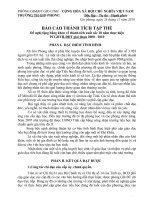
FIG. X1.1 Relative Position of Burner Wing Top, Specimen, and
Specimen Support
X1.4.2 Burner—A standard 9.5 6 0.5-mm outside diameter
barrel bunsen or Tirrill burner fitted with a 48 6 1-mm width
wing top.
NOTE X1.2—The wing top may have to be opened to approximately 3
6 0.1 mm to provide the flame required in X1.6.4.
X1.4.3 Fuel Supply—Propane gas of at least 85 % purity.
X1.4.4 Specimen Support—Wire cloth (wire screen)5
6.5-mm mesh using 0.8-mm diameter steel wire. The wire
cloth specimen support 75 by 215 mm shall have a 15 6 1 mm
of length bent to form a right angle. This will form the
specimen support as shown in Fig. X1.1 and Fig. X1.2.
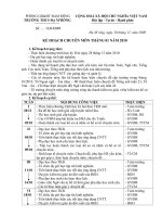
X1.4.5 Specimen Support Holders—Any holding device
that will clamp the wire cloth specimen support horizontally so
that the bottom of the bent-up portion is 13 6 1-mm above the
top of the burner wing top, as shown in Fig. X1.1. A typical
arrangement consists of two laboratory ring stands with two
adjustable flat-surface clamps, which may be locked in place
by set screw and lock nut. See Fig. X1.2 and Fig. X1.3.
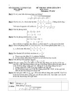
FIG. X1.2 Relative Position of Burner Wing Top, Flame,
Specimen, and Specimen Support
X1.4.6 Sheet of Flame-Resistant Material, 250 by 250 by
6.5 mm shall be placed on the bottom of the test chamber.
X1.4.7 Aluminum Foil.
X1.4.10 A device to ensure correct relative positioning of
burner and specimen.
X1.4.8 Timing Device, accurate to 6 1 s.
X1.5. Test Specimen
X1.4.9 Measuring Scale, graduated in at least 2.0-mm
intervals.
X1.5.1 Five specimens 50 6 0.25 mm wide by 1506 1 mm
long are needed.
X1.5.1.1 Specimens shall be cut from representative material. Materials supplied in thicknesses over 13 mm shall be cut
to 13 mm thickness. Materials formed in thicknesses of 13 mm
or less shall be tested at the thickness supplied.
X1.5.1.2 Materials with directional effects such as skin or
inserts shall be oriented so as to provide the most adverse
results.
5
The sole source of supply of the Stainless-steel wire cloth known to the
committee at this time is Cleveland Wire Cloth and Mfg. Co., 3573 E. 78th Street,
Cleveland, OH 44105. If you are aware of alternative suppliers, please provide this
information to ASTM International Headquarters. Your comments will receive
careful consideration at a meeting of the responsible technical committee,1 which
you may attend.
7
D178 − 01 (2010)
FIG. X1.3 Apparatus for Support of Specimen
X1.5.1.3 Sheet samples shall be cut from a thickness of
sheet normally supplied or molded to a desired thickness.
X1.5.1.4 Molded expanded or sponge materials not conforming to the width requirements in X1.4.1 shall be tested as
agreed upon between manufacturer and purchaser.
X1.5.1.5 Each test specimen shall be marked across its
width by one line 125 mm from one end.
each test, if there is any debris on the surface from the previous
determination. Burn off any material remaining on the wire
cloth from the previous tests, or use a new wire cloth for each
test. If a new wire cloth is not used for each test, the wire cloth
should be cool to the touch before being used. If dripping or
melting material fall into the wing top clean it before testing
the next specimen.
X1.6. Conditioning
X1.7.3 Place the specimen on the support with one end
touching the 15 mm bent-up portion of the support. The end of
the specimen nearest the gage mark should be away from the
bent-up end of the specimen support, so that the gage mark is
125 mm away from the bent-up end. See Fig. X1.1.
X1.6.1 Specimens shall be conditioned prior to test for a
minimum of 24 h in an atmosphere having a temperature of 23
6 2°C and a relative humidity of 50 6 5 %. Tests shall be
made in this atmosphere or immediately after removal therefrom.
X1.7.4 Adjust the burner with the wing top to provide a blue
flame whose visible portion is 38 6 2 mm high with a clearly
defined inner cone 6.5 6 1.0 mm high. Place the burner under
the upturned end of the specimen support so that one edge of
the flame is in line with the upturned end of the wire cloth and
the other edge of the flame extends into the front end of the
specimen. See Fig. X1.2.
X1.7. Procedure
X1.7.1 Determine the density according to the proper test
method for the type of material being evaluated. The test can be
made in accordance with Test Methods D1564, D1565, D2406,
or a test method agreed upon between the purchaser and the
seller.
X1.7.5 Start the timing device when the flame is first
applied to the specimen. After 60 s, remove the burner at least
150 mm away from the test specimen. Record the time in
seconds when the flame front reaches the gage mark; if this
does not occur, record the time in seconds for the flame to go
out. If the flame goes out before reaching the gage mark, the
extent of burning is equal to 125 mm minus the distance from
the gage mark to the nearest evidence of the flame front, such
X1.7.2 Clamp the wire cloth specimen support horizontally
so that the bottom of the wire cloth is 13 6 1 mm above the top
of the burner wing top as shown in Fig. X1.1. Cover the sheet
of flame-resistant material with a layer of aluminum foil and
place it on the bottom of the test chamber to catch any dripping
or flaming particles. The distance between the wire cloth and
the foil shall be between 150 to 200 mm. Change the foil after
8
D178 − 01 (2010)
X1.9.2 Sample that burned to the gage mark, the burning
rate in millimetres/second.
as charring, along the upper surface of the specimen measured
to the nearest 2 mm. Note burning characteristics, such as
intumescence, melting, dripping, or smothering. Also record if
the dripping on the foil burns. In some cases, the burning may
cease in the first 60 s. This is evident by the disappearance of
the yellow or characteristic flame.
X1.9.3 For samples that did not burn to the gage mark,
report the average time of burning and the average extent of
burning.
Example:
ATBXX a AEBXXmes
X1.8. Calculation
X1.8.1 If the flame front passes the gage mark in any one of
the five specimens, the sample shall be judged as burning. The
burning rate is calculated by the following equation:
A 5 B/C
where:
ATB
= average time of burning, and
AEB = average extent of burning.
(X1.1)
X1.9.4 A description of burning characteristics, such as
melting, dripping, or intumescence and whether the dripping or
melting materials continued to burn on the aluminum foil.
where:
A = burning rate, mm/s,
B = distance to gage mark 125 mm, and
C = time for flame to reach gage mark, s.
If only one specimen burns past the gage mark, its burning
rate shall be reported, otherwise the average of the specimens
that burn past the gage mark shall be reported.
X1.9.5 The caveat contained in X1.1.4 herein shall be
incorporated in its entirety in the test report issued.
X1.10. Precision and Bias
X1.10.1 Interlaboratory round-robin testing6 has established
the precision for each part of the test as follows:
X1.8.2 If the flame front does not reach the gage mark for
all five specimens, average the burning time in seconds and
average the distance burned in millimetres as measured on the
top surface.
X1.10.2 Reproducibility—The standard deviation for interlaboratory reproducibility is:
X1.9. Report
For burning rates
For ATB
For AEB
X1.9.1 The report shall include the following information:
X1.9.1.1 A description of the material including the density,
the width and thickness, and any prior treatment or conditioning and the presence or absence of skin. If the specimen had
skins, the report shall include whether the skin surface was up
or down.
±0.08 mm/s
±8.5 s
±9.9 mm
6
Supporting data giving results of cooperative tests have been filed at ASTM
Headquarters. Request RR:D20-1036.
ASTM International takes no position respecting the validity of any patent rights asserted in connection with any item mentioned
in this standard. Users of this standard are expressly advised that determination of the validity of any such patent rights, and the risk
of infringement of such rights, are entirely their own responsibility.
This standard is subject to revision at any time by the responsible technical committee and must be reviewed every five years and
if not revised, either reapproved or withdrawn. Your comments are invited either for revision of this standard or for additional standards
and should be addressed to ASTM International Headquarters. Your comments will receive careful consideration at a meeting of the
responsible technical committee, which you may attend. If you feel that your comments have not received a fair hearing you should
make your views known to the ASTM Committee on Standards, at the address shown below.
This standard is copyrighted by ASTM International, 100 Barr Harbor Drive, PO Box C700, West Conshohocken, PA 19428-2959,
United States. Individual reprints (single or multiple copies) of this standard may be obtained by contacting ASTM at the above
address or at 610-832-9585 (phone), 610-832-9555 (fax), or (e-mail); or through the ASTM website
(www.astm.org). Permission rights to photocopy the standard may also be secured from the Copyright Clearance Center, 222
Rosewood Drive, Danvers, MA 01923, Tel: (978) 646-2600; />
9