Astm d 197 87 (2012)
Bạn đang xem bản rút gọn của tài liệu. Xem và tải ngay bản đầy đủ của tài liệu tại đây (301.45 KB, 7 trang )
Designation: D197 − 87 (Reapproved 2012)
Standard Test Method for
Sampling and Fineness Test of Pulverized Coal1
This standard is issued under the fixed designation D197; the number immediately following the designation indicates the year of
original adoption or, in the case of revision, the year of last revision. A number in parentheses indicates the year of last reapproval. A
superscript epsilon (´) indicates an editorial change since the last revision or reapproval.
1. Scope
the laboratory sample. Glass containers sealed with rubber
gaskets may be used, but care must be taken to avoid breakage
in transport.
1.1 This test method covers the determination of the fineness by sieve analysis of coal sampled from a dry pulverizing
operation. It is not applicable to products of wet milling or to
fines that have clustered into an agglomerated mass.
4.2 Drying Oven—A device for passing slightly heated air
over the sample. The oven should be capable of maintaining a
temperature of 18 to 27°F (10 to 15°C) above room temperature with a maximum oven temperature of 104°F (40°C). Air
changes should be at the rate of 1 to 4/min.
1.2 The values stated in inch-pound units shall be regarded
as the standard. Sample weights of 1000 g or less shall be
expressed in metric units.
1.3 This standard does not purport to address all of the
safety concerns, if any, associated with its use. It is the
responsibility of the user of this standard to establish appropriate safety and health practices and determine the applicability of regulatory limitations prior to use.
4.3 Sieves, square-hole, woven-wire cloth conforming to
Specification E11:
No.
No.
No.
No.
No.
No.
No.
2. Referenced Documents
2.1 ASTM Standards:2
E11 Specification for Woven Wire Test Sieve Cloth and Test
Sieves
8 USA Standard (2.36 mm)
16 USA Standard (1.18 mm)
30 USA Standard (600 µm)
50 USA Standard (300 µm)
100 USA Standard (150 µm)
200 USA Standard (75 µm)
325 USA Standard (45 µm)
The sieve frames shall be 8 in. (203 mm) in diameter, and the
height of the sieve from the top of the frame to the cloth shall
be either 2 in. (50.8 mm) or 1 in. (25.4 mm). Selection of
specific sizes is optional, depending on the objective of the test.
4.3.1 Since the finer mesh sieves in particular are susceptible to damage by distortion resulting from undue pressure,
accidental scraping with hard brushes, etc., each sieve should
be closely inspected and discarded if it shows evidence of
damage.
3. Significance and Use
3.1 This test method provides a means for assisting in the
evaluation of pulverizers and pulverizer systems in terms of
fineness specifications. It may also be used to confirm the
influence of coal fineness on combustion performance and to
evaluate carbon loss. By consent among interested parties, it
may be used for evaluation of coal fineness in preparation,
pneumatic transfer systems, etc.
4.4 Mechanical Sieving Machine—The mechanical sieving
machine shall be designed to provide both a circular motion
and a tapping action. It shall be designed to accept an assembly
of vertically nested circular sieves as described in 4.3. The
machine action shall be such that results as described in
Section 7 are obtained within the allotted time frame. Action
shall not be sufficiently severe to generate new fines by particle
degradation. To facilitate the sieving operation, a control
switch device with timer is recommended. Other equipment
designs may be used provided the results are comparable.
4. Apparatus
4.1 Sample Containers—Heavy vapor impervious bags,
properly sealed, or noncorroding cans such as those with an
airtight, friction top or screw top sealed with a rubber gasket
and pressure sensitive tape for use in storage and transport of
1
This test method is under the jurisdiction of ASTM Committee D05 on Coal
and Coke and is the direct responsibility of Subcommittee D05.07 on Physical
Characteristics of Coal.
Current edition approved Sept. 1, 2012. Published November 2012. Originally
published in 1924. Last previous edition approved in 2007 as D197 – 87 (2007).
DOI: 10.1520/D0197-87R12.
2
For referenced ASTM standards, visit the ASTM website, www.astm.org, or
contact ASTM Customer Service at For Annual Book of ASTM
Standards volume information, refer to the standard’s Document Summary page on
the ASTM website.
4.5 Balance, Laboratory—Approximately 1000-g capacity,
sensitivity 0.1 g.
4.6 Sampling Device (Storage System)—An instrument
(scoop, dipper, or other suitable device) for collecting increments that will constitute the total sample.
4.7 Sampling Device (Direct-Fired System)—Apparatus as
described in 6.2.1 and 6.2.2.
Copyright © ASTM International, 100 Barr Harbor Drive, PO Box C700, West Conshohocken, PA 19428-2959. United States
1
D197 − 87 (2012)
to obtain representative samples, as it is necessary to sample
the coal from a moving stream of coal-air mixture inside the
pipe between the pulverizer and furnace. It is preferable to
collect such samples from vertical pipes, as in horizontal pipes
a greater amount of segregation may take place.
4.8 Sample Riffle with Pans—A manual sample divider that
splits the coal stream into a number of alternate elements.
Riffle divisions should be in the size range from 1⁄4 to 1⁄2 in. (6.4
to 12.7 mm).
5. Sampling, Storage System
6.2 Apparatus for Sample Collection—Because it is difficult
to collect a representative sample of solids from a moving
coal-air stream, it is essential that the equipment and sampling
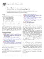
procedures are uniformly consistent to assure valid and reproducible results. Recommended equipment and sampling arrangements are shown in Fig. 2 and Fig. 3. Except in
circumstances where stationary interferences in the area around
the sampling location prohibits the use of the sampling
equipment as shown in Fig. 3, changes to the equipment should
not be allowed. Changes may produce inconsistent results.
6.2.1 Fig. 2 shows the recommended arrangement for sampling pulverized coal in a direct-fired system using a dustless
sampling connection with an aspirator and a cyclone collector.
In collecting the sample, turn on the compressed air to the
dustless connection and adjust to give a balanced pressure at
the connection. Insert the sampling tip into the dustless
connection with the tip facing directly into the coal-air stream.
Readjust the compressed air to give a balanced pressure with
the nozzle inserted. Traverse the fuel transport line across the
entire diameter of the pipe by moving at a uniform rate with the
tip facing directly into the coal-air stream. The aspirating air on
the cyclone collector may or may not be used, depending on
the static pressure in the fuel transport line, as discussed in
6.3.7.
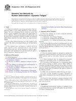
6.2.2 Fig. 3 shows detailed dimensions of a recommended
sampling tip. The area of the tip shown is 0.5 by 0.95 in. or
0.475 in.2 (12.7 by 24.1 mm or 306 mm2), which is the
projected area of the tip facing the coal-air stream. Other tip
configurations and dimensions can be employed provided they
permit the collection of an unbiased sample from the coal
stream. See Appendix X1.
5.1 In the pulverized coal storage system, the coal after
pulverization is conveyed into bins.
5.1.1 Collection of Gross Sample—Collect not less than ten
increments of representative pulverized coal preferably as it is
being discharged from the collector. This is best accomplished
by collecting increments of not less than 50 g at regular
intervals by means of a scoop, dipper, or a device capable of
removing an increment from a specific location within the
stream of pulverized coal. Place the increments in the sample
container and seal.
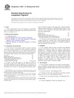
5.1.2 Preparation of the Laboratory Sample—A small riffle
(Fig. 1) can be used for mixing and dividing the sample by
splitting. An enclosed riffle is preferred. Mix the gross sample
by splitting and recombining the halves a minimum of two
times. Divide the sample amount by successive riffle splitting
operations on one half of the sample until the sample is divided
to approximately 500 g for the laboratory sample. To correctly
use the riffle, the sample must be poured over the side of a pan
(a third pan is necessary) and not from an end or corner, nor
from a container such as, a pail or jar. Transfer the sample to
a sample container and seal.
5.1.3 As an alternative to riffle mixing and splitting, the
sample can be prepared as follows: Place the gross sample on
a sheet of rubber, plastic, or paper and mix it by raising first one
corner of the cloth and then the other so as to roll the coal over
and over at least 20 times. After mixing, divide the sample.
Continue the operations of mixing and dividing until the
sample is divided sufficiently so that all of one of the divisions
weighs approximately 500 g. This shall constitute the laboratory sample.
6.3 Collection of Gross Sample:
6.3.1 In sampling, it is essential that the velocity into the
sampling tip be nearly the same as the velocity in the pipe. If
the velocity in the sampling tube is insufficient, the full quota
of the coarse particles will be entrained, but some of the fine
particles that should be caught will follow the air in passing
around the tip. If the velocity in the sampling tube is greater,
more than the proper number of fine particles will be drawn
into the sampling tip.
6.3.2 A procedure for confirming sample validity is included in Appendix X4.
6.3.3 A sample obtained in a given time should be weighed
and compared with the weight of coal passing through the fuel
transport line. The weight of the coal passing through the pipe
may be determined from the total coal to the pulverizer divided
by number of pipes. The weight of coal passing through the
fuel transport line, multiplied by the ratio of the cross-sectional
area of the sampling tip to that of the pipe, should be
approximately equal to the sample weight (see 6.3.9). For
example, if a pulverizer has an output of 63 000 lb of coal per
hour passing through six lines, and if each line is 15.25 in. (387
mm) in inside diameter, with a cross-sectional area of 182.65
6. Sampling, Direct-Fired System
6.1 In the direct-fired system, the coal is pulverized and
delivered directly to the furnace in an air stream. It is difficult
FIG. 1 Sample Divider (Riffle)
2
D197 − 87 (2012)
FIG. 2 Recommended Arrangement for Sampling Pulverized Coal in a Direct-Fired System
in.2 (1170 cm2) and if the standard sampler has a tip opening of
0.5 by 0.95 in. (12.7 mm by 24.1 mm) and a cross-sectional
area of 0.475 in.2 (306 mm2), the sample rate per minute with
100 % recovery should then be as follows:
give a recovery within the 90 and 110 % limits. Discard those
samples that do not meet the recovery limits.
6.3.6 If the static pressure in the fuel transport line is so high
that the recovery is above 110 % with all aspirator air shut off,
throttle the flow from the cyclone to reduce the recovery to the
desired range between 90 and 110 %. This can be done by
installing a valve or orifice at the cyclone collector vent
discharge (see Fig. 2).
6.3.7 Samples shall be taken by carefully traversing at least
two complete diameters 90° apart. Two common sampling
methods are the continuous transversing technique or the equal
area method. If preliminary samples taken at each individual
line show wide variations in fineness and recovery, better
Sample rate, lb/min = 63 000 lb/h-pulverizer × 1 h ⁄ 60 min × 1
pulverizer/6 lines × 0.475 in.2/sampler/182.65 in.2/line × 1 sampler/1 line = 0.455 lb/min-line (206 g/min-line)
Sampling for a 3-min period should then be 1.37 lb (618 g)
for 100 % recovery.
6.3.4 If the recovery is between 90 and 110 %, the sample
shall be considered satisfactory as to collection rate for the pipe
and flow velocities. See Appendix X2.
6.3.5 After taking one or two samples and weighing them
for confirmation, the collector vent control can be adjusted to
3
D197 − 87 (2012)
FIG. 3 Detail of Sampling Nozzle
fineness of all samples taken during the test or the fineness of
the composite sample.
locations should be used. The location shall preferably be in a
vertical pipe as far as possible from preceding bends, changes
of cross section, or valves. A distance of seven to ten times the
pipe diameter is desirable. Sampling connections shall be
cleared of accumulated coal before taking samples.
6.3.8 Precautions should be taken to keep the samples above
the water dew point during collection.
6.3.9 When the sampling points are in the pipes and a
pulverizer has two or more pipes, the total weight of the
samples from all the pipes should be compared with total coal
weight to check the recovery, as explained in 6.3.2 – 6.3.4.
6.3.10 When the air velocity and static pressure in each fuel
transport line are nearly equal, the same cyclone throttle setting
and the same air pressure at the aspirator should give about the
same sample tip velocity. Then, even if the coal is not equally
distributed in the several pipes, duplicate cyclone throttle
settings should result in samples from each pipe that will be
approximately proportional in weight to the coal distribution,
but the total should be between 90 and 110 % of the proportional total coal flow. Samples at each point should be taken for
equal time periods and not by equal amounts collected. Each
sample may be sieved separately and the weighted average
used to obtain the average fineness of the pulverizer output or
the samples may be thoroughly mixed and one sieve determination made of the mixture, since the sample from each line
represents the proper proportion of the pulverizer output.
6.3.11 In storage systems, take samples at the outlet of the
cyclone collector. If the sampling location is under suction,
provide the container with a cover that can be closed before it
is withdrawn from the sampling connection.
6.3.12 The fineness of pulverized coal samples taken in a
storage system shall be either the weighted average of the
NOTE 1—The collection of a valid representative sample requires both
properly maintained equipment and close attention to details by the
samplers. The collection is best accomplished by one person actually
sampling, assisted by a person to facilitate equipment and sample
handling.
7. Fineness Test
7.1 Drying Sample—Air-dry the entire laboratory sample in
a drying oven at 18 to 27°F (10 to 15°C) above room
temperature. Continue the drying until the loss in weight is not
more than 0.1 % ⁄h.
7.2 Dividing the Sample—After air-drying, divide the
sample amount to 50 to 100 g as described in 5.1.2 and 5.1.3.
7.3 Sieve Test:
7.3.1 Select the proper sieve sizes for the test and thoroughly clean each by carefully brushing and tapping to assure
that no solid particles from previous tests are trapped in the
meshes. Nest the sieves together with the coarsest mesh at the
top and in descending order with the finest mesh at the bottom.
Set a pan receiver at the bottom of the nest to receive the
undersize. Place 45 to 55 g of coal weighed to 60.05 g on the
top sieve and cover with a fitted cover to prevent loss.
7.3.2 Place the assembled set into the sieving machine and
make the necessary adjustments for the sieving operation.
Adjust the timer for a 10-min period and start the machine. For
hand sieving alternative, see Appendix X3.
7.3.3 At the end of the sieving period, remove the stack, slip
off the receiver pan, and carefully brush into the pan receiver
any particles that have adhered to the bottom surface of the
4
D197 − 87 (2012)
undersize material and is so calculated. If the loss is greater
than 1 % for coals having 75 % or less undersize or is greater
than 2 % for coals having more than 75 % undersize, discard
the results and repeat the determination.
bottom sieve. Carefully transfer all of the pan contents into
another receptacle and return the clean pan receiver to the
bottom of stacker sieves. Retain the transferred fines for
weighing.
7.3.4 Return the stacked sieves to the sieving machine, set
the timer for a 5-min period, and start the machine. At the end
of this interval, remove the stack and repeat the procedure
described in 7.3.3. However, this time collect the fines from the
pan receiver and those brushed from the under-surface of the
sieve and weigh. When the collected fines from the 5-min
sieving weigh less than 0.5 g, consider the sieving operation
complete. If the fines weigh in excess of 0.5 g, reassemble the
stack and repeat the sieving operation at 2-min intervals until
less than 0.2 g of fines are collected for a 2-min interval.
7.3.5 Combine the fines collected in all of the operations
from 7.3.3 and 7.3.4 and weigh on a balance sensitive to 0.01
g. Disassemble the sieves beginning with the largest. Material
that can be brushed from the bottom of a sieve shall be
considered to be part of the sample that has passed through that
sieve. This material can be brushed directly onto the next finer
sieve. Material that is lodged in the sieve shall be considered a
portion of the sample that was retained on that sieve. The sieve
can be placed over glazed paper, foil, or a pie pan and lodged
material brought onto that surface and then recombined with
the material retained on that sieve.
NOTE 3—An operator working at a site with a particular coal may
ascertain that in routine operations, differences in sample weights before
and after sieving are within such close tolerances that he may choose not
to weigh the undersize material. It should be recognized that results so
obtained are subject to question.
9. Report
9.1 The fineness test shall be reported as follows:
Retained on
USA Standard
No.
No.
No.
No.
No.
No.
No.
...
8 (2.36 mm)
16 (1.18 mm)
30 (600 µm)
50 (300 µm)
100 (150 µm)
200 (75 µm)
325 (45 µm)
Passing
USA Standard
...
No.
No.
No.
No.
No.
No.
No.
8 (2.36 mm)
16 (1.18 mm)
30 (600 µm)
50 (300 µm)
100 (150 µm)
200 (75 µm)
325 (45 µm)
%
...
...
...
...
...
...
...
...
For procedure to confirm sample validity, see Appendix X4
(See Fig. 4).
10. Precision and Bias
10.1 Repeatability—Duplicate determinations on splits of
the gross sample, by the same operator, using the same sieves,
shall check within 2 % of the material weight passing the finest
sieve.
NOTE 2—The procedure described in 7.3.4 and 7.3.5 is applicable to
samples from a normal dry-pulverizing process. If, for whatever reason,
the sample consists of a major percentage concentrated on an intermediate
size interval, sieving operations should be continued until it is confirmed
that less than 0.2 g of fines pass that sieve in a 2-min interval.
10.2 Reproducibility—Duplicate determinations on splits of
the gross sample, by different operators, using different sieves,
shall check within 4 % of the material weight passing the finest
sieve.
7.3.6 Weigh and record the amount of material collected
from each sieve surface, including the undersize material.
8. Calculations
10.3 Bias—The lack of a reference material precludes a bias
statement.
8.1 Calculate the fineness from the weights of the residues
on the sieves, including the undersize from the finest sieve, and
express as percentages of the weight of the original sample. A
difference between the original sample portion and cumulative
sieve weights is considered to be due to loss (or gain) of the
11. Keywords
11.1 fineness; pulverized coal; sampling; sieve analysis
5
D197 − 87 (2012)
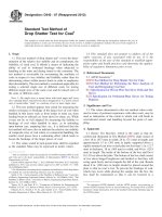
FIG. 4 Plot of Rosin and Rammler Equation for Use with Pulverized Coal
APPENDIXES
(Nonmandatory Information)
X1. ALTERNATE TIP CONFIGURATIONS
fineness matching that obtained with the recommended tip
design within the limits of reproducibility identified in 10.2.
X1.1 If tip configurations other than illustrated in Figs. 2
and 3 are used, their ability to permit the collection of an
unbiased sample shall be evaluated on the basis of sample
6
D197 − 87 (2012)
X2. EXTREME MALDISTRIBUTION
X2.1 If extreme maldistribution of coal exists among fuel
pipes, it may not be possible to obtain a recovery rate of 90 to
110 % in each line. In this case, use the procedure in 6.3.9 to
verify the recovery rate.
X3. FINENESS TEST BY HAND SIEVING
sieves into a sieving machine.
X3.1 For field testing or similar operations where a sieving
machine is not available, the test can be performed by a
hand-sieving operation. The object of the hand-sieving operation is to duplicate as nearly as possible the details of test as
performed by mechanical sieving. This can be accomplished as
described below.
X3.3 Instead, hold the nest of sieves with both hands and
move back and forth in a slightly circular orbit while resting on
a 1⁄4-in. (6.4-mm) plate (suggested dimensions 4 by 12 in.
(100 × 300 mm)). With each movement, the stack is permitted
to move over the plate edge and tap the table surface. The
above-described manual movement is designed to simulate the
rotation and tapping of machine sieving (see 4.4).
X3.2 Prepare the sieves and the sample amount as described
in 7.1, 7.2, and 7.3.1, with the exception of placing the nest of
X4. PROCEDURE FOR CONFIRMING SAMPLE VALIDITY
X4.1 Rosin and Rammler chart paper (Fig. 4) may be used
to confirm the validity of sampling. Fineness results plotted on
the chart paper should approach a straight line with possibly a
slight deviation at the extremes. Consistency in sampling
techniques is verified when duplicate results are confirmed by
duplication of the curve. Wide deviations from a straight-line
plot should be investigated to confirm reasons for the deviation.
ASTM International takes no position respecting the validity of any patent rights asserted in connection with any item mentioned
in this standard. Users of this standard are expressly advised that determination of the validity of any such patent rights, and the risk
of infringement of such rights, are entirely their own responsibility.
This standard is subject to revision at any time by the responsible technical committee and must be reviewed every five years and
if not revised, either reapproved or withdrawn. Your comments are invited either for revision of this standard or for additional standards
and should be addressed to ASTM International Headquarters. Your comments will receive careful consideration at a meeting of the
responsible technical committee, which you may attend. If you feel that your comments have not received a fair hearing you should
make your views known to the ASTM Committee on Standards, at the address shown below.
This standard is copyrighted by ASTM International, 100 Barr Harbor Drive, PO Box C700, West Conshohocken, PA 19428-2959,
United States. Individual reprints (single or multiple copies) of this standard may be obtained by contacting ASTM at the above
address or at 610-832-9585 (phone), 610-832-9555 (fax), or (e-mail); or through the ASTM website
(www.astm.org). Permission rights to photocopy the standard may also be secured from the Copyright Clearance Center, 222
Rosewood Drive, Danvers, MA 01923, Tel: (978) 646-2600; />
7