Astm d 88 07 (2013)
Bạn đang xem bản rút gọn của tài liệu. Xem và tải ngay bản đầy đủ của tài liệu tại đây (265.71 KB, 7 trang )
Designation: D88 − 07 (Reapproved 2013)
American Association State
Highway and Transportation Officials Standard
AASHTO No: T72
Method 304—Federal Test
Method Standard No. 791b
Replaces Method 4285 of Federal Test
Method Standard No. 141A
Standard Test Method for
Saybolt Viscosity1
This standard is issued under the fixed designation D88; the number immediately following the designation indicates the year of original
adoption or, in the case of revision, the year of last revision. A number in parentheses indicates the year of last reapproval. A superscript
epsilon (´) indicates an editorial change since the last revision or reapproval.
This standard has been approved for use by agencies of the U.S. Department of Defense.
D445 Test Method for Kinematic Viscosity of Transparent
and Opaque Liquids (and Calculation of Dynamic Viscosity)
D2161 Practice for Conversion of Kinematic Viscosity to
Saybolt Universal Viscosity or to Saybolt Furol Viscosity
D2170 Test Method for Kinematic Viscosity of Asphalts
(Bitumens)
D4057 Practice for Manual Sampling of Petroleum and
Petroleum Products
D4177 Practice for Automatic Sampling of Petroleum and
Petroleum Products
E1 Specification for ASTM Liquid-in-Glass Thermometers
E11 Specification for Woven Wire Test Sieve Cloth and Test
Sieves
E102 Test Method for Saybolt Furol Viscosity of Bituminous
Materials at High Temperatures
1. Scope
1.1 This test method covers the empirical procedures for
determining the Saybolt Universal or Saybolt Furol viscosities
of petroleum products at specified temperatures between 21
and 99°C (70 and 210°F). A special procedure for waxy
products is indicated.
NOTE 1—Test Methods D445 and D2170 are preferred for the determination of kinematic viscosity. They require smaller samples and less
time, and provide greater accuracy. Kinematic viscosities may be converted to Saybolt viscosities by use of the tables in Practice D2161. It is
recommended that viscosity indexes be calculated from kinematic rather
than Saybolt viscosities.
1.2 The values stated in SI units are to be regarded as the
standard. The values given in parentheses are for information
only.
1.3 This standard does not purport to address all of the
safety concerns, if any, associated with its use. It is the
responsibility of the user of this standard to establish appropriate safety and health practices and determine the applicability of regulatory limitations prior to use.
3. Terminology
3.1 Definitions:
3.1.1 Furol—an acronym of “Fuel and road oils.”
3.1.2 Saybolt Furol viscosity—the corrected efflux time in
seconds of 60 mL of sample flowing through a calibrated Furol
orifice under specified conditions. The viscosity value is
reported in Saybolt Furol seconds, abbreviated SFS, at a
specified temperature.
2. Referenced Documents
2
2.1 ASTM Standards:
D93 Test Methods for Flash Point by Pensky-Martens
Closed Cup Tester
D117 Guide for Sampling, Test Methods, and Specifications
for Electrical Insulating Oils of Petroleum Origin
D140 Practice for Sampling Bituminous Materials
D244 Test Methods and Practices for Emulsified Asphalts
3.1.3 Saybolt Universal viscosity—the corrected efflux time
in seconds of 60 mL of sample flowing through a calibrated
Universal orifice under specified conditions. The viscosity
value is reported in Saybolt Universal seconds, abbreviated
SUS, at a specified temperature.
1
This test method is under the jurisdiction of ASTM Committee D08 on Roofing
and Waterproofing and is the direct responsibility of Subcommittee D08.05 on
Solvent-Bearing Bituminous Compounds for Roofing and Waterproofing.
Current edition approved May 1, 2013. Published May 2013. Originally
approved in 1921. In 1923, combined with former Methods D47. Last previous
edition approved in 2007 as D88 – 07. DOI: 10.1520/D0088-07R13.
2
For referenced ASTM standards, visit the ASTM website, www.astm.org, or
contact ASTM Customer Service at For Annual Book of ASTM
Standards volume information, refer to the standard’s Document Summary page on
the ASTM website.
4. Summary of Test Method
4.1 The efflux time in seconds of 60 mL of sample, flowing
through a calibrated orifice, is measured under carefully
controlled conditions. This time is corrected by an orifice
factor and reported as the viscosity of the sample at that
temperature.
Copyright © ASTM International, 100 Barr Harbor Drive, PO Box C700, West Conshohocken, PA 19428-2959. United States
1
D88 − 07 (2013)
6.4 Saybolt Viscosity Thermometers , as listed in Table 1, for
reading the temperature of the sample. Each thermometer shall
conform to the requirements listed in Specification E1 for that
ASTM Thermometer Number.
5. Significance and Use
5.1 This test method is useful in characterizing certain
petroleum products, as one element in establishing uniformity
of shipments and sources of supply.
6.5 Bath Thermometers—Saybolt Viscosity thermometers,
or any other temperature-indicating means of equivalent accuracy.
5.2 See Guide D117 for applicability to mineral oils used as
electrical insulating oils.
5.3 The Saybolt Furol viscosity is approximately one tenth
the Saybolt Universal viscosity, and is recommended for
characterization of petroleum products such as fuel oils and
other residual materials having Saybolt Universal viscosities
greater than 1000 s.
6.6 Filter Funnel, as shown in Fig. 4, equipped with
interchangeable 150-µm (No. 100) and 75-µm (No. 200)
wire-cloth inserts meeting the requirements of Specification
E11 with respect to the wire cloth.
6.7 Receiving Flask, as shown in Fig. 5.
5.4 Determination of the Saybolt Furol viscosity of bituminous materials at higher temperatures is covered by Test
Method E102.
6.8 Timer, graduated in tenths of a second, and accurate to
within 0.1 % when tested over a 60-min interval. Electric
timers are acceptable if operated on a controlled frequency
circuit.
6. Apparatus
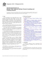
6.1 Saybolt Viscometer and Bath, as shown in Fig. 1 and
described in Annex A1.
7. Sampling
6.2 Withdrawal Tube, as shown in Fig. 2.
7.1 Sample the material in accordance with Practices D140,
D4057, or D4177, as appropriate.
6.3 Thermometer Support, as shown in Fig. 3.
NOTE 1—All dimensions are in millimetres (inches).
FIG. 1 Saybolt Viscometer with Universal and Furol Orifice
2
D88 − 07 (2013)
TABLE 1 ASTM Saybolt Viscosity Thermometers
Standard Test
Temperature
°C (°F)
ASTM
Thermometer
No.
21.1 (70)
17C (17F)
25.0 (77)
17C (17F)
37.8 (100)
18C (18F)
50.0 (122)
19C (19F)
54.4 (130)
19C (19F)
60.0 (140)
20C (20F)
82.2 (180)
21C (21F)
98.9 (210)
22C (22F)
Thermometer
Range° C (°F)
19 to 27
(66 to 80)
19 to 27
(66 to 80)
34 to 42
(94 to 108)
49 to 57
(120 to 134)
49 to 57
(120 to 134)
57 to 65
(134 to 148)
79 to 87
(174 to 188)
95 to 103
(204 to 218)
Subdivisions,° C (°F)
0.1 (0.2)
0.1 (0.2)
0.1 (0.2)
0.1 (0.2)
0.1 (0.2)
0.1 (0.2)
0.1 (0.2)
0.1 (0.2)
8. Preparation of Apparatus
8.1 Use a Universal orifice or tip for lubricants and distillates with efflux times greater than 32 s to give the desired
accuracy. Liquids with efflux times greater than 1000 s are not
conveniently tested with this orifice.
8.2 Use a Furol orifice or tip for residual materials with
efflux times greater than 25 s to give the desired accuracy. See
also 5.3.
8.3 Clean the viscometer thoroughly with an appropriate
solvent of low toxicity; then remove all solvent from the
viscometer and its gallery. Clean the receiving flask in the same
manner.
NOTE 2—The plunger commonly supplied with the viscometer should
never be used for cleaning; its use might damage the overflow rim and
walls of the viscometer.
8.4 Set up the viscometer and bath in an area where they
will not be exposed to drafts or rapid changes in air
temperature, and dust or vapors that might contaminate a
sample.
NOTE 1—All dimensions are in millimetres (inches).
FIG. 2 Withdrawal Tube for Use with Saybolt Viscometer
8.5 Place the receiving flask (Fig. 5) beneath the viscometer
so that the graduation mark on the flask is from 100 to 130 mm
(4 to 5 in.) below the bottom of the viscometer tube, and so that
the stream of oil will just strike the neck of the flask.
8.6 Fill the bath to at least 6 mm (1⁄4 in.) above the overflow
rim of the viscometer with an appropriate bath medium
selected from Table 2.
8.7 Provide adequate stirring and thermal control for the
bath so that the temperature of a test sample in the viscometer
will not vary more than 60.03°C (60.05°F) after reaching the
selected test temperature.
8.8 Do not make viscosity measurements at temperatures
below the dew point of the room’s atmosphere.
8.9 For calibration and referee tests, keep the room temperature between 20 and 30°C (68 and 86°F), and record the
actual temperature. However room temperatures up to 38°C
(100°F) will not introduce errors in excess of 1 %.
NOTE 1—All dimensions are in millimetres (inches).
FIG. 3 Thermometer Support
3
D88 − 07 (2013)
NOTE 1—All dimensions are in millimetres (inches).
FIG. 4 Filter Funnel for Use with Saybolt Viscometer
9. Calibration and Standardization
viscosity levels at all temperatures.
9.1 Calibrate the Saybolt Universal viscometer at periodic
intervals by measuring the efflux time at 37.8°C (100°F) of an
appropriate viscosity oil standard, following the procedure
given in Section 10. See Annex A2 for viscosity oil standards
available.
9.3 Calibrate the Saybolt Furol viscometer at 50.0°C
(122°F) in the same manner as above, using a viscosity oil
standard having a minimum efflux time of 90 s.
9.4 Viscometers or orifices requiring corrections greater
than 1.0 % shall not be used in referee testing.
9.2 The efflux time of the viscosity oil standard shall equal
the certified Saybolt viscosity value. If the efflux time differs
from the certified value by more than 0.2 %, calculate a
correction factor, F, for the viscometer as follows:
F 5 V/t
10. Procedure
10.1 Establish and control the bath temperature at the
selected test temperature.
10.1.1 Standard test temperatures for measuring Saybolt
Universal viscosities are 21.1, 37.8, 54.4, and 98.9°C (70, 100,
130, and 210°F).
10.1.2 Standard test temperatures for measuring Saybolt
Furol viscosities are 25.0, 37.8, 50.0, and 98.9°C (77, 100, 122,
and 210°F).
(1)
where:
V = certified Saybolt viscosity of the standard, and
t
= measured efflux time at 37.8°C (100°F), s.
NOTE 3—If the calibration is based on a viscosity oil standard having an
efflux time between 200 and 600 s, the correction factor applies to all
4
D88 − 07 (2013)
10.5.3 Immerse the flask in a bath of boiling water for 30
min.
10.5.4 Mix well, remove the sample from the boiling water
bath, wipe the outside of the flask dry, and strain the sample
through the 75-µm (No. 200) wire cloth in the filter funnel
directly into the viscometer until the level is above the
overflow rim.
10.6 Stir the sample in the viscometer with the appropriate
viscosity thermometer equipped with the thermometer support
(Fig. 3). Use a circular motion at 30 to 50 rpm in a horizontal
plane. When the sample temperature remains constant within
0.03°C (0.05°F) of the test temperature during 1 min of
continuous stirring, remove the thermometer.
NOTE 4—Never attempt to adjust the temperature by immersing hot or
cold bodies in the sample. Such thermal treatment might affect the sample
and the precision of the test.
10.7 Immediately place the tip of the withdrawal tube (Fig.
2) in the gallery at one point, and apply suction to remove oil
until its level in the gallery is below the overflow rim. Do not
touch the overflow rim with the withdrawal tube; the effective
liquid head of the sample would be reduced.
NOTE 1—All dimensions are in millimetres.
FIG. 5 Receiving Flask
10.8 Check to be sure that the receiving flask is in proper
position; then snap the cork from the viscometer using the
attached cord, and start the timer at the same instant.
10.1.3 Other standard test temperatures in use include 60.0
and 82.2°C (140 and 180°F).
10.9 Stop the timer the instant the bottom of the oil
meniscus reaches the graduation mark on the receiving flask.
Record the efflux time in seconds to the nearest 0.1 s.
10.2 Insert a cork stopper, having a cord attached for its
easy removal, into the air chamber at the bottom of the
viscometer. The cork shall fit tightly enough to prevent the
escape of air, as evidenced by the absence of oil on the cork
when it is withdrawn later as described.
11. Calculation and Report
11.1 Multiply the efflux time by the correction factor for the
viscometer determined in 9.2.
10.3 If the selected test temperature is above room
temperature, the test may be expedited by preheating the
sample in its original container to not more than 1.7°C (3.0°F)
above the test temperature. Never preheat any sample to within
28°C (50°F) of its flash point (see Test Methods D93), because
volatility losses might alter its composition.
11.2 Report the corrected efflux time as the Saybolt Universal or Saybolt Furol viscosity of the oil at the temperature at
which the test was made.
11.2.1 Report values below 200 SUS or SFS to the nearest
0.1 s. Report values of 200 s or higher to the nearest whole
second.
10.4 Stir the sample well; then strain it through the 150-µm
(No. 100) wire cloth in the filter funnel directly into the
viscometer until the level is above the overflow rim.
12. Precision and Bias
10.5 The viscosities of steam-refined cylinder oils, black
lubricating oils, residual fuel oils, and similar waxy products
can be affected by their thermal histories. Use the following
preheating procedure with such products to obtain uniform
results at temperatures below 93°C (200°F):
10.5.1 Heat the sample in its original container to about
50°C (122°F), with stirring and shaking to dissolve and blend
waxy materials. Probe the bottom of the container with a
stirring rod to be certain that all waxy materials are in solution,
and mix well.
10.5.2 Pour about 100 mL into a 125-mL Erlenmeyer flask.
Stopper loosely with a cork or rubber stopper.
12.1 Results should not differ from the mean by more than
the following (see Note 5):
12.1.1 Repeatability (one operator and apparatus)—1 %.
12.1.2 Reproducibility (different operators and apparatus)—
2 %.
NOTE 5—For petroleum products, the precision and bias is based on
data from Test Method E102. For emulsion, use precision and bias
statement in Test Method D244, Section 38.
13. Keywords
13.1 bituminous materials; kinematic; saybolt; viscosity
5
D88 − 07 (2013)
TABLE 2 Recommended Bath Media
Standard Test
Temperature,
°C (°F)
21.1
25.0
37.8
50.0
54.4
60.0
82.2
98.9
A
(70)
(77)
(100)
(122)
(130)
(140)
(180)
(210)
Recommended Bath Medium
water
water
water, or oil of 50 to 70 SUS viscosity at 37.8°C (100°F)
water, or oil of 120 to 150 SUS viscosity at 37.8°C (100°F)
water, or oil of 120 to 150 SUS viscosity at 37.8°C (100°F)
water, or oil of 120 to 150 SUS viscosity at 37.8°C (100°F)
water or oil of 300 to 370 SUS viscosity at 37.8°C (100°F)
oil of 330 to 370 SUS viscosity at 37.8°C (100°F)
Max Temp
Differential,A
°C (°F)
Bath Temperature Control
Functional Precision,
°C (°F)
±0.05 (0.10)
±0.05 (0.10)
±0.15 (0.25)
+ 0.20 (0.35)
+ 0.30 (0.50)
+ 0.60 (1.0)
+ 0.80 (1.5)
+ 1.10 (2.0)
±0.03
±0.03
±0.03
±0.03
±0.03
±0.06
±0.06
±0.06
(0.05)
(0.05)
(0.05)
(0.05)
(0.05)
(0.1)
(0.1)
(0.1)
Maximum permissible difference between bath and sample temperatures at the time of the test.
ANNEXES
(Mandatory Information)
A1. SAYBOLT VISCOMETER AND ACCESSORIES
A1.1 Viscometer—The viscometer, illustrated in Fig. 1,
shall be constructed entirely of corrosion-resistant metal,
conforming to dimensional requirements shown in Fig. 1. The
orifice tip, Universal or Furol, may be constructed as a
replaceable unit in the viscometer. Provide a nut at the lower
end of the viscometer for fastening it in the bath. Mount
vertically in the bath and test the alignment with a spirit level
on the plane of the gallery rim. Provide a cork or other suitable
means to prevent the flow of sample until the start of the test;
a small chain or cord may be attached to the cork to facilitate
rapid removal.
A1.2 Bath—The bath serves both as a support to hold the
viscometer in a vertical position as well as the container for the
bath medium. Equip the bath with effective insulation and with
an efficient stirring device. Provide the bath with a coil for
heating and cooling and with thermostatically controlled heaters capable of maintaining the bath within the functional
precision given in Table 2. The heaters and coil should be
located at least 30 mm from the viscometer. Provide a means
for maintaining the bath medium at least 6 mm (0.25 in.) above
the overflow rim. The bath media are given in Table 2.
A2. VISCOSITY STANDARDS
routine calibrations at other temperatures as shown in Table
A2.1. Other reference liquids, suitable for routine calibrations,
may be established by selecting stable oils covering the desired
range and determining their viscosities in a viscometer calibrated with a standard conforming to ASTM requirements.
A2.1 Saybolt Viscosity Standards—Viscosity oil standards
conforming to ASTM requirements have certified Saybolt
viscosity values established by cooperative determinations of
kinematic viscosity values. The kinematic values are converted
to Saybolt Universal and Saybolt Furol viscosity values by
means of conversion tables given in Practice D2161. The
approximate Saybolt viscosities are shown in Table A2.1.
A2.3 Routine Calibrations—The viscosity standards may
also be used for routine calibrations at other temperatures as
shown in Table A2.1.
A2.2 Standards Conforming to ASTM Saybolt Viscosity
Standards —The viscosity standards may also be used for
6
D88 − 07 (2013)
TABLE A2.1 Saybolt Viscosity Oil StandardsA
NOTE 1—All values are nominal and will vary with lot.
Viscosity Oil
Standard
S3
S6
S20
N26
N35
N44
S60
N75
N100
N140
S200
N250
N350
N415
S600
S2000
At 37.8°C
(100°F)
At 98.9°C
(210°F)
At 50°C
(122°F)
SUS
mm2/s
SUS
mm2/s
SUS
mm2/s
36
46
100
130
170
220
280
380
500
720
925
1300
1570
2180
...
...
3.0
6.0
20
27
35
48
60
82
110
160
200
280
340
470
...
...
...
...
...
...
...
...
...
...
...
...
105
140
160
200
240
360
...
...
...
...
...
...
...
...
...
...
20
29
32
41
50
72
...
...
...
...
...
...
...
...
...
...
...
...
...
...
120
...
...
...
...
...
...
...
...
...
...
...
...
...
...
...
310
...
A
These viscosity oil standards are available in 0.5-L containers from the Cannon
Instrument Co., 2139 High Tech Rd., State College, PA 16803.
ASTM International takes no position respecting the validity of any patent rights asserted in connection with any item mentioned
in this standard. Users of this standard are expressly advised that determination of the validity of any such patent rights, and the risk
of infringement of such rights, are entirely their own responsibility.
This standard is subject to revision at any time by the responsible technical committee and must be reviewed every five years and
if not revised, either reapproved or withdrawn. Your comments are invited either for revision of this standard or for additional standards
and should be addressed to ASTM International Headquarters. Your comments will receive careful consideration at a meeting of the
responsible technical committee, which you may attend. If you feel that your comments have not received a fair hearing you should
make your views known to the ASTM Committee on Standards, at the address shown below.
This standard is copyrighted by ASTM International, 100 Barr Harbor Drive, PO Box C700, West Conshohocken, PA 19428-2959,
United States. Individual reprints (single or multiple copies) of this standard may be obtained by contacting ASTM at the above
address or at 610-832-9585 (phone), 610-832-9555 (fax), or (e-mail); or through the ASTM website
(www.astm.org). Permission rights to photocopy the standard may also be secured from the Copyright Clearance Center, 222
Rosewood Drive, Danvers, MA 01923, Tel: (978) 646-2600; />
7