Astm d 562 10 (2014)
Bạn đang xem bản rút gọn của tài liệu. Xem và tải ngay bản đầy đủ của tài liệu tại đây (160.62 KB, 7 trang )
Designation: D562 − 10 (Reapproved 2014)
Standard Test Method for
Consistency of Paints Measuring Krebs Unit (KU) Viscosity
Using a Stormer-Type Viscometer1
This standard is issued under the fixed designation D562; the number immediately following the designation indicates the year of
original adoption or, in the case of revision, the year of last revision. A number in parentheses indicates the year of last reapproval. A
superscript epsilon (´) indicates an editorial change since the last revision or reapproval.
This standard has been approved for use by agencies of the U.S. Department of Defense.
1. Scope
5. Significance and Use
1.1 This test method covers the measurement of Krebs Unit
(KU) viscosity to evaluate the consistency of paints and related
coatings using the Stormer-type viscometer.
5.1 This test method provides values that are useful in
specifying and controlling the consistency of paints, such as
consumer or trade sales products.
1.2 The values stated in SI units are to be regarded as the
standard. The values given in parentheses are for information
only.
1.3 This standard does not purport to address all of the
safety concerns, if any, associated with its use. It is the
responsibility of the user of this standard to establish appropriate safety and health practices and determine the applicability of regulatory limitations prior to use.
METHOD A
6. Apparatus
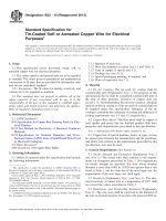
6.1 Viscometer, Stormer, with the paddle-type rotor as illustrated in Fig. 1 and Fig. 2. The stroboscopic timer attachment
in Fig. 1 can be removed and the instrument used without it but
with a sacrifice of speed and accuracy. The stroboscopic timer
gives the 200 r/min reading directly.
6.2 Container, 500-mL (1-pt), 85 mm (33⁄8 in.) in diameter.
2. Referenced Documents
6.3 Thermometer—An ASTM Stormer Viscosity thermometer having a range from 20 to 70°C and conforming to the
requirements for Thermometer 49C, as prescribed in Specification E1. In addition, temperature measuring devices such as
non-mercury liquid-in-glass thermometers, thermocouples, or
platinum resistance thermometers that provide equivalent or
better accuracy and precision, that cover the temperature range
for thermometer 49C, may be used.
2.1 ASTM Standards:2
E1 Specification for ASTM Liquid-in-Glass Thermometers
3. Terminology
3.1 Definitions of Terms Specific to This Standard:
3.1.1 consistency, n—load in grams to produce a rotational
frequency of 200 r/min (Stormer Viscometer).
3.1.2 Krebs units (KU), n—values of a scale commonly used
to express the consistency of paints generally applied by brush
or roller.
3.1.2.1 Discussion—This scale is a function of the “load to
produce 200-r/min” scale.
6.4 Stopwatch, or suitable timer measuring to 0.2 s.
6.5 Weights, a set covering the range from 5 to 1000 g.
7. Materials
7.1 Two standard oils, calibrated in absolute viscosity
(poise), that are within the viscosity range of the coatings to be
measured. These oils should differ in viscosity by at least 5 P.
4. Summary of Test Method
4.1 The load required to produce a rotational frequency of
200 r/min for an offset paddle rotor immersed in a paint is
determined.
NOTE 1—The normal range of the Stormer is covered by oils having
viscosities of 4 P (70 KU), 10 P (85 KU), and 14 P (95 KU).
7.1.1 Suitable standards are silicone, hydrocarbon, linseed,
and castor oils. Silicone and hydrocarbon oils calibrated in
poises are commercially available. Uncalibrated linseed and
castor oils may be calibrated with any apparatus that provides
measurements of absolute viscosity.
1
This test method is under the jurisdiction of ASTM Committee D01 on Paint
and Related Coatings, Materials, and Applications and is the direct responsibility of
Subcommittee D01.24 on Physical Properties of Liquid Paints and Paint Materials.
Current edition approved Dec. 1, 2014. Published December 2014. Originally
approved in 1947. Last previous edition approved in 2010 as D562 – 10. DOI:
10.1520/D0562-10R14.
2
For referenced ASTM standards, visit the ASTM website, www.astm.org, or
contact ASTM Customer Service at For Annual Book of ASTM
Standards volume information, refer to the standard’s Document Summary page on
the ASTM website.
Copyright © ASTM International, 100 Barr Harbor Drive, PO Box C700, West Conshohocken, PA 19428-2959. United States
1
D562 − 10 (2014)
L 5 ~ 610O1906.6 D ! /30
where:
O = viscosity of oil in poises and
D = density of oil.
8. Calibration4
8.1 Remove the rotor and weight carrier from the viscometer. Make sure the string is wound evenly on the drum and
does not overlap itself.
8.2 Attach a 5-g weight onto the string and then release the
brake. If the viscometer starts to run from this dead start and
continues to run through several revolutions of the string drum,
it is satisfactory for use. If it does not start unaided when the
5-g weight is applied, the instrument should be reconditioned.
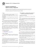
8.3 Check the dimensions of the paddle-type rotor. They
should be within 0.1 mm (60.004 in.) of the dimensions shown
in Fig. 2.
8.4 Select two standard oils having assigned values of load
to produce 200 r/min within the range of the values expected
for the coatings to be measured (see 7.1).
FIG. 1 Stormer Viscometer with Paddle-Type Rotor and Stroboscopic Timer
8.5 Adjust the temperature of the standard oils to 25 6
0.2°C. The temperature of the Stormer apparatus should be the
same. If the specified temperature cannot be obtained, record
the temperature of the oil at the beginning and end of test to
0.2°C.
8.6 Determine the load in grams to produce 200 r/min with
each of the two oils, using either Procedure A described in
Section 9 or Procedure B described in Section 10.
8.6.1 If the oil temperature was not at 25 6 0.2°C during the
test, correct the measured load in grams for the deviation from
that temperature.
NOTE 2—Load corrections for deviations of oil temperature from the
specified temperature can be made by means of a previously established
plot of load versus oil temperature (see Appendix X1).
8.7 If the measured load (corrected for any temperature
deviation from standard) is within 615 % of the assigned load
values for the oils, the Stormer apparatus can be considered to
be in satisfactory calibration.
9. Procedure A (Without Stroboscopic Attachment)
9.1 Thoroughly mix the sample and strain it into a 500-mL
(1-pt) container to within 20 mm (3⁄4 in.) of the top.
9.2 Bring the temperature of the specimen to 25 6 0.2°C
and maintain it at that temperature during the test. The
temperature of the Stormer apparatus should be the same.
9.2.1 If the specified temperature cannot be obtained, record
the temperature of the specimen at the beginning and end of
test to 0.2°C.
NOTE 1—1 in. = 25.4 mm.
FIG. 2 Paddle-Type Rotor for Use With Stormer Viscometer
9.3 When the temperature of the specimen has reached
equilibrium, stir it vigorously, being careful to avoid entrapping air, and place the container immediately on the platform
7.1.2 Assign a value of load to produce 200 r/min to each oil
by converting its viscosity value in poises to load in grams by
the following equation:3
3
Geddes, J. A., and Dawson, D. H., “Calculation of Viscosity From Stormer
Viscosity Data,” Industrial and Engineering Chemistry, Vol 34, 1942, p. 163.
4
Jackson, C. F., and Madson, W. H., “A Method for the Standardization of Krebs
Modified Stormer Viscometers,” ASTM Bulletin, No. 161, 1949.
2
D562 − 10 (2014)
of the viscometer so that the paddle-type rotor is immersed in
the material to the mark on the shaft of the rotor.
9.4 Place weights on the hanger of the viscometer and
determine a load that will produce 100 revolutions in the range
of 25 to 35 s.
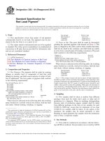
FIG. 4 Stroboscopic Lines Appearing as Multiples that May be
Observed Before 200-r/min Reached
9.5 Using the information gained in 9.4, select two loads
that will provide two different readings (time to give 100
revolutions) within the range of 27 to 33 s. Make these
measurements from a running start, that is, permit the rotor to
make at least 10 revolutions before starting the timing for 100
revolutions.
NOTE 4—Table 1 has been constructed so that it is not necessary to
interpolate between loads to obtain the KU corresponding to the load to
produce 100 revolutions in 30 s. The table provides KU values computed
for a range of 27 to 33 s for 100 revolutions.
9.6 Repeat the measurements outlined in 9.5 until two
readings for each load are obtained that agree within 0.5 s.
11.2 Procedure B:
11.2.1 If desired, determine from Table 2 the KU value
corresponding to the load to produce 200 r/min.
10. Procedure B (With Stroboscopic Timer)
12. Report
10.1 Follow Procedure A (9.1 – 9.3) for the preparation of
the specimen.
12.1 Report the following information:
12.1.1 The load in grams to produce 200 r/min (100
revolutions in 30 s),
12.1.2 The calculated KU,
12.1.3 The temperature of the specimen during the test and
whether a correction was applied for any deviation from 25°C,
and
12.1.4 Whether Procedure A or Procedure B was used.
10.2 Connect the lamp circuit of the stroboscopic attachment to an electrical power source.
10.3 Place weights on the hanger of the viscometer and
determine a load that will produce 100 revolutions in the range
from 25 to 35 s.
10.4 Using the information gained in 10.3, select a weight
(to the nearest 5 g) that will produce the 200-r/min pattern (Fig.
3) on the stroboscopic timer, that is, where the lines appear to
be stationary.
10.4.1 Lines moving in the direction of paddle rotation
indicate a speed greater than 200 r/min and therefore, weight
should be removed from the hanger. Conversely, lines moving
opposite to direction of paddle rotation indicate a speed less
than 200 r/min and weight should be added.
13. Precision and Bias
13.1 Precision—On the basis of a study in which determinations were made on five paints by two operators at each of
five laboratories on each of two different days; the withinlaboratory coefficient of variation was found to be 3 % in load
grams or 1.5 % in KU, and the between-laboratory coefficient
of variation was found to be 10 % in load grams or 4 % in KU.
13.1.1 The following criteria should be used for judging the
acceptability of results at the 95 % confidence level.
13.1.1.1 Repeatability—Two results each the mean of two
measurements, obtained on the same material by the same
operator at different times should be considered suspect if they
differ by more than 1.7 % in KU.
13.1.1.2 Reproducibility—Two results, each the mean of
two measurements on the same material, obtained by operators
in different laboratories should be considered suspect if they
differ by more than 5.1 % in KU.
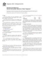
NOTE 3—There are other patterns that appear at speeds other than 200
r/min (See Fig. 4). The pattern for 200 r/min should be determined before
running any tests.
10.5 Repeat the determination in 10.4 until a consistent
value of load is obtained (that is, to within 5 g).
11. Calculation
11.1 Procedure A:
11.1.1 Calculate the load to within 5 g, to produce 100
revolutions in 30 s by interpolating between the load weights
recorded for the readings made between 27 and 33 s for 100
revolutions.
11.1.2 Correct the load determined for any deviation of the
specimen temperature from the specified temperature (see
Appendix X1).
11.1.3 If desired, determine from Table 1 the KU corresponding to the load to produce 100 revolutions in 30 s.
METHOD B (Digital Display Stormer-Type Viscometer)
14. Apparatus
14.1 Viscometer, Digital Display, with the paddle-type rotor
as illustrated in Fig. 1 and Fig. 5.
14.2 Container, 500 mL (1 pt), 85 mm (3 3⁄8 in. in diameter.
14.3 Thermometer, ASTM Stormer viscosity thermometer
having a range from 20 to 70°C and conforming to the
requirements for Thermometer 49C as prescribed in Specification E1.
15. Materials
15.1 Standard Oils, two, calibrated in absolute viscosity that
are within the viscosity range of the coatings to be measured.
These oils should differ in viscosity by at least 25 KU.
FIG. 3 Stroboscopic Lines Opening When Timer is Adjusted to
Exactly 200 r/min
3
27
28
29
30
31
32
33
Seconds
for 100
Revolutions
49
51
53
54
55
56
57
75
57
59
60
61
62
63
64
63
65
66
67
68
69
70
69
70
71
72
73
74
75
74
75
76
77
78
79
80
79
80
81
82
82
83
84
83
84
85
86
86
87
88
86
87
88
89
90
90
91
89
90
91
92
93
93
94
92
93
94
95
95
96
96
95
96
97
98
98
99
99
97
98
99
100
100
101
101
100
100
101
102
102
103
103
102
102
103
104
104
105
105
104
105
105
106
106
107
107
Krebs Units
106 109 111
107 110 112
107 110 112
108 110 112
108 111 113
109 111 113
109 112 114
113
114
114
114
115
115
116
114
115
115
116
116
116
117
116
117
117
118
118
118
119
118
118
119
120
120
120
121
120
120
121
121
122
122
122
121
121
122
122
123
123
123
123
123
124
124
125
125
125
124
124
125
125
126
126
126
126
126
127
127
128
128
128
127
127
128
128
129
129
129
129
129
130
130
131
131
131
130
130
131
131
132
132
132
131
131
132
133
133
133
134
132
132
133
134
134
134
135
133
133
134
135
135
135
136
134
134
135
136
136
136
137
136
137
137
138
138
138
139
138
139
139
140
140
140
141
Load, g
100 125 150 175 200 225 250 275 300 325 350 375 400 425 450 475 500 525 550 575 600 625 650 675 700 725 750 775 800 825 850 875 900 950 1000
TABLE 1 Krebs’ Stormer Chart with Interpolations
D562 − 10 (2014)
4
D562 − 10 (2014)
TABLE 2 Krebs Units Corresponding to Load Required to Produce 200-r/min Rotation
(For use with Stormer Viscometer equipped with Stroboscopic Timer)
Grams
KU
Grams
KU
Grams
KU
Grams
KU
Grams
KU
Grams
KU
Grams
KU
Grams
KU
Grams
KU
Grams
KU
Grams
KU
100 61
105 62
200 82
205 83
300 95
400 104
500 112
600 120
700 125
800 131
900 136
1000 140
110 63
115 64
210 83
215 84
310 96
410 105
510 113
610 120
710 126
810 132
910 136
1010 140
120 65
125 67
220 85
225 86
320 97
420 106
520 114
620 121
720 126
820 132
920 137
1020 140
130 68
135 69
230 86
235 87
330 98
430 106
530 114
630 121
730 127
830 133
930 137
1030 140
140 70
145 71
240 88
245 88
340 99
440 107
540 115
640 122
740 127
840 133
940 138
1040 140
150 72
155 73
250 89
255 90
350 100
450 108
550 116
650 122
750 128
850 134
950 138
1050 141
160 74
165 75
260 90
265 91
360 101
460 109
560 117
660 123
760 129
860 134
960 138
1060 141
70 53
75 54
170 76
175 77
270 91
275 92
370 102
470 110
570 118
670 123
770 129
870 135
970 139
1070 141
80 55
85 57
180 78
185 79
280 93
285 93
380 102
480 110
580 118
680 124
780 130
880 135
980 139
1080 141
90 58
95 60
190 80
195 81
290 94
295 94
390 103
490 111
590 119
690 124
790 131
890 136
990 140
1090 141
16. Calibration
16.1 Check the dimensions of the paddle-type rotor. They
should be within 60.1 mm (0.004 in.) of the dimensions shown
in Fig. 2.
16.2 Select two standard oils having viscosities in KU
within the range of the values expected for the coatings to be
measured (see 15.1).
16.3 Adjust the temperature of the standard oils to 25 6
0.2°C. The temperature of the viscometer should be the same.
If the specified temperature cannot be obtained, record the
temperature of the oil at the beginning and end of the test to
0.2°C.
16.4 If the oil temperature was not at 25 6 0.2°C during the
test, correct the measured KU viscosity for the deviation from
that temperature.
NOTE 5—Corrections for deviations of oil temperature from the
specified temperature can be made by means of a previously established
plot of load grams versus oil temperature (see Appendix X1).
16.5 If the measured viscosity (corrected for any temperature deviation from standard) is within 65 % of the specified
KU values for the standard oils, the viscometer can be
considered to be in satisfactory calibration.
17. Procedure
FIG. 5 Digital Stormer-Type Viscometer
17.1 Thoroughly mix the specimen and pour into a 500–mL
(1–pt) container to within 20 mm (3⁄4 in.) of the top.
17.2 Bring the temperature of the specimen to 25 6 0.2°C,
and maintain it at that temperature during the test. The
temperature of the viscometer should be the same.
15.2 Suitable Hydrocarbon Oils, calibrated in KU and
traceable to NIST, available commercially.
5
D562 − 10 (2014)
17.3 If the specified temperature cannot be obtained, record
the temperature of the specimen at the beginning and end of the
test to 0.2°C.
18. Report
18.1 Report the following information:
18.1.1 The measured Krebs Units (KU) and the Grams
(gm).
18.1.2 The temperature of the specimen during the test and
whether a correction was applied for any deviation from 25°C.
17.4 When the temperature of the specimen has reached
equilibrium, stir it vigorously, being careful to avoid entrapping air, move the operating handle to the top position, pull the
front locator out and place the container immediately on the
base of the viscometer against the locating pins and release the
front locator locking and centering the can.
19. Precision and Bias
19.1 Precision—On the basis of a study in which measurements were made on five paints by two operators in each of six
laboratories (five with Brookfield KU-1 viscometer and one
with an electronic Stormer viscometer) on each of two different
days, the following criteria should be used for judging the
acceptability of results at the 95 % confidence level.
19.1.1 Repeatability—Two results, each the mean of two
measurements on the same material by the same operator at
different times, should be considered suspect if they differ by
more than 2.0 % in KU.
19.1.2 Reproducibility—Two results, each the mean of two
measurements on the same material, obtained by operators in
different laboratories should be considered suspect if they
differ by more than 5.0 % in KU.
17.5 Turn on the main power switch and select either KU or
Gram (gm) display. Be sure that the HOLD reading switch is in
the up position.
17.6 Move the operating handle to the lower (immersing the
paddle spindle into the specimen). The fluid should be close to
the immersion groove on the paddle shaft. The paddle will start
rotating when it is within about 12 mm (1⁄2 in.) of the lower
position.
17.7 Wait 5 s for the display reading to stabilize.
17.8 Press the HOLD reading switch down to “hold” the
display and use the display selector knob to display KU or
gram units, or both.
19.2 Bias—Since there is no accepted reference material for
this test method, bias cannot be determined.
17.9 Raise the operating handle to the top position, and let
the specimen drain from the paddle spindle.
20. Keywords
17.10 Loosen the thumb screw and remove the paddle
spindle for cleaning.
20.1 consistency; Krebs units (KU); Stormer-type viscometer; viscosity
APPENDIX
(Nonmandatory Information)
X1. EFFECT OF SPECIMEN TEMPERATURE ON STORMER CONSISTENCY
X1.1 For maximum accuracy in determining the effect of
specimen temperature on consistency, measurements should be
performed at three different specimen temperatures covering
the range of interest. The change in load or KU per 1°C change
can be determined from these results.
Mean Value at
25°C
Load,
KU
g
value
Hydrocarbon oil No. 1
Hydrocarbon oil No. 2
Hydrocarbon oil No. 3
Bodied linseed oil
Heavily bodied linseed oil
Water-based exterior paint
Water-based exterior paint
X1.2 It has been observed that the consistency of an oil is
considerably more sensitive to temperature than is the consistency of a paint.
X1.3 Some typical effects of temperatures on the consistency of oils and paints are given below:
6
149
217
286
195
440
300
425
72
85
93
81
108
95
105
Change per 1°C
Change
Load,
KU
g
value
14
18
11
8
40
4
4
2.5
2.0
1.5
1.0
2.0
0.5
0.5
D562 − 10 (2014)
ASTM International takes no position respecting the validity of any patent rights asserted in connection with any item mentioned
in this standard. Users of this standard are expressly advised that determination of the validity of any such patent rights, and the risk
of infringement of such rights, are entirely their own responsibility.
This standard is subject to revision at any time by the responsible technical committee and must be reviewed every five years and
if not revised, either reapproved or withdrawn. Your comments are invited either for revision of this standard or for additional standards
and should be addressed to ASTM International Headquarters. Your comments will receive careful consideration at a meeting of the
responsible technical committee, which you may attend. If you feel that your comments have not received a fair hearing you should
make your views known to the ASTM Committee on Standards, at the address shown below.
This standard is copyrighted by ASTM International, 100 Barr Harbor Drive, PO Box C700, West Conshohocken, PA 19428-2959,
United States. Individual reprints (single or multiple copies) of this standard may be obtained by contacting ASTM at the above
address or at 610-832-9585 (phone), 610-832-9555 (fax), or (e-mail); or through the ASTM website
(www.astm.org). Permission rights to photocopy the standard may also be secured from the Copyright Clearance Center, 222
Rosewood Drive, Danvers, MA 01923, Tel: (978) 646-2600; />
7