jiun-haw lee, david n. liu, shin-tson wu introdution to flat panel displays (bookos.org)
Bạn đang xem bản rút gọn của tài liệu. Xem và tải ngay bản đầy đủ của tài liệu tại đây (12.53 MB, 281 trang )
Introduction to
Flat Panel Displays
Wiley-SID Series in Display Technology
Series Editor:
Anthony C. Lowe
Consultant Editor:
Michael A. Kriss
Display Systems: Design and Applications
Lindsay W. MacDonald and Anthony C. Lowe (Eds)
Electronic Display Measurement: Concepts, Techniques, and Instrumentation
Peter A. Keller
Projection Displays
Edward H. Stupp and Matthew S. Brennesholtz
Liquid Crystal Displays: Addressing Schemes and Electro-Optical Effects
Ernst Lueder
Reflective Liquid Crystal Displays
Shin-Tson Wu and Deng-Ke Yang
Colour Engineering: Achieving Device Independent Colour
Phil Green and Lindsay MacDonald (Eds)
Display Interfaces: Fundamentals and Standards
Robert L. Myers
Digital Image Display: Algorithms and Implementation
Gheorghe Berbecel
Flexible Flat Panel Displays
Gregory Crawford (Ed.)
Polarization Engineering for LCD Projection
Michael G. Robinson, Jianmin Chen, and Gary D. Sharp
Fundamentals of Liquid Crystal Devices
Deng-Ke Yang and Shin-Tson Wu
Introduction to Microdisplays
David Armitage, Ian Underwood, and Shin-Tson Wu
Mobile Displays: Technology and Applications
Achintya K. Bhowmik, Zili Li, and Philip Bos (Eds)
Photoalignment of Liquid Crystalline Materials:
Physics and Applications
Vladimir G. Chigrinov, Vladimir M. Kozenkov and Hoi-Sing Kwok
Projection Displays, Second Edition
Matthew S. Brennesholtz and Edward H. Stupp
Introduction to Flat Panel Displays
Jiun-Haw Lee, David N. Liu and Shin-Tson Wu
Introduction to
Flat Panel Displays
By
Jiun-Haw Lee
National Taiwan University, Taiwan
David N. Liu
Industrial Technology Research Institute, Taiwan
Shin-Tson Wu
University of Central Florida, USA
This edition first published 2008
© 2008 John Wiley & Sons Ltd.
Registered office
John Wiley & Sons Ltd, The Atrium, Southern Gate, Chichester, West Sussex,
PO19 8SQ, United Kingdom
For details of our global editorial offices, for customer services and for information about how to apply for
permission to reuse the copyright material in this book please see our website at www.wiley.com.
The right of the author to be identified as the author of this work has been asserted in accordance
with the Copyright, Designs and Patents Act 1988.
All rights reserved. No part of this publication may be reproduced, stored in a retrieval system, or transmitted,
in any form or by any means, electronic, mechanical, photocopying, recording or otherwise, except as permitted
by the UK Copyright, Designs and Patents Act 1988, without the prior permission of the publisher.
Wiley also publishes its books in a variety of electronic formats. Some content that appears in print
may not be available in electronic books.
Designations used by companies to distinguish their products are often claimed as trademarks. All brand names
and product names used in this book are trade names, service marks, trademarks or registered trademarks of
their respective owners. The publisher is not associated with any product or vendor mentioned in this book.
This publication is designed to provide accurate and authoritative information in regard to the subject matter
covered. It is sold on the understanding that the publisher is not engaged in rendering professional services.
If professional advice or other expert assistance is required, the services of a competent professional should
be sought.
Library of Congress Cataloging-in-Publication Data
Lee, Jiun-Haw.
Introduction to flat panel displays / by Jiun-Haw Lee,
David N. Liu, and Shin-Tson Wu.
p. cm.
Includes bibliographical references and index.
ISBN 978-0-470-51693-5 (cloth)
1. Flat panel displays. I. Liu, David N. II. Wu, Shin-Tson. III. Title.
TK7882.I6L436 2008
621.3815
422—dc22
2008032204
A catalogue record for this book is available from the British Library.
ISBN: 978-0-470-51693-5
Set in 9/11pt Times by Integra Software Services Pvt. Ltd, Pondicherry, India
Printed in Great Britain by Antony Rowe Ltd, Chippenham, Wiltshire
Contents
Series Editor’s Foreword xi
About the authors xiii
Preface xv
Acknowledgements xvii
1 Introduction 1
1.1 Flat panel displays 1
1.2 Emissive and nonemissive displays 3
1.3 Display specifications 3
1.3.1 Physical parameters 3
1.3.2 Brightness and color 5
1.3.3 Contrast ratio 5
1.3.4 Spatial and temporal characteristics 5
1.3.5 Efficiency and power consumption 6
1.3.6 Flexible displays 6
1.4 Applications of flat panel displays 6
1.4.1 Liquid crystal displays 7
1.4.2 Light-emitting diodes 7
1.4.3 Plasma display panels 8
1.4.4 Organic light-emitting devices 8
1.4.5 Field emission displays 9
References 9
2 Color science and engineering 11
2.1 Introduction 11
2.2 The eye 12
2.3 Colorimetry 15
2.3.1 Trichromatic space 15
2.3.2 CIE 1931 colorimetric observations 16
2.3.3 CIE 1976 uniform color system 19
2.3.4 Color saturation and color gamut 21
2.3.5 Light sources 22
vi Contents
2.3.5.1 Sunlight and blackbody radiators 22
2.3.5.2 Backlights of transmissive displays 23
2.3.5.3 Color rendering index 24
2.3.6 Photometry 25
2.4 Production and reproduction of colors 27
Homework problems 28
References 28
3 Thin-film transistors 31
3.1 Introduction 31
3.2 Basic concepts of crystallized semiconductor materials 31
3.2.1 Band structure of crystallized semiconductors 32
3.2.2 Intrinsic and extrinsic semiconductors 36
3.3 Disordered semiconductors 38
3.3.1 Amorphous silicon 39
3.3.2 Polycrystalline silicon 41
3.4 Thin-film transistor characteristics 43
3.5 Passive matrix and active matrix driving schemes 47
3.6 Non-silicon-based thin-film transistors 53
Homework problems 55
References 56
4 Liquid crystal displays 57
4.1 Introduction 57
4.2 Transmissive thin-film transistor liquid crystal displays 58
4.3 Liquid crystal materials 60
4.3.1 Phase transition temperatures 60
4.3.2 Eutectic mixtures 61
4.3.3 Dielectric constants 62
4.3.4 Elastic constants 65
4.3.5 Rotational viscosity 65
4.3.6 Optical properties 66
4.3.7 Refractive indices 67
4.3.7.1 Wavelength effect 67
4.3.7.2 Temperature effect 68
4.4 Liquid crystal alignment 70
4.5 Homogeneous cell 71
4.5.1 Phase retardation effect 72
4.5.2 Voltage-dependent transmittance 73
4.6 Twisted nematic 73
4.6.1 Optical transmittance 74
4.6.2 Viewing angle 75
4.6.3 Film-compensated TN cells 76
4.7 In-plane switching 78
4.7.1 Device structure 78
4.7.2 Voltage-dependent transmittance 79
4.7.3 Viewing angle 79
4.7.4 Phase compensation films 80
4.8 Fringe field switching 81
Contents vii
4.9 Vertical alignment 83
4.9.1 Voltage-dependent transmittance 83
4.9.2 Response time 83
4.9.3 Overdrive and undershoot voltage method 85
4.9.4 Multidomain vertical alignment 86
4.10 Optically compensated bend cell 88
4.10.1 Voltage-dependent transmittance 88
4.10.2 Compensation films for OCB 89
4.10.3 No-bias bend cell 91
4.11 Transflective liquid crystal displays 91
4.11.1 Introduction 91
4.11.2 Dual cell gap transflective LCDs 93
4.11.3 Single cell gap transflective LCDs 95
4.12 Future directions 101
Homework problems 101
References 103
5 Plasma display panels 109
5.1 Introduction 109
5.2 Physics of gas discharge 109
5.2.1 I–V characteristics 110
5.2.2 Penning reaction and Paschen curve 111
5.2.3 Priming mechanism 112
5.3 Plasma display panels 112
5.3.1 DC PDP 112
5.3.2 AC PDP 113
5.3.3 Panel processes 115
5.4 Front plate techniques 117
5.4.1 Substrate 118
5.4.2 Sustain electrode 118
5.4.3 Dielectric 119
5.4.4 Protection layer 119
5.5 Rear plate techniques 120
5.5.1 Substrate 121
5.5.2 Address electrode 121
5.5.3 Dielectric 121
5.5.4 Barrier rib 122
5.5.5 Phosphor 124
5.6 Assembly and aging techniques 126
5.6.1 Sealing layer formation and panel alignment 126
5.6.2 Sealing, gas purging and display gas filling 127
5.6.3 Aging 128
5.7 System techniques 128
5.7.1 Cell operation mechanism 129
5.7.2 Driving 130
5.7.3 Energy saving 130
5.7.4 PDP issues 132
Homework problems 132
References 132
viii Contents
6 Light-emitting diodes 137
6.1 Introduction 137
6.2 Material systems 140
6.2.1 AlGaAs and AlGaInP material systems for red and yellow LEDs 142
6.2.2 GaN-based systems for green, blue and UV LEDs 143
6.2.3 White LEDs 145
6.3 Diode characteristics 147
6.3.1 The p-layer and n-layer 148
6.3.2 Depletion region 149
6.3.3 J–V characteristics 152
6.3.4 Heterojunction structures 153
6.3.5 Quantum well, quantum wire and quantum dot structures 154
6.4 Light-emitting characteristics 155
6.4.1 Recombination model 156
6.4.2 L–J characteristics 157
6.4.3 Spectral characteristics 158
6.5 Device fabrication 161
6.5.1 Epitaxy 161
6.5.2 Process flow and device structure design 164
6.5.3 Extraction efficiency improvement 165
6.5.4 Package 167
6.6 Applications 168
6.6.1 Traffic signals, electronic signage and huge displays 169
6.6.2 LCD backlight 169
6.6.3 General lighting 172
Homework problems 173
References 174
7 Organic light-emitting devices 177
7.1 Introduction 177
7.2 Energy states in organic materials 178
7.3 Photophysical processes 179
7.3.1 Franck–Condon principle 180
7.3.2 Fluorescence and phosphorescence 182
7.3.3 Jablonski diagram 183
7.3.4 Intermolecular processes 184
7.3.4.1 Energy transfer process 184
7.3.4.2 Excimer and exciplex formation 185
7.3.4.3 Quenching process 187
7.3.5 Quantum yield calculation 187
7.4 Carrier injection, transport and recombination 189
7.4.1 Richardson–Schottky thermionic emission 190
7.4.2 SCLC, TCLC and PF mobility 192
7.4.3 Charge recombination 193
7.4.4 Electromagnetic wave radiation 193
7.5 Structure, fabrication and characterization 195
7.5.1 Device structure 196
7.5.1.1 Two-layer OLED 197
7.5.1.2 Dopant in the matrix as the EML 198
Contents ix
7.5.1.3 HIL, EIL and p–i–n structure 200
7.5.1.4 Top-emission and transparent OLEDs 203
7.5.2 Polymer OLEDs 204
7.5.3 Device fabrication 205
7.5.3.1 Thin-film formation 206
7.5.3.2 Encapsulation and passivation 209
7.5.3.3 Device structures for AM driving 210
7.5.4 Electrical and optical characteristics 211
7.5.5 Degradation mechanisms 213
7.6 Improvement of internal quantum efficiency 218
7.6.1 Phosphorescent OLEDs 218
7.6.2 Tandem structure 220
7.6.3 White OLEDs 222
7.7 Improvement of extraction efficiency 224
Homework problems 225
References 226
8 Field emission displays 233
8.1 Introduction 233
8.2 Physics of field emission 233
8.2.1 Work function and field enhancement 233
8.2.2 Vacuum mechanism 236
8.3 FED structure and display mechanism 237
8.4 Emitter 238
8.4.1 Spindt emitter 239
8.4.2 CNT emitter 240
8.4.3 Surface conduction emitter 243
8.5 Panel process 244
8.6 Field emission array plate techniques 247
8.7 Phosphor plate techniques 248
8.8 Assembly and aging techniques 249
8.8.1 Spacer 251
8.8.2 Sealing layer formation and panel alignment 251
8.8.3 Sealing 252
8.8.4 Evacuation and sealing off 252
8.8.5 Aging 253
8.9 System techniques 253
Homework problems 254
References 254
Index 259
Series Editor’s Foreword
Article 2 of the bylaws of the Society for Information Display begins “1. The purpose of SID shall be:
a) To encourage the scientific, literary and educational advancement of information display and its allied
arts and sciences ’’. This book series was begun eleven years ago with the express object of extending
that encouragement, which in the printed form amounted to publishing conference proceedings and a
Journal of peer refereed papers, to the provision of a series of books which would satisfy the needs of
scientists and engineers working in the wide and complex field of displays. More recently in 2006, we
published “Fundamentals of Liquid Crystal Devices’’ by Deng-Ke Yang and Shin-Tson Wu (who – not
coincidentally – is a co-author of this book). That book extended the readership because it was written
primarily as a post graduate textbook.
This latest volume in the series extends that educational scope still further by describing the operating
principles and the methods of fabrication of technologies used or of potential use in flat panel displays,
their methods of addressing, systems aspects and the underpinning science. Although general books
on flat panel displays have been published in the past, this is the first comprehensive flat panel display
textbook to have been written at this academic level. Its readership and its use will extend far beyond post
graduate courses as it offers in a single volume material of great value to practising industrial engineers
and scientists across the whole range of flat panel technologies.
In my foreword, I usually provide a précis of the contents of a book, but the authors have done this so
comprehensively that such an effort on my part would be superfluous. It merely remains for me to thank
them for the great effort they have put into writing this book and wholeheartedly to commend it to our
present and expanding readership.
Anthony C Lowe
Series Editor
Braishfield, UK.
About the authors
Jiun-Haw Lee
Jiun-Haw Lee received BSEE, MSEE and PhD degrees in electrical engineering in 1994, 1995 and 2000,
respectively, all from National Taiwan University, Taipei, Taiwan. From 2000 to 2003 he was with the
RiTdisplay Corporation as the director. In 2003 he joined the faculty of National Taiwan University in
the Graduate Institute of Photonics and Optoelectronics and the Department of Electrical Engineering,
where he is currently an associate professor. His research interests include organic light-emitting devices,
display technologies and solid-state lighting.
Dr Lee is a member of the IEEE, OSA, MRS and SPIE. He received the Exploration Research Award
of Pan Wen Yuan Foundation and Lam Research Award in both 2005 and 2006. He has published over
40 journal papers, 100 conference papers and 20 issued patents.
David N. Liu
David N. Liu has been the director of the Strategic Planning Division in the Display Technology Center
(DTC) of the Industrial Technology Research Institute (ITRI) since 2006. He worked on IC and field
emission displays at ERSO (Electronics Research and Service Organization)/ITRI and Bellcore (Bell
Communication Research) from 1983 to 1996. He started his research and development work on plasma
display panels at Acer Peripheral Inc. and AUO from 1996 to 2002. After his service at AUO, he was in
charge of the flat panel display technology division in ERSO/ITRI until 2006.
Dr Liu received his PhD degree in electrical engineering from New Jersey Institute of Technology in
1992. He has over 45 issued patents, 18 published papers and a contributed chapter of the Semiconductor
Manufacturing Handbook (McGraw-Hill, 2005). He also successfully developed field emission displays,
plasma display panels and flat panel displays followed by the receipt of many awards from ITRI, Photonics
Industry and Technology DevelopmentAssociation,Administration Bureau of Science Base Industry Park
and the Ministry of EconomicAffairs (MOEA). He was also a recipient of the Outstanding Project Leader
Award from MOEA in 2006.
Shin-Tson Wu
Shin-Tson Wu is a PREP professor at the College of Optics and Photonics, University of Central Flor-
ida (UCF). Prior to joining UCF in 2001, Dr Wu worked at Hughes Research Laboratories (Malibu,
California) for 18 years. He received his PhD in physics from the University of Southern California (Los
Angeles) and BS in physics from National Taiwan University (Taipei).
Prof. Wu has co-authored four books: Fundamentals of Liquid Crystal Devices (Wiley, 2006), Intro-
duction to Microdisplays (Wiley, 2006), Reflective Liquid Crystal Displays (Wiley, 2001) and Optics
and Nonlinear Optics of Liquid Crystals (World Scientific, 1993), six book chapters, over 300 journal
publications and 75 issued and pending patents.
xiv About the authors
Prof. Wu is a fellow of the IEEE, OSA, SID and SPIE. He is a recipient of the SPIE G.G. Stokes
award, SID Jan Rajchman Prize, SID Special Recognition Award, SID Distinguished Paper Award,
Hughes team achievement award, Hughes Research Laboratories outstanding paper award, UCF Distin-
guished Researcher Award and UCF Research Incentive Award. He was the founding editor-in-chief of
the IEEE/OSA Journal of Display Technology.
Preface
Flat panel displays (FPDs) are everywhere in our daily lives: mobile phones, notebooks, monitors, TVs,
traffic signals and electronic signage are a few examples. Several FPD technologies, such as liquid crystal
displays (LCDs), plasma display panels (PDPs), light-emitting diodes (LEDs), organic light-emitting
devices (OLEDs) and field emission displays (FEDs), have been developed. They coexist because each
technology has its own unique properties and applications.
However, due to the diversity of display materials and operating mechanisms, there has not been a
textbook covering the fundamental physics of such a wide spectrum of display technologies. There are
books dedicated to a specific display technology or book chapters covering different display technologies.
This book is intended as a textbook for senior undergraduate and graduate students with a wide variety
of backgrounds, such as electrical engineering, electronics, material science, applied physics and optical
engineering. It can also be used as a reference book for engineers and scientists working in display
industries. Parts of the material in this book and its organization follow the course ‘Introduction to
display technologies’, which has been taught by Jiun-Haw Lee in the Graduate Institute of Photonics and
Optoelectronics (GIPO) and Department of Electrical Engineering, National Taiwan University (NTU),
Taipei, Taiwan, since 2003.
This book introduces basic operation principles and underlying physics for thin-film transistors (TFTs)
LCDs, PDPs, LEDs, OLEDs and FEDs in each chapter. The LCD is a nonemissive display. From the elec-
trical viewpoint, each pixel is a light switch driven by a TFT. To reduce leakage current of the capacitor,
the liquid crystal material should have a high resistivity. Moreover, to achieve a high contrast ratio, most
direct-view TFT LCDs require two absorption-type sheet polarizers. These polarizers not only reduce the
light efficiency but also limit the LCD’s viewing angle. Therefore, phase compensation films are required
for wide-view LCDs. In contrast, the PDP is an emissive display. It can be considered as consisting of mil-
lions of miniature fluorescent lamps on a single panel. LEDs and OLEDs are electroluminescent devices
with crystallized semiconductors and amorphous organic materials, respectively. Compared with liquid
crystal materials which are also organic compounds, OLED materials should exhibit a low resistivity to
reduce ohmic losses.A FED is a type of flat cathode ray tube, which has all the advantages of this mature
technology.
In this book, both basic physics and practical issues (such as material requirements, device configura-
tions, fabrication methods and driving techniques) of different display technologies are addressed. Each
display technology is at a different development stage; some are more mature than others. Generally
speaking, they are still advancing so rapidly that it is difficult to keep up with the technological advance-
ments. Thus, in this introductory book we have decided to emphasize the fundamental science and only
highlight the key technological advancements of each technology.
Another objective of this book is to provide background knowledge for readers from interdisciplin-
ary fields to stimulate new ideas. Since display technologies cover very broad scientific spectra, any
breakthrough from any aspect may result in substantial progress in this industry. Sometimes there is not
only competition but also cooperation among different display technologies. For example, LCDs and
LEDs are distinct technologies for different display applications. However, LEDs can be also used as
xvi Preface
backlights for LCDs. As a result, the color gamut is widened, the dynamic contrast ratio is enhanced
and power consumption is reduced. After reading this book, one may expect to have a whole picture of
display technologies from scientific, technical and engineering viewpoints. There are different kinds of
technologies suitable for different sizes (ranging from smaller than an inch to more than a hundred inches
in diagonal measurement) and applications (such as outdoor, indoor and mobile displays). Furthermore,
this book may serve as a stepping stone to more advanced research and development.
The organization of this book is as follows. Chapter 1 introduces the classifications and specifica-
tions of display technologies, which are guidelines for developing a display and judging performance.
Applications suitable for different technologies (LCD, PDP, LED, OLED and FED) are also illustrated.
Displays are used to produce or reproduce color images. In Chapter 2 we introduce the stages of color
formation from a scientific viewpoint. Then, the chromaticity diagram is used to quantitatively describe
colors. Finally, one can use the background of color science to engineer the color performance of a dis-
play. Chapter 3 describes the TFTs based on semiconductor material, which are used to drive LCDs and
OLEDs. Since this is an introductory textbook, some basic semiconductor physics are first introduced,
which is also useful knowledge for Chapter 6. Material aspects of amorphous silicon and polycrystalline
silicon are discussed. Then, device structures and their performances are introduced. Finally, driving
techniques and circuits for LCDs and OLEDs are demonstrated. Emerging TFT technologies, such as
organic and oxide TFTs, are briefly discussed.
In Chapter 4 we begin with basic liquid crystal compound structures, mixture formulations and their
physical properties, and then extend the discussion to device structures and display characteristics. Three
major LCDs are introduced: transmissive, reflective and transflective. Most modern LCDs are of the
transmissive type. However, these displays might be washed out by direct sunlight. In contrast, reflective
displays work well under sunlight but are not readable in dark ambient. To retain the good images of a
transmissive display while keeping good sunlight readability, transflective LCDs have been developed.
Chapter 5 gives an overview of PDP fundamentals. We begin with a discussion of the physics of a
gas discharge, covering the reactions of gas discharges and I–V characteristics. DC PDP and AC PDP
panels as well as surface discharge and vertical discharge approaches are introduced. The panel process
technologies and useful process approaches are also described. Finally, we discuss system techniques
with cell operation and driving mechanism.
Semiconductor LEDs are discussed in Chapter 6.Westart from the material system because this determ-
ines the emission wavelength. Electrical properties of LEDs, typically p–n junctions, and corresponding
optical characteristics are then discussed. The fabrication process is introduced, which highlights the
practical electrical, optical and thermal issues. Finally, applications of LEDs for displays are described.
Chapter 7 describes OLEDs, with fabrication processes and operation principles similar to LCDs and
LEDs, respectively. The chapter starts from the material aspect. Opto-physical processes in an organic
material are introduced. Electrical injection and transport in organic materials are then described. Device
structures and fabrication are then discussed. One serious disadvantage of an OLED is its short lifetime;
this issue is also addressed. In Chapter 8 an overview of FED fundamentals is provided. We begin by
discussing the physics of field emission, covering the field enhancement and vacuum mechanism. FED
structure, display mechanism and various emitters are introduced. The advantages and disadvantages of
using low- and high-voltage phosphor are compared. The panel process technology and useful process
approaches are also described. Finally, system techniques are discussed.
Jiun-Haw Lee, Taiwan
David N. Liu, Taiwan
Shin-Tson Wu, Florida, USA
Acknowledgements
Jiun-Haw Lee would like to thank his colleagues Profs. I-Chun Cheng, Chih-I Wu, Jian-Jang Huang,
Yuh-Renn Wu, Hoang-Yan Lin and Ding-Wei Huang of GIPO, NTU, for many helpful discussions.
Mr Jia-Xing Lin of ITRI is gratefully acknowledged for kindly providing useful information about TFT
technologies. Dr Lee is also grateful to his students in NTU and Dr Zhibing Ge of the University of Central
Florida, who helped to prepare drawings, references, homework problems and examples, together with
providing valuable remarks and comments from a reader’s perspective.
David N. Liu is grateful to his colleagues in ITRI and AUO for useful discussions, and Ted Knoy for
his professional proofreading. In particular, he would like to express his gratitude to his wife Janice for
her patience and support during the period of writing the book.
Shin-Tson Wu is deeply indebted to his present and former group members at the University of
Central Florida for their numerous technical contributions, and to Chi-Mei Optoelectronics for the funding
support. He is grateful to his wife Cho-Yan for spiritual support during the writing of the book.
1
Introduction
1.1 Flat panel displays
A display is an interface containing information which stimulates human vision. Information may be
pictures, animation, movies and articles. One can say that the functions of a display are to produce or
reproduce colors and images. Using ink to write, draw or print on paper is a traditional display, like
a painting or a book. However, the content of such a traditional display is motionless and typically
inerasable. In addition, a light source, synthetic or natural, is needed for reading a book or seeing a
picture. There are lots of electronic displays that use an electronic signal to create images on a panel and
stimulate the human eye. Typically, they can be classified as emissive and nonemissive. Emissive displays
emit light from each pixel which constitutes an image on the panel. In contrast, nonemissive displays
modulate light, by means of absorption, reflection, refraction and scattering, to display colors and images.
For a nonemissive display, a light source is needed. Hence, these can be classified into transmissive and
reflective displays. One of the most successful display technologies for home entertainment is the cathode
ray tube (CRT), which is in widespread use in televisions (TVs). CRT is already a mature technology
which has the advantages of self-emission, wide viewing angle, fast response, good color saturation, long
lifetime and good image quality. However, a major disadvantage is its bulky size. The depth of a CRT is
roughly equal to the length and width of the panel. For example, a monitor’s depth is about 40 cm for a
19-inch (38.6 cm × 30.0 cm) CRT with an aspect ratio of 4:3. Hence, it is not very portable. The bulky
size and heavy weight limit its applications.
In this book, we introduce various types of flat panel displays (FPDs). As the name implies, these
displays have a relatively thin profile, i.e. several centimeters or less. For instance, the liquid crys-
tal display (LCD) is presently the dominant FPD technology with diagonal sizes ranging from less
than 1 inch (microdisplay) to over 100 inches. Such a display is usually driven by thin-film transistors
(TFTs). A liquid crystal (LC) is a light modulator because it does not emit light. Hence, a backlight
module is required for a transmissive LCD. In most LCDs, two crossed polarizers are employed in order
to obtain a high contrast ratio. The use of two polarizers limits the maximum transmittance to about
35–40 %, unless a polarization conversion scheme is implemented. Moreover, the optical axes of two
crossed polarizers are no longer perpendicular to each other when viewed at oblique angles. A LC is a
birefringent medium which means its electro-optic effects are dependent on the incident light direction.
Therefore, the viewing angle of a LCD is an important issue. Most wide-view LCDs require multiple
optical phase compensation films; one for compensating the crossed polarizer and another for the birefrin-
gent LC. Film-compensated transmissive LCDs exhibit a high contrast ratio, high resolution, crisp image,
good color saturation and wide viewing angle. However, the displayed images can be washed out under
Introduction to Flat Panel Displays J H. Lee, D.N. Liu and S T. Wu
c
2008 John Wiley & Sons, Ltd
2 Introduction to Flat Panel Displays
direct sunlight. For example, if we use a notebook computer at outdoor ambient, the images may not be
readable. This is because the reflected sunlight from the LCD surface is much brighter than that trans-
mitted from the backlight so that the signal-to-noise ratio is low. A broadband antireflection coating will
definitely help to improve the sunlight readability.
Another way to improve sunlight readability is to use reflective LCDs.
1
A reflective LCD uses ambient
light to produce the displayed images. It does not carry a backlight; thus, its weight is reduced. A wrist-
watch is such an example. Most reflective LCDs have inferior performances compared to the transmissive
ones in contrast ratio, color saturation and viewing angle. Moreover, at dark ambient a reflective LCD is
not readable. As a result, its application is rather limited.
To overcome the sunlight readability issue while maintaining high image quality, a hybrid display
called a transflective liquid crystal display (TR-LCD) has been developed.
2
In a TR-LCD, each pixel is
divided into two subpixels: transmissive (T) and reflective (R). The area ratio between T and R can be
adjusted depending on the application. For example, if the display is mostly used outdoors, then one can
design to have 80 % reflective area and 20 % transmissive area. In contrast, if the display is mostly used
indoors, then one can have 80 % transmissive area and 20 % reflective area. Within this TR-LCD family,
there are still some varieties: double cell gap versus single cell gap, and double TFTs versus single TFT.
These approaches are trying to solve the optical path length disparity between the T and R subpixels.
In the transmissive mode the light from the backlight unit passes through the LC layer once, but in the
reflective mode the ambient light traverses the LC medium twice. To balance the optical path length, we
could make the cell gap of the T subpixels twice as thick as that of the R subpixels. This is the so-called
dual cell gap approach. The single cell gap approach has a uniform cell gap throughout the T and R
regions. To balance the different optical path lengths, several approaches have been developed, e.g. dual
TFTs, dual fields (stronger field for T region and weaker field for R region) and dual alignments. Presently,
the majority of TR-LCDs adopt the double cell gap approach for two reasons: (1) both T and R modes can
achieve maximum light efficiency, and (2) the gamma curve matching between the voltage-dependent
transmittance (VT) and reflectance (VR) is almost perfect. However, the double cell gap approach has
two shortcomings: first, the T region has a slower response time than the R region because its cell gap
is about twice as thick as that of the R region; second, the viewing angle is relatively narrow, especially
when homogeneous cells are employed. To widen the viewing angle, a special rod-like LC polymeric
compensation film has to be used. Chapter 4 gives detailed descriptions of various types of LCDs.
A plasma display panel (PDP) is an emissive display which can be thought of as very many miniature
fluorescent lamps on a panel. As an emissive display it typically has a better display performance, such
as good color saturation and wide viewing angle. Due to the limitation of fabrication, the pixel size of a
PDP cannot be too small. For a finite pixel size, the video content is increased by enlarging the panel size.
PDPs are suitable for large-screen applications. In 2008, Panasonic demonstrated a 150-inch PDP TV
with 4096 × 2160 pixels. This resolution is four times higher than that of the present full high-definition
television (HDTV).
Light-emitting diodes (LEDs) and organic light-emitting devices (OLEDs) are electroluminescent
devices with semiconductor and organic materials, respectively. Electrons and holes recombine within
the emissive materials, where the bandgap of the materials determines the emission wavelength.
A field emission display (FED) uses sharp emitters to generate electrons. These electrons bombard the
phosphors that are present to emit red (R), green (G) and blue (B) light. A FED is like a ‘flat’ CRT. Due
to the mature technologies developed in CRTs, FEDs exhibit all the advantages of CRTs plus the smaller
panel thickness.
Compared to conventional displays (such as books, magazines and newspapers), electronic displays
(such as TVs, mobile phones and monitors) are rigid because they are typically fabricated on glass
substrates. Flexible FPDs are emerging. Several approaches have been developed, such as electrophoretic
displays and polymer-stabilized cholesteric displays. Flexible displays are thin, robust and lightweight.
In the remainder of this chapter, we first introduce FPD classifications in terms of emissive and none-
missive displays, where nonemissive displays include transmissive and reflective displays. Specifications
Introduction 3
of FPDs are then outlined. Finally, the FPD technologies described in the later chapters of this book are
briefly introduced.
1.2 Emissive and nonemissive displays
Both emissive and nonemissive FPDs have been developed. For emissive displays, each pixel emits light
with different intensity and color which stimulate the human eye directly. CRTs, PDPs, LEDs, OLEDs
and FEDs are emissive displays. An emitter is called Lambertian when the luminances from different
viewing directions are the same. Most emissive displays are Lambertian emitters which results in a wide
viewing angle performance. Also, due to the self-emissive characteristics, they can be used even under
very low ambient light. When such displays are turned off, they are completely dark (ignoring the ambient
reflection). Hence, display contrast ratios (see also Section 1.3.3) are high.
Displays that do not emit light themselves are called nonemissive displays. A LCD is a nonemissive
display in which the LC molecules in each pixel work as an independent light switch. The external
voltage reorients the LC directors which causes phase retardation. As a result, the incident light from
the backlight unit or ambient is modulated. Most high-contrast LCDs use two crossed polarizers. The
applied voltage controls the transmittance of the light through the polarizers. If the light source is behind
the display panel, the display is called a transmissive display. It is also possible to use ambient light as
the light source. This resembles the concept of a conventional display, such as reading a book, which is
called a reflective display. Since no backlight is needed in a reflective display, its power consumption is
relatively low.
In a very bright environment, images of emissive displays and transmissive LCDs can be washed out.
In contrast, reflective displays exhibit an even higher luminance as the ambient light increases. However,
they cannot be used in a dim environment. Hence, transflective LCDs have been developed, which are
described in Chapter 4.
1.3 Display specifications
In this section, we introduce some specifications which are generally used to describe and judge FPDs
from the viewpoints of mechanical, electrical and optical characteristics. FPDs can be smaller than
1 inch for projection displays, 2–4 inches for mobile phones and personal digital assistants, 7–9 inches
for car navigation systems, 8–18 inches for notebook computers, 10–25 inches for desktop computers and
more than 100 inches for direct-view TVs. For different FPDs, their requirements for pixel resolutions
also differ. Luminance and color are two important characteristics which directly affect the display
performances. Dependences of these two parameters to viewing angles, uniformity, lifetime and response
time should be addressed when describing the performances of an FPD. Contrast ratio is another important
parameter, which changes with different ambient environments.
1.3.1 Physical parameters
The basic physical parameters of an FPD include display size, aspect ratio, resolution and pixel format.
The size of a display is typically described by diagonal length, in units of inches. For example, a 15-inch
display means the diagonal of the viewable area of this display is 38.1 cm. There are three kinds of
display format: landscape, equal and portrait, corresponding to the display width being larger than, equal
to and smaller than its length. Most monitors and TVs use landscape format with a width-to-length ratio,
which is called the ‘aspect ratio’, of 4:3, 16:9 or 16:10, typically.
An FPD typically consists of a ‘dot matrix’ which can display images and characters. To increase
resolution, one may use more dots in a display. Table 1.1 lists some standard resolutions of FPDs. For
4 Introduction to Flat Panel Displays
Table 1.1 Resolution of FPDs.
Abbreviation Full name Resolution
VGA Video graphics array 640 × 480
SVGA Super video graphics array 800 × 600
XGA Extended graphics array 1024 × 768
SXGA Super extended graphics array 1280 × 1024
UXGA Ultra extended graphics array 1600 × 1200
WXGA Wide extended graphics array 1366 × 768
WSXGA Wide super extended graphics array 1680 × 1050
WUXGA Wide ultra extended graphics array 1920 × 1200
example, VGAmeans the display is 640 dots in width and 480 dots in length. Higher resolution typically
(but not necessarily) means better image quality. There are some resolutions listed in Table 1.1 starting
with the letter ‘W’, which means wide screen with an aspect ratio larger than 4:3. Once the resolution,
display size and aspect ratio are known, one may obtain the pitch of the pixels. For example, a 19-inch
display with aspect ratio of 4:3 and resolution of UXGA has a pitch of 190.5 m. Note that not all of
the pixel area contributes to the display. One can define the ‘fill factor’ or ‘aperture ratio’ as the ratio of
the display area in a pixel over the whole pixel size, with its maximum value of 100 %. Besides, for a
full-color display, at least three primary colors are needed to compose a color pixel. Hence, each color
pixel is divided into three subpixels (RGB) sharing the area. For example, let us assume a color pixel has
size of 240 m × 240 m; then the dimension of each subpixel is 80 m ×240 m. If the fill factor is
81 % which actually contributes to light emission or transmission, then the usable pixel area is reduced
to 72 × 216 m
2
.
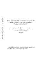
There are different layouts for RGB subpixels, as shown in Figure 1.1. For the stripe configuration,
it is straightforward and easy for fabrication and driving circuit design. However, it has a poor color
mixing performance for the same display area and resolution. For mosaic and delta configurations, their
fabrication and/or driving circuit are more complicated but their image quality is better because of better
color mixing capability. Also, displays with mosaic and delta configurations exhibit faster response times
since the moving distance between the pixels is shorter. Actually, as the resolution gets high enough the
subpixel arrangement becomes less critical. For medium and large displays, the stripe configuration is
typically used. In contrast, for a small-size display which requires high resolution, e.g. video cameras,
one may use the mosaic or delta configuration.
R G B
*
(a) (b) (c)
Figure 1.1 Subpixel layout of an FPD: (a) stripe, (b) mosaic and (c) delta configurations.
Introduction 5
1.3.2 Brightness and color
Luminance and color are two important optical characteristics of an FPD. A display with high luminance
looks dazzling in a dark room. On the other hand, a display with insufficient brightness appears washed
out under high ambient. Typically, the luminance of an FPD should be as bright as (or slightly brighter
than) the real object. Under an indoor lighting environment, a monitor has a luminance of 200–300 cd m
−2
(Section 2.3.6). For a large-screen TV, a higher luminance (500–1000 cd m
−2
) may be needed. An FPD
is used to produce or reproduce colors; hence, how many colors of an FPD and how real the color is
(color fidelity) between an FPD and a real object are two important characteristics of an FPD. Since the
color of an FPD is mixed by (at least) three primary colors, i.e. RGB, more ‘pure’ (saturated) primaries
results in a broader range of the possibly displayed colors, which is called ‘color gamut’ (Section 2.3.4).
One can equally divide the stimuli to the eyes from dark to bright with 2, 4, 8 or more spacings, which
is called ‘gray level’or ‘gray scale’ (Section 2.3.3). For example, an FPD can display 16 million colors
(2
8
× 2
8
× 2
8
≈ 16.8 million) when each RGB subpixel is divided into 8 gray scales.
1.3.3 Contrast ratio
The device contrast ratio (CR) of an FPD is defined as
CR =
L
w
L
b
, (1.1)
where L
w
and L
b
are the luminance at white and black states, respectively. Higher CR means higher on/off
ratio and hence better image quality and higher color saturation. When CR is equal to or less than 1, the
human eye cannot distinguish the on and off colors so that the information content of an FPD is lost or
distorted. For most emissive displays, the off-state luminance is zero. Hence, the contrast ratio is infinity
in a perfectly dark room. However, due to the surface reflection from the ambient, Equation (1.1) should
be modified to
A-CR =
L
w
+L
ar
L
b
+L
ar
, (1.2)
where A-CR is the ambient contrast ratio and L
ar
is the luminance from ambient reflection. A-CR is used
to specify the ambient contrast ratio, to distinguish from the intrinsic ‘device’ contrast ratio as described
in Equation (1.1). From Equation (1.2), as the ambient reflection increases, A-CR decreases sharply. To
keep a good ambient contrast, one can: (1) increase the on-state luminance, and (2) reduce the reflectivity
of the display surface. However, for a very strong ambient, e.g. in sunshine outdoors, luminance from
the direct sun is four orders of magnitude higher than that of an FPD, which severely washes out the
information content of the FPD. Sunlight readability is an important issue especially for mobile displays.
In contrast, an adequate ambient light is required for conventional displays, such as books or newspapers.
A similar situation applies to reflective displays, such as reflective LCDs.
1.3.4 Spatial and temporal characteristics
Uniformity of an FPD means the luminance and color change over a display area. Human eyes are
sensitive to luminance and color differences. For example, a 5 % luminance difference is noticeable
between two adjacent pixels. For a gradual change, human eyes can tolerate up to 20 % luminance
change over the whole display.
Optical characteristics (luminance and colors) may also change at different viewing angles. For
Lambertian emitters, such as CRTs, PDPs and FEDs, viewing angle performances are quite good. The
emission profile of LEDs and OLEDs can be engineered by packaging and layer structure. However,
the viewing angle of LCDs is one of the major issues because LC material is birefringent and crossed
6 Introduction to Flat Panel Displays
polarizers are no longer crossed when viewed at oblique angles. There are several ways to define the view-
ing angle of an FPD. For example, to find the viewing cone with: (1) a luminance threshold; (2) minimum
contrast ratio, say 10:1; or (3) maximum value of color shift. For some cases that contrast ratio is smaller
than 1; this is called ‘gray level inversion’.
Response time is another important metric. If an FPD has a slow response time, one may see blurred
images for fast moving objects. By switching the pixel from ‘off’ to ‘on’ and from ‘on’ to ‘off’, and
calculating the time required from 10 to 90 % and 90 to 10 % luminance levels, one can obtain rise and
fall time, respectively. One may also define the response time from one gray level to another, which is
called the ‘gray-to-gray’ (GTG) response time. Most display scenes contain rich grayscales. Therefore,
GTG response time is more meaningful. For LCDs, this GTG response time can be much longer than the
black-to-white rise and fall time.
3
A TFT is a holding type of active matrix. It is different from the CRT’s
impulse type. Therefore, a motion picture response time
4
is commonly used to define the response time
of a TFT LCD.
After long-term operation, the luminance of an FPD (especially an emissive display) decays. In an
emissive display, if a fixed pattern is lit on for a long period of time before all the pixels are turned on for
the full white screen, one can see nonuniformity of the fixed pattern with a lower brightness, which is
called the ‘residual image’. As mentioned before, the human eye can detect less than 5 % nonuniformity
between two adjacent pixels. Hence the lifetime of an FPD is crucial for static images. An alternative
solution is to use moving pictures, rather than static images, for information display. Then the luminances
of all pixels decay uniformly, since the average on time for all pixels is the same.
1.3.5 Efficiency and power consumption
Power consumption is a key parameter, especially for mobile displays, as it affects battery life. For
displays with wall-plug electrical input, lower power consumption implies lower heat generation, which
means heat dissipation is less serious. Typically, one uses the unit lm W
−1
to describe power efficiency
of an FPD (Section 2.3.6). Lumen (lm) and watt (W) are units for describing light output and electrical
input. A portable display with lower power consumption leads to a longer battery life. For notebooks and
TVs, high optical efficiency also translates into less heat dissipation and a lower electricity bill. Thermal
management in a small-chassis notebook is an important issue.
1.3.6 Flexible displays
An FPD is usually fabricated on thin glass plates. Glass is a kind of rigid substrate. In contrast, conventional
displays are printed on paper, which is flexible. An interesting research topic is to fabricate FPDs on
flexible substrates, as a ‘paper-like’display.
5
Compared to the glass-based FPDs, flexible displays are thin
and lightweight.Also, flexible displays can be fabricated by the roll-to-roll process, which is potentially of
low cost. Substrate selection of flexible FPDs includes ultrathin glass, plastic and stainless steel. Bendable
ultrathin glass substrate is achievable, but the cost is high. Plastic substrate is suitable for flexible displays,
but the highest durable temperature is typically lower than 200
◦
C. Stainless steel substrate is bendable,
and durable for high temperature; however, it is opaque hence not suitable for transmissive displays.
There are many technical bottlenecks for flexible FPDs, such as material selection, fabrication processes,
device configurations, display package and measurement.
1.4 Applications of flat panel displays
The following subsections briefly outline the applications of each technology. Detailed mechanisms are
described in the related chapters.