Medium access control survey kumar
Bạn đang xem bản rút gọn của tài liệu. Xem và tải ngay bản đầy đủ của tài liệu tại đây (576.1 KB, 33 trang )
Medium Access Control protocols for ad hoc
wireless networks: A survey
Sunil Kumar
a,
*
, Vineet S. Raghavan
b
, Jing Deng
c
a
Department of Electrical and Computer Engineering, Clarkson University, Potsdam, NY 13699, United States
b
Digital Television Group, ATI Technologies Inc., Marlborough, MA 01752, United States
c
Department of Computer Science, University of New Orleans, New Orleans, LA 70148, United States
Received 17 October 2003; received in revised form 13 September 2004; accepted 8 October 2004
Available online 2 November 2004
Abstract
Studies of ad hoc wireless networks are a relatively new field gaining more popularity for various new applications.
In these networks, the Medium Access Control (MAC) protocols are responsible for coordinating the access from active
nodes. These protocols are of significant importance since the wireless communication channel is inherently prone to
errors and unique problems such as the hidden-terminal problem, the exposed-terminal problem, and signal fading
effects. Although a lot of research has been conducted on MAC protocols, the various issues involved have mostly been
presented in isolation of each other. We therefore make an attempt to present a comprehensive survey of major
schemes, integrating various related issues and challenges with a view to providing a big-picture outlook to this vast
area. We present a classification of MAC protocols and their brief description, based on their operating principles
and underlying features. In conclusion, we present a brief summary of key ideas and a general direction for future work.
Ó 2004 Elsevier B.V. All rights reserved.
Keywords: Ad hoc networks; Wireless networks; MAC; Medium Access Control; Quality of Service (QoS); MANET
1. Introduction
Back in the 1970s, the Defense Advanced Re-
search Projects Agency (DARPA) was involved
in the development of packet radio netw orks for
use in the battlefields. Around the same time, the
ALOHA [1] project used wireless data broadcast-
ing to create single hop radio networks. This sub-
sequently led to development of the multi-hop
multiple-access Packet Radio Network (PRNET),
which allowed communication coverage over a
wide area. The term multi-hop refers to the fact
that data from the source needs to travel through
several other intermediate nodes before it reaches
the destination. One of the most attractive features
of PRNET was rapid deployment. Also, after
1570-8705/$ - see front matter Ó 2004 Elsevier B.V. All rights reserved.
doi:10.1016/j.adhoc.2004.10.001
*
Corresponding author. Tel.: +1 315 268 6602; fax: +1 315
268 7600.
E-mail address: (S. Kumar).
Ad Hoc Networks 4 (2006) 326–358
www.elsevier.com/locate/adhoc
installation, the whole system was self-initializing
and self-organizin g. The network consisted of mo-
bile radio repeaters, wireless terminals and dedi-
cated mobile stations. Packets were relayed from
one repeater to the other until data reached its
destination.
With the development of technology, devices
have shrunk in size and they now incorporate
more advanced functions. This allows a node to
act as a wireless terminal as well as a repeater
and sti ll be compact enough to be mobile. A self-
organizing and adaptive collection of such devices
connected with wireless links is now referred to as
an Ad Hoc Network. An ad hoc network does not
need any centralized control. The network should
detect any new nodes automatically and induct
them seamlessl y. Conversely, if any node moves
out of the network, the remaining nodes should
automatically reconfigure themselves to adjust to
the new scenario. If nodes are mobile, the network
is termed as a MANET (Mobile Ad hoc NET-
work). The Internet Engineering Task Force
(IETF) has set up a working group named MAN-
ET for encouraging research in this area [2].
Typically, there are two types of architectures in
ad hoc networks: flat and hierarchical [3,6]. Each
node in an ad hoc network is equipped with a
transceiver, an antenna and a power source. The
characteristics of these nodes can vary widely in
terms of size, processing ability, transmission
range and battery power. Some nodes lend them-
selves for use as servers, others as clients and yet
others may be flexible enough to act as both,
depending on the situation. In certain cases, each
node may need to act as a router in order to con-
vey information from one node to another [4,5].
1.1. Applications
Coupled with global roaming capabilities and
seamless integration with existing infrastructure,
if any, ad hoc wireless networks can be used in
many new applications [6,8]. In case of natural
or other disasters, it is possible that existing com-
munication infrastructure is rendered unusable.
In such situations, an ad hoc wireless network fea-
turing wideband capabilities can be set up almost
immediately to provide emergency communication
in the affected region. In mobile computing envi-
ronments, mobile wireless devices that have the
capability to detect the presence of existing net-
works can be used to synchronize data with the
userÕs conventional desktop computers automati-
cally, and download appointment/schedule data.
A user carrying a handheld Personal Digital Assis-
tant (PDA) device can download Context sensitive
data in a shopping mall or museum featuring such
wireless networks and services. The PDA would be
able to detect the presence of the network and con-
nect itself in an ad hoc fashion. Depending on the
userÕs movement, the PDA can poll the network
for relevant information based on its current loca-
tion. For instance, if the user is moving through
the clothing section of the shopping mall, informa-
tion on special deals or pricing can be made avail-
able. Similarly, ad hoc networks can be used in
travel-related and customized household applica-
tions, telemedicine, virtual navigation, etc.
1.2. Important issues
There are several important issues in ad hoc
wireless networks [3,6–8,70]. Most ad hoc wireless
network applications use the Industrial, Sc ientific
and Medical (ISM) band that is free from licensing
formalities. Since wireless is a tightly controlled
medium, it has limited channel bandwidth that is
typically much less than that of wired networks.
Besides, the wireless medium is inherently error
prone. Even though a radio may have sufficient
channel bandwidth, factors such as multiple ac-
cess, signal fading, and noise and interference
can cause the effective throughput in wireless net-
works to be significantly lower. Since wireless
nodes may be mobile, the network topology can
change frequently without any predictable pattern.
Usually the links between nodes would be bi-direc-
tional, but there may be cases when differences in
transmission power give rise to unidirectional links,
which necessitate special treatment by the Medium
Access Control (MAC) protocols. Ad hoc network
nodes must conserve energy as they mostly rely on
batteries as their power source. The security issues
should be considered in the overall network design,
as it is relatively easy to eavesdrop on wireless
transmission. Routing protocols require information
S. Kumar et al. / Ad Hoc Networks 4 (2006) 326–358 327
about the current topology, so that a route from a
source to a destination may be found. However,
the existing routing schemes, such as distance-vec-
tor and link-state based protocols, lead to poor
route convergence and low throughput for dy-
namic topology. Therefore, a new set of routing
schemes is needed in the ad hoc wireless context
[5,8].
MAC layer, sometimes also referred to as a sub-
layer of the ÔData LinkÕ layer, involves the func-
tions and procedures necessary to transfer data
between two or more nodes of the network. It is
the responsibility of the MAC layer to perform
error correction for anomalies occurring in the
physical layer. The layer performs specific activi-
ties for framing, physical addressing, and flow
and error controls. It is responsible for resolving
conflicts among different nodes for channel access.
Since the MAC layer has a direct bearing on how
reliably and efficiently data can be transmitted
between two nodes along the routing path in the
network, it affects the Quality of Service (QoS) of
the network. The design of a MAC protocol should
also address issues caused by mobility of nodes and
an unreliable time varying channel [6–8].
1.3. Need for special MAC protocols
The popular Carrier Sense Multiple Access
(CSMA) [9] MAC scheme and its variations such
as CSMA with Collision Detection (CSMA/CD)
developed for wired networks, cannot be used di-
rectly in the wireless networks, as explained below.
In CSMA-based schemes, the transmitting node
first senses the medium to check whether it is idle
or busy. The node defers its own transmission to
prevent a collision with the existing signal, if the
medium is busy. Otherwise, the node begins to
transmit its data while continuing to sense the
medium. However, collisions occur at receiving
nodes. Since, signal strength in the wireless med-
ium fades in proportion to the square of distance
from the transmitter, the presence of a signal at
the receiver node may not be clearly detected at
other sending terminals, if they are out of range.
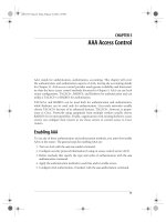
As illustrated in Fig. 1, node B is within the range
of nodes A and C, but A and C are not in each
otherÕs range. Let us consider the case where A is
transmitting to B. Node C, being out of A Õs range,
cannot detect carrier and may therefore send data
to B, thus causing a collision at B. This is referred
to as the Ôhidden-terminal problemÕ, as nodes A and
C are hidden from each other [10,11].
Let us now consider another case where B is
transmitting to A. Since C is within BÕs range, it
senses carrier and decides to defer its own trans-
mission. However, this is unnecessary because
there is no way CÕs transmission can cause any col-
lision at receiver A. This is referred to as the
Ôexposed-terminal problemÕ, since B being exposed
to C caused the latter to needlessly defer its trans-
mission [11]. MAC schemes are designed to over-
come these problems.
The rest of the paper is organized as follows. A
classification of ad hoc network MAC schemes is
given in Section 2. Details of various MAC
schemes in each class are discussed in Sections 3
and 4. The summary and future research directions
are described in Section 5, followed by conclusion
in Section 6.
2. Classification
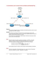
Various MAC schemes developed for wireless
ad hoc networks can be classified as shown in
Fig. 2. In contention-free schemes (e.g., TDMA,
FDMA, CDMA), certain assignments are used
to avoid contentions [6]. Contention based
schemes, on the other hand, are aware of the risk
of collisions of transmitted data. Since conten-
tion-free MAC schemes are more applicable to
Fig. 1. Illustration of the hidden and exposed terminal
problems.
328 S. Kumar et al. / Ad Hoc Networks 4 (2006) 326–358
static networks and/or networks with centralized
control, we shall focus on contention-based MAC
schemes in this survey.
We can view this category as a collection of
Ôrandom accessÕ and Ôdynami c reservation/colli sion
resolutionÕ protocols as shown in Fig. 2(a) [12].In
random access based schemes, such as ALOHA, a
node may access the channel as soon as it is
ready. Naturally, more than one node may trans-
mit at the same time, causing collisions. ALOHA
is more suitable under low system loads with
large number of potential senders and it offers rel-
atively low throu ghput. A variation of ALOHA,
termed ÔSlotted ALOHAÕ, introduces synchronized
(a)
(b)
Fig. 2. Classification of MAC schemes.
S. Kumar et al. / Ad Hoc Networks 4 (2006) 326–358 329
transmission time-slots similar to TDMA. In this
case, nodes can transmit only at the beginning of
a time-slot. The introduction of time slot doubles
the throughput as compared to the pure ALOHA
scheme, with the cost of necessary time synchroni-
zation. The CSMA-based schemes further reduce
the possibility of packet collisions and improve
the throughput.
In order to solve the hidden and exposed termi-
nal problems in CSMA, researchers have come up
with many protocols, which are contention based
but involve some forms of dynamic reservation/
collision resolution. Some schemes use the Re-
quest-To-Send/Clear-To-Send (RTS/CTS) control
packets to prevent collisions, e.g. M ultiple Access
Collision Avoidance (MACA) [13] and MACA
for Wireless LANs (MACAW) [14]. Yet others
use a combination of carrier sensing and control
packets [15,16,23], etc.
As shown in Fig. 2(b), the contention-based
MAC schemes can also be classified as sender-
initiated vs. receiver-initiated, single-channel vs.
multiple-channel, power-aware, directiona l anten-
na based, unidirectional link based and QoS aware
schemes. We briefly discuss these categories in the
following:
One distinguishing factor for MAC protocol s is
whether they rely on the sender initiating the data
transfer, or the receiver requesting the same [6] .As
mentioned above, the dynamic reservation ap-
proach involves the setting up of some sort of a
reservation prior to data transmission. If a node
that wants to send data takes the initiative of set-
ting up this reservation, the protocol is considered
to be a sender-initiated protocol. Most schemes
are sender-initiated. In a receiver-initiated protocol ,
the receiving node polls a potential transmitting
node for data. If the sending node indeed has
some data for the receiver, it is allowed to trans-
mit after being polled. The MACA—By Invitation
(MACA-BI) [17] and Receiver Initiated Busy
Tone Multiple Access (RI-BTMA) [18] are exam-
ples of such schemes. As we shall see later,
MACA-BI is slightly more efficient in terms of
transmit and receive turn around times compared
to MACA.
Another classification is based on the number of
channels used for data transmission. Single chan-
nel protocols set up reservations for transmissions,
and subsequently transmit their data using the
same channel or frequency. Many MAC schemes
use a single channel [1,9,13–15, etc.]. Multiple
channel protocols use more than one channel in
order to coordinate connection sessions among
the transmitter and receiver nodes. The FCC man-
dates that all radios using the ISM band must em-
ploy either DSSS or FHS S schemes. Several MAC
protocols have been developed for using multiple
channels through frequency-hopping techniques,
e.g., Hop-Reservation Multiple Access (HRMA)
scheme [19]. Some others use a special control-
signal on a separate channel for protecting the ac-
tual data that is transmitted on the data channel(s)
[20,47–53].
As mentioned earlier, it becomes important in
the context of low power devices, to have energy
efficient protocols at all layers of the network
model. Much work has already been done for
studying and developing appropriate MAC proto-
cols that are also power aware ([27–36] , etc).
Yet another class of MAC protocols uses direc-
tional antennas [56–64]. The advantage of this
method is that the signals are transmitted only in
one direction. The nodes in other direct ions are
therefore no longer prone to interference or colli-
sion effects, and spatial reuse is faci litated.
Usually the links between nodes are bi-direc-
tional, but there may be cases when differences in
transmission power give rise to unidirectional
links, which necessitate special treatment by the
MAC protocols. Prakash [66] pointed out some
of the issue s to be taken care of in unidirectional
link networks. Several MAC schemes have been
proposed for unidirectional links [10,67–69].
With the growing popularity of ad hoc net-
works, it is reasonable to expect that users will
demand some level of QoS from it, such as end-
to-end delay, available bandwidth, probability of
packet loss, etc. However, the lack of centralized
control, limited bandwidth channels, node mobil-
ity, power or computational constraints and the
error-prone nature of the wireless medium make
it very difficult to provide effective QoS in ad hoc
networks [3,72–74]. Since the MAC layer has a di-
rect bearing on how reliably and efficiently data
can be trans mitted from one node to the next
330 S. Kumar et al. / Ad Hoc Networks 4 (2006) 326–358
along the routing path in the network, it affects the
Quality of Service (QoS) of the ne twork. Several
QoS-aware MAC schemes have been reported in
the literature [86–99].
Note that the above categories are not totally
independent of each other. In fact, a given MAC
protocol may belong to more than one category.
For example, Power Aware Medium Access
Control with Signaling (PAMAS) [27] is a
power-aware protocol that also uses two channels.
Similarly; RI-BTMA is a receiver-initiated MAC
scheme that uses multiple channels.
Several representative MAC schemes for ad hoc
wireless networks are briefly discussed and sum-
marized in the following two sections. For the sake
of convenience in discussion, we have broadly ar-
ranged the schemes in Ônon-QoSÕ and ÔQoS-awareÕ
classes. The non-QoS MAC schemes in Section 3
have been further divided in the following catego-
ries: general, power-aware, multiple channel,
directional antenna-based, and unidirectional
MAC protocols. Similarly, QoS-aware schemes
(in Section 4) have been arranged in a few catego-
ries according to their properties. In the process of
choosing these MAC schemes, we tended to select
those that are more representative in their
category.
3. Review of non-QoS MAC protocols
In particular, we shall discus s several important
contention based MAC schemes in the single chan-
nel, receiver initiated, power-aware, and multiple
channel categories. Due to space limitation, we
will only briefly discuss other categories. However,
it should not mean that these other categories are
less important.
3.1. General MAC protocols
We have mostly included the single channel
protocols in this sub-section. A receiver initiated
MACA-BI scheme is also discussed.
3.1.1. Multiple access collision avoidance (MACA)
The MACA protocol was proposed by Karn to
overcome the hidden and exposed terminal prob-
lems in CSMA family of protocols [13]. MACA
uses two short signaling packets, similar to the
AppleTalk protocol [21].InFig. 1, if node A
wishes to transmit to node B, it first sends an
RTS packet to B, indicating the length of the data
transmission that would later follow. If B receives
this RTS packet, it returns a CTS packet to A that
also contains the expected length of the data to be
transmitted. When A receives the CTS, it immedi-
ately commences transmission of the actual data to
B. The key idea of the MACA scheme is that any
neighboring node that overhears an RTS packet
has to defer its own transmissions until some time
after the associated CTS packet would have fin-
ished, and that any node overhearing a CTS pack-
et would defer for the length of the expecte d data
transmission.
In a hidden terminal scenario (see Fig. 1) as ex-
plained in Section 1, C will not hear the RTS sent
by A, but it would hear the CTS sent by B.
Accordingly, C will defer its transmission during
A Õs data transmission. Similarly, in the exposed
terminal situation, C would hear the RTS sent
by B, but not the CTS sent by A. Therefore C will
consider itself free to transmit during BÕs transmis-
sion. It is apparent that this RTS–CTS exchange
enables nearby nodes to reduce the collisions at
the receiver, not the sender. Collisions can still oc-
cur between different RTS packets, though. If two
RTS packets collide for any reason, each sending
node waits for a randomly chosen interval before
trying again. This process continues until one of
the RTS transmissions elicits the desired CTS from
the receiver.
MACA is effective because RTS and CTS pack-
ets are significantly shorter than the actual data
packets, and therefore collisions among them are
less expensi ve compared to collisions among the
longer data packets. However, the RTS–CTS ap-
proach does not always solve the hidden terminal
problem completely, and collisions can occur when
different nodes send the RTS and the CTS packets.
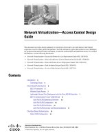
Let us consider an example with four nodes A, B,
C and D in Fig. 3. Node A sends an RTS packet to
B, and B sends a CTS pa cket back to A.AtC,
however, this CTS packet collides with an RTS
packet sent by D. Therefore C has no knowledge
of the subsequent data transmission from A to B.
S. Kumar et al. / Ad Hoc Networks 4 (2006) 326–358 331
While the data packet is being transmitted, D
sends out another RTS because it did not receive
a CTS packet in its first attempt. This time, C re-
plies to D with a CTS packet that collides with
the data packet at B. In fact, when hidden termi-
nals are present and the network traffic is high,
the performance of MACA degenerates to that
of ALOHA [20].
Another weakness of MACA is that it does not
provide any acknowledgment of data transmissions
at the data link layer. If a transmission fails for
any reason, retransmission has to be initiated by
the transport layer. This can cause significant de-
lays in the transmission of data.
In order to overcome some of the weaknesses of
MACA, Bharghavan et al. [14] proposed MACA
for Wireless (MACAW) scheme that uses a five
step RTS–CTS–DS–DATA–ACK exchange. MA-
CAW allow s much faster error recovery at the
data link layer by using the acknowledgment pack-
et (ACK) that is returned from the receiving node
to the sending node as soon as data reception is
completed. The backoff and fairness issues among
active nodes were also investigated. MACAW
achieves significantly higher throughput compared
to MACA. It however does not fully solve the hid-
den and exposed terminal problems [15,20].
The Floor Acquisition Multiple Access (FAMA)
is another MACA based scheme that requires
every transmitting station to acquire control of
the floor (i.e., the wireless channel) before it actu-
ally sends any data packet [15]. Unlike MACA or
MACAW, FAMA requires that collision avoid-
ance should be performed both at the sender as
well as the receiver. In order to Ôacquire the
floorÕ, the sending node sends out an RTS using
either non-persistent packet sensing (NPS) or
non-persistent carrier sensing (NCS). The receiver
responds with a CTS packet, which contains the
address of the sending node. Any station overhear-
ing this CTS packet knows about the station that
has acquired the floor. The CTS packets are re-
peated long enough for the benefit of any hidden
sender that did not register another sending nodeÕs
RTS. The authors recommend the NCS variant for
ad hoc networks since it addresses the hidden ter-
minal problem effectively.
3.1.2. IEEE 802.11 MAC scheme
The IEEE 802.11 specifies two modes of
MAC protocol: distributed coordination function
(DCF) mode (for ad hoc networks) and point
coordination function (PCF) mode (for centrally
coordinated infrastructure-based networks) [22–
25]. The DCF in IEEE 802.11 is based on CSMA
with Collision Avoidance (CSMA/C A), which can
be seen as a combination of the CSMA and
MACA schemes. The protocol uses the RTS–
CTS–DATA–ACK sequence for data transmis-
sion. Not only does the protocol use physical
carrier sensing, it also introduces the novel concept
of virtual carrier sensing. This is implemented in
the form of a Network Allocation Vector (NAV),
which is maintained by every node. The NAV con-
tains a time value that represents the duration up
to which the wireless medium is expected to be
busy because of transmissions by other nodes.
Since every packet contains the duration informa-
tion for the remainder of the message, every node
overhearing a packet continuously updates its own
NAV.
Time slots are divided into multiple frames and
there are several types of inter frame spacing (IFS)
slots. In increasing order of length, they are the
Short IFS (SIF S), Point Coordination Function
IFS (PIFS), DCF IFS (DIFS) and Extended IFS
(EIFS). The node waits for the medium to be free
for a combination of these different times before it
actually transmits. Different types of packets can
require the medium to be free for a different num-
Fig. 3. Illustration of failure of RTS–CTS mechanism in
solving Hidden and Exposed terminal problems.
332 S. Kumar et al. / Ad Hoc Networks 4 (2006) 326–358
ber or type of IFS. For instance, in ad hoc mode, if
the medium is free after a node has waited for
DIFS, it can transmit a queued packet. Otherwise,
if the medium is still busy, a backoff timer is initi-
ated. The initial backoff value of the timer is cho-
sen randomly from between 0 and CW-1 where
CW is the width of the contention window, in
terms of time-slots. After an unsuccessful trans-
mission attempt, another backoff is performed
with a doubled size of CW as decided by binary
exponential backoff (BEB) algorithm. Each time
the medium is idle after DIFS, the timer is decre-
mented. When the timer expires, the packet is
transmitted. After each successful transmission,
another random backoff (known as post-backoff)
is performed by the transmission-completing node.
A control packet such as RTS, CTS or ACK is
transmitted after the medium has been free for
SIFS. Fig. 4 shows the channel access in IEEE
802.11.
IEEE 802.11 DCF is a widely used protocol for
wireless LANs. Many of the MAC schemes dis-
cussed in this paper are based on it. Some other
features of this protocol will be discussed along
with such schemes.
3.1.3. Multiple access collision avoidance-by
invitation (MACA-BI)
In typical sender-initiated protocols, the send-
ing node needs to switch to receive mode (to get
CTS) immediately after transmitting the RTS.
Each such exchange of control packets adds to
turnaround time, reducing the overall throughput.
MACA-BI [17] is a receiver-initiated protocol and
it reduces the number of such control packet ex-
changes. Instead of a sen der waiting to gain access
to the channel, MACA-BI requires a receiver to re-
quest the sender to send the data, by using a
ÔReady-To-ReceiveÕ (RTR) packet instead of the
RTS and the CTS pack ets. Therefore, it is a two-
way exchange (RTR–DATA) as against the
three-way exchange (RTS–CTS–DATA) of
MACA [13].
Since the transmitter cannot send any data be-
fore being asked by the receiver, there has to be
a traffic prediction algorithm built into the receiver
so it can know when to request data from the sen-
der. The efficiency of this algorithm determines the
communication throughput of the system. The
algorithm proposed by the authors piggybacks
the information regarding packet queue length
and data arrival rate at the sender in the data
packet. When the receiver receives this data, it is
able to predict the backlog in the transmitter and
send further RTR packets accordingly. There is a
provision for a transmitter to send an RTS packet
if its input buffer overflows. In such a case, the sys-
tem reverts to MACA.
The MACA-BI scheme works efficiently in net-
works with predictable traffic pattern. However, if
the traffic is bursty, the performance degrades to
that of MACA.
3.1.4. Group allocation multiple access with packet
sensing (GAMA-PS)
GAMA-PS incorporates features of contention
based as well as contention free methods [26]. It di-
vides the wireless channel into a series of cycles.
Immediate access when
medium is idle >= DIFS
Busy Medium
Contention Window
Slot Time
Defer Access
Select Slot and decrement backoff as long
as medium sta
y
s idle
DIFS
DIFS
PIFS
SIFS
Backoff Window
Next Frame
Fig. 4. IEEE 802.11 DCF channel access.
S. Kumar et al. / Ad Hoc Networks 4 (2006) 326–358 333
Every cycle is divided in two parts for contention
and group transmission. Although the group
transmission period is further divided into individ-
ual transmission periods, GAMA-PS does not re-
quire clock or time synchronization among
different member nodes. Nodes wishing to make
a reservation for access to the channel employ
the RTS–CTS exchange. However, a node will
backoff only if it understands an entire packet.
Carrier sensing alone is not sufficient reason for
backing off.
GAMA-PS organizes nodes into transmission
groups, which consist of nodes that have been allo-
cated a transmission period. Every node in the
group is expected to listen in on the channel.
Therefore, there is no need of any centralized con-
trol. Every node in the group is aware of all the
successful RTS–CTS exchanges and by extension,
of any idle transmission periods.
Members of the transmission group take turns
transmitting data, and every node is expected to
send a Begin Transmission Period (BTP) packet
before actual data. The BTP contains the state
of the transmission group, position of the node
within that group and the number of group
members. A member station can transmit up to
a fixed length of data, thereby increasing effi-
ciency. The last member of the transmission
group broadcasts a Transmit Request (TR) pack-
et after it sends its data. Use of the TR shorten s
the maximum length of the contention period by
forcing any station that might contend for group
membership to do so at the start of the conten-
tion period.
GAMA-PS assumes that there are no hidden
terminals. As a result, this scheme may not
work well for mobile ad hoc networks. When
there is not enough traffic in the network,
GAMA-PS behaves almost like CSMA. How-
ever, as the load grows, it starts to mimic
TDMA and allows every node to transmit once
in every cycle.
3.2. Power aware MAC protocols
Since mobile devices are battery powered, it is
crucial to conserve energy and utilize power as effi-
ciently as possible. In fact, the issue of power con-
servation should be considered across all the layers
of the protocol stack. The following principles
may serve as general guidelines for power conser-
vation in MAC protocols [27–30]. First, collisions
are a major cause of expensive retransmissions
and should be avoided as far as possible. Second,
the transceivers should be kept in standby mode
(or switched off) whenever possible as they con-
sume the most energy in active mode. Third , in-
stead of using the maximum power, the
transmitter should switch to a lower power mode
that is sufficient for the destination node to receive
the transmission. Several researchers, including
Goldsmith and Wicker [31], have conducted stud-
ies in this area.
As we mentioned in the context of classifying
MAC protoco ls, some approaches implement
power management by alternating sleep and wake
cycles [27,32–34]. Other approaches, classified as
power control, use a variation in the transmission
power [35,36]. We now present the details of some
selected schemes in both categories.
3.2.1. Power aware medium access control with
signaling (PAMAS)
The basic idea of PAMAS developed by Ragha-
vendra and Singh [27] is that all the RTS–CTS ex-
changes are performed over the signaling channel
and the data transmissions are kept separate over
a data channel. While receiving a data packet,
the destination node starts sending out a busy tone
over the signaling channel. Nodes listen in on the
signaling channel to deduce when it is optimal
for them to power down their transceivers. Every
node makes its own decision whether to power
off or not such that there is no drop in the through-
put. A node powers itself off if it has nothing to
transmit and it realizes that its neighbor is trans-
mitting. A node also powers off if at least one
neighbor is transmitting and another is receiving
at the same time. The authors have developed sev-
eral rules to determine the length of a power-down
state.
The authors also mention briefly some strate-
gies, to use this scheme with other protocols like
FAMA [15]. They have also noted that the use
of ACK and transmission of multiple packets
together will also enhance the performance of
334 S. Kumar et al. / Ad Hoc Networks 4 (2006) 326–358
PAMAS. However, the radio transceiver turn-
around time, which might not be negligible, was
not considered in the PAMAS scheme.
3.2.2. Dynamic power saving mechanism (DPSM)
Jung and Vaidya [32] proposed DPSM based on
the idea of using sleep and wake states for nodes in
order to conserve power. It is a variation of the
IEEE 802.11 scheme, in that it uses dynamically
sized Ad-hoc Traffic Indication Message (ATIM)
windows to achieve longer dozing times for nodes.
The IEEE 802.11 DCF mode has a power sav-
ing mechanism, in which time is divided into bea-
con intervals that are used to synchronize the
nodes [23]. At the beginning of each beacon inter-
val, every node must stay awake for a fixed time
called ATIM window. This window is used to an-
nounce the status of packets ready for transmis-
sion to any receiver nodes. Such announcements
are made through ATIM frames, and they are
acknowledged with ATIM-ACK packets during
the same beacon interval. Fig. 5 illustrates the
mechanism. Earlier work [33] shows that if the size
of the ATIM wi ndow is kept fixed, performance
suffers in terms of throughput and energy
consumption.
In DPSM, each node dynamically and indepen-
dently chooses the length of the ATIM window.
As a result, every node can potentially end up hav-
ing a different sized window. It allows the sender
and receiver nodes to go into sleep state immedi-
ately after they have participated in the transmis-
sion of packets announced in the prior ATIM
frame. Unlike the DCF mechanism, they do not
even have to stay awake for the entire beacon
interval. The length of the ATIM window is in-
creased if some packets queued in the outgoing
buffer are still unsent after the current window ex-
pires. Also, each data packet carries the current
length of the ATIM window and any nodes that
overhear such information may decide to modify
their own window lengths based on the received
information.
DPSM is found to be more effective than IEEE
802.11 DCF in terms of power saving and
throughput. However, IEEE 802.11 and DPSM
are not suitable for multi-hop ad hoc networks
as they assume that the clocks of the nodes are
synchronized and the network is connected. Tseng
et al. [34] have proposed three variations of DPSM
for multi-hop MANETs that use asynchronous
clocks.
3.2.3. Power control medium access control (PCM)
Previous approaches of power control used
alternating sleep and wake states for nodes
[27,32,34]. In PCM [35], the RTS and CTS packets
are sent using the maximum available power,
whereas the data and ACK packets are sent with
the minimum power required to communicate
between the sender and receiver.
The method for determining these lower power
levels, described below, has also been used by ear-
lier researchers in [13,43]. An example scenario is
depicted in Fig. 6. Node D sends the RTS to node
E at a transmit power level P
max
, and also includes
this value in the packet. E measures the actual sig-
nal strength, say P
r
, of the received RTS packet.
A
B
C
ATIM DATA
ATIM window
ATIM window
ATIM-ACK
ACK
ATIM window
Dozing
ATIM window
Next beacon interval
Beacon interval
Fig. 5. Power saving mechanism for DCF: Node A announces a buffered packet for B using an ATIM frame. Node B replies by
sending an ATIM-ACK, and both A and B stay awake during the entire beacon interval. The actual data transmission from A to B is
completed during the beacon interval. Since C does not have any packet to send or receive, it dozes after the ATIM window [32].
S. Kumar et al. / Ad Hoc Networks 4 (2006) 326–358 335
Based on P
max
, P
r
and the noise level at its loca-
tion, E then computes the minimum necessary
power level (say, P
suff
) that would actually be suf-
ficient for use by D. Now, when E responds with
the CTS pa cket using the maximum power it has
available, it includes the value of P
suff
that D sub-
sequently uses for data transmission. G is able to
hear this CTS packet and defers its own transmis-
sions. E also includes the power level that it used
for the transmission in the CTS packet. D then
follows a similar process and calculates the mini-
mum required power level that would get a pack-
et from E to itself. It includes this value in the
data packet so that E can use it for sending the
ACK.
PCM also stipulates that the source node peri-
odically transmits the DATA packet at the maxi-
mum power level, for just enough time so that
nodes in the carrier sensing range, such as A may
sense it. PCM thus achieves energy savings with-
out causing throughput degradation.
The operation of the PCM scheme requires a
rather accurate estimation of received packet sig-
nal strength. Therefore, the dynamics of wireless
signal propagation due to fading and shadowing
effect may degrade its performance. Another
drawback of this scheme is the difficulty in imple-
menting frequent changes in the transmit power
levels.
3.2.4. Power controlled multiple access (PCMA)
PCMA, proposed by Mo nks et al. [36], relies on
controlling transmission power of the send er so
that the intended receiver is just able to decipher
the packet. This helps in avoiding interference with
other neighboring nodes that are not involved in
the packet exchange. PCMA uses two channels,
one for sending out busy tones and the other for
data and other control packets. Power control
mechanism in PCMA has been used for increa sing
channel efficiency through spatial frequency reuse
rather than only increasing battery life. Therefore,
an important issue is for the transmitter and recei-
ver pair to determine the minimum power level
necessary for the receiver to decode the packet,
while distinguishing it from noise/interference.
Also, the receiver has to advertise its noise toler-
ances so that no other potential transmitter will
disrupt its ongoing reception.
In the conventional methods of collision avoid-
ance, a node is either allowed to transmit or not,
depending on the result of carrier sensing. In
PCMA, this method is general ized to a bounded
power model. Before data transmission, the sender
sends a Request Power To Send (RPTS) packet on
the data channel to the receiver. The receiver re-
sponds with an Accept Power To Send (APTS)
packet, also on the data channel. This RPTS-
APTS exchange is used to determine the minimum
transmission power level that will cause a success-
ful packet reception at the receiver. After this ex-
change, the actual data is transmitted and
acknowledged with an ACK packet.
In a separate channel, every receiver sets up a
special busy tone as a periodic pulse. The signal
strength of this busy tone advertises to the other
nodes the additional noise power the receiver node
can tolerate. When a sender monitors the busy
tone channel, it is essentially doing something sim-
ilar to carrier sensing, as in CSMA/CA model.
When a receiver sends out a busy tone pulse, it is
doing something similar to sending out a CTS
packet. The RPTS-APTS exchange is analogous
to the RTS–CTS exchange. The major difference
however is that the RPTS-APTS exchange does
not force other hidden transmitters to backoff.
Collisions are resolved by the use of some appro-
priate backoff strategy.
A
D
E
H
Range of
Data
Range of
ACK
TR for CTS
TR for RTS
CS Zone for
RTS
CS Zone for
CTS
G
Fig. 6. Illustration of power control scheme: (CS) carrier sense
and (TR) transmission range [35].
336 S. Kumar et al. / Ad Hoc Networks 4 (2006) 326–358
The authors claim improvements in aggregate
channel utilization by more than a factor of 2 com-
pared to IEEE 802.11 protocol. Since carrier
sensing while simultaneously transmitting is a
complicated operation, there could be a problem
of the ACK packet being subjected to collision.
This is an issue because the noise level at the
source cannot be updated during data transmis-
sion. This seems to be an open problem with all
schemes that use such power control measures.
Woesner et al. [33] also presented the power
saving techniques for IEEE 802.11 and the High
Performance LAN (HIPERLAN) [46] standards.
Chen et al. [37] developed a distributed algorithm
called Span, wherein every node takes into account
its own power reserve and the advantage to its
neighbors before deciding on staying awake (or
going to sleep) and acting as a coordinator node.
The nodes that are awake take care of routing du-
ties. Sivalingam et al. [29] have identified some of
the ideas that can be used to conserve power at
the MAC layer. They have also performed studies
on some protocols in order to compare their per-
formance vis-a
´
-vis power efficiency. In fact, power
control has also been used for network topology
control in [38–40] and to generate energy efficient
spanning trees for multicasting and broadcasting
in [41,42].
3.3. Multiple channel protocols
A major problem of single shared channel
schemes is that the probability of collision in-
creases with the number of nodes. It is possible
to solve this problem with multi-channel ap-
proaches. As seen in the classification, some mul-
ti-channel schemes use a dedicated channel for
control packets (or signaling) and one separate
channel for data transmissions [9,18,20,27,47].
They set up busy tones on the control channel, al-
beit one with small bandwidth consumption , so
that nodes are aware of ongoing transmissions.
Another approach is to use multiple channels
for data packet transmissions. This ap proach has
the following advantages [52]. First, since the max-
imum throughput of a single channel scheme is
limited by the bandwidth of that channel, using
more channels appropriately can potentially in-
crease the throughput. Second, data transmitted
on different channels does not interfere with each
other, and multiple transmissions can take place
in the same region simultaneously. This leads to
significantly fewer collisions. Third, it is easier to
support QoS by using multiple channels. Schemes
proposed in [19,48–53] employ such an approach.
In general, a multiple data-channel MAC protocol
has to assign different channels to different nodes
in real time. The issue of medium access still needs
to be resolved. This involves deciding, for instance,
the time slots at which a node would get access to a
particular channel. In certain cases, it may be nec-
essary for all the nodes to be synchronized with
each other, whereas in other inst ances, it may be
possible for the nodes to negotiate schedules
among themselves.
We discuss below the details of some of the
multiple channel MAC schemes .
3.3.1. Dual busy tone mul tiple access (DBTMA)
In the schemes based on the exchange of RTS/
CTS dialogue, these control packets themselves are
prone to collisions. Thus, in the presence of hidden
terminals, there remains a risk of subsequent data
packets being destroyed because of collisions. The
DBTMA scheme [20] uses out-of-band signaling to
effectively solve the hidden and the exposed termi-
nal problems. Data transmission is however on the
single shared wireless channel. It builds upon ear-
lier work on the Busy Tone Multiple Access
(BTMA) [9] and the Receiver Initiated-Busy Tone
Multiple Access (RI-BTMA) [18] schemes.
DBTMA decentralizes the responsibility of
managing access to the common medium and does
not require time synchronization among the nodes.
As in several schemes discussed earlier, DBMTA
sends RTS packets on data channel to set up trans-
mission requests. Subs equently, two different busy
tones on a separate narrow channel are used to
protect the transfer of the RTS and data packets.
The sender of the RTS sets up a transmit-busy
tone (BTt). Correspondingly, the receiver sets up
a receive-busy tone (BTr) in order to acknowledge
the RTS, without using any CTS packet.
Any node that senses an existing BTr or BTt
defers from sending its own RTS over the chan-
nel. Therefore, both of these busy tones together
S. Kumar et al. / Ad Hoc Networks 4 (2006) 326–358 337
guarantee protection from collision from other
nodes in the vicinity. Through the use of the BTt
and BTr in conjunction, exposed terminals are
able to initiate data packet transmissions. Also,
hidden terminals can reply to RTS requests as
simultaneous data transmission occurs between
the receiver and sender. The authors claimed a sig-
nificant improvement of 140% over the MACA
protocol under certain scenarios. However, the
DBTMA scheme does not use ACK to acknowl-
edge the received data packets. It also requires
additional hardware complexity.
Yeh and Zhou [47] have recently proposed an
R
TS/OTS/CTS (ROC) scheme for efficiently sup-
porting networks with devices having heteroge-
neous power levels and transmission ranges. This
scheme uses an additional Object To Send (OTS)
control packet. By the use of a separate control
channel and single data channel, the proposed
schemes solved problems due to hidden, exposed,
moving, temporarily deaf and heterogeneous
nodes. However, the authors did not present the
simulation resul ts to support their claim.
3.3.2. Multi channel CSMA MAC protocol
The multi-channel CSMA protocol proposed
by Nasipuri et al. [48] divides the total available
bandwidth (W) into N distinct channels of W/N
bandwidth each. Here N may be lower than the
number of nodes in the network. Also, the chan-
nels may be divided based on either an FDMA
or CDMA. A transmitter would use carrier sensing
to see if the channel it last used is free or not. It
uses the last used channel if found free. Otherwise,
another free channel is chosen at random. If no
free channel is found, the node should backoff
and retry later. Even when traffic load is high
and sufficient channels are not available, chances
of collisions are somewhat reduced since each node
tends to prefer its last used channel instead of sim-
ply choosing a new channel at random.
This protocol has been shown to be more effi-
cient than single channel CSMA schemes. Interest-
ingly, the performance of this scheme is lower than
that of the single channel CSMA scheme at lower
traffic load or when there are only a small number
of active nodes for a long period of time. This is
due to the waste of idling channels. In [50] the pro-
tocol is extended to select the best channel based
on the signal power observed at the sender side.
3.3.3. Hop-reservation multiple access (HRMA)
HRMA [19] is an efficient MAC protocol based
on FHSS radios in the ISM band. Earlier proto-
cols such as [54,55] used frequency-hopping radios
to achieve effective CDMA by requiring the radio
to hop frequencies in the middle of data packets.
HRMA uses time-slotting properties of very-slow
FHSS such that an entire packet is sent in the same
hop. HRMA requires no carrier sensing, employs
a common frequency hopping sequence, and al-
lows a pair of nodes to reserve a frequency hop
(through the use of an RTS–CTS exchange) for
communication without interference from other
nodes.
One of the N available frequencies in the net-
work is reserved specifically for synchronization.
The remaining (N À 1) frequencies are divided into
M = floor ((N À 1)/2) pairs of frequencies. For
each pair, the first frequency is used for Hop Res-
ervation (HR), RTS, CTS and data packets, while
the second frequency is used for ACK packets.
HRMA can be treated as a TDMA scheme, where
each time slot is assigned a specific frequency and
subdivided into four parts—synchronizing, HR,
RTS and CTS periods. Fig. 7 shows an example
of the HRMA frame. During the synchronization
period of every time slot, all idle nodes synchronize
to each other. On the other three periods, they hop
together on the co mmon frequency hops that have
been assigned to the time slots.
A sender-node first sends an RTS packet to the
receiver in the RTS period of the time slot. The re-
ceiver sends a CTS packet to the sender in the CTS
s. slot slot 1 slot 2 slot 3 slot 4
f
0
SYN HR RTS CTS
f
2
f
0
Fig. 7. Structure of HRMA slot and frame [19].
338 S. Kumar et al. / Ad Hoc Networks 4 (2006) 326–358
period of that same time slot. Now, the sender
sends the data on the same frequency (at this time,
the other idle nodes are synchronizing), and then
hops to the acknowledgement frequency on which
the receiver sends an ACK. If the data is large and
requires multiple time slots, the sender indica tes
this in the header of the data packet. The receiver
then sends an HR packet in the HR period of the
next time slot, to extend the reservation of the cur-
rent frequency for the sender and receiver. This
tells the other nodes to skip this frequency in the
hopping sequence.
The authors claim that HRMA achieves signif-
icantly higher throughput than Slotted ALOH A in
FHSS channels. It uses simple half-duplex slow
frequency hopping radios that are commercially
available. It however requires synchronization
among nodes, which is not suitable for multi-hop
networks.
3.3.4. Multi-channel medium access control
(MMAC)
So and Vaidya proposed MMAC [49], which
utilizes multiple channels by switching among
them dynamically. Although the IEEE 802.11 pro-
tocol has inherent support for multiple channels in
DCF mode, it only utilizes one channel at present
[23]. The primary reason is that hosts with a single
half duplex transceiver can only transmit or listen
to one channel at a time.
MMAC is an adaptation to the DCF in order to
use multiple channels. Similar to the DPSM
scheme [32], time is divided into multiple fixed-
time beacon intervals. The beginning of every
interval has a smal l ATIM window. During this
window ATIM packets are exchanged among
nodes so that they can coordinate the assignment
of appropriate channels for use in the subsequent
time slots of that interval. Unlike other multi-
channel protocols (e.g., [51–53]), MMAC needs
only one transceiver. At the beginning of every
beacon interval, every node synchronizes itself to
all other nodes by tuning in to a common synchro-
nization channe l on which ATIM packets are ex-
changed. No data packet trans mission is allowed
during this period of time. Further, every node
maintains a preferred channel list (PCL) that
stores the usage of channels within its transmission
range, and also allows for marking priorities for
those channels.
If a node has a data packet to send, it sends out
an ATIM packet to the recipient that includes sen-
derÕs PCL. The receiver in turn compares the sen-
derÕs PCL with that of its own and selects an
appropriate channel for use. It then responds with
an ATIM-ACK packet and includes the chosen
channel in it. If the chosen channel is acceptable
to the sender, it responds with an ATIM-RES
(Reservation) packet. Any node overhearing an
ATIM-ACK or ATIM-RES packet updates its
own PCL. Subsequently, the sender and receiver
exchange RTS/CTS messages on the selected chan-
nel prior to data exchange. Otherwise, if the cho-
sen channel is not suitable for the sender, it has
to wait till the next beacon interval to try another
channel.
The authors have shown using simulations that
the performance of MMAC is better than IEEE
802.11 and DCA [51] in terms of throughput. Also
it can be easily integrated with IEEE 802.11 PSM
mode while using a simple hardware. However, it
has longer packet delay than DCA. Moreover, it
is not suitable for multi-hop ad hoc networks as
it assumes that the nodes are synchronized. It
should be interesting to study its extension to
multi-hop networks by using the approach pro-
posed by Tseng et al. [34].
3.3.5. Dynamic channel assignme nt with power
control (DCA-PC)
DCA-PC proposed by Tseng et al. [52] is an
extension of their DCA protocol [51] that did
not consider the issue of power control. It com-
bines concepts of power control and multiple
channel med ium access in the context of MAN-
ETs. The hosts are assigned channels dynamically,
as and when they need them. Every node is
equipped with two half-duplex transceivers and
the bandwidth is divided into a control channel
and multiple data channels. One transceiver oper-
ates on the control channel in order to exchange
control packets (using maximum power) for
reserving the data channel, and the other switches
between the data channels for exchanging data and
acknowledgments (with power control). When a
host needs a channel to talk to another, it engages
S. Kumar et al. / Ad Hoc Networks 4 (2006) 326–358 339
in an RTS/CTS/RES exchange, where RES is a
special reservation packet, indicating the appropri-
ate data channel to be used.
Every node keeps a table of power levels to be
used when co mmunicating with any other node.
These power levels are calculated based on the
RTS/CTS exchanges on the control channel. Since
every node is always listening to the control chan-
nel, it can even dynamically update the power val-
ues based on the other control exchanges
happening around it. Every node maintains a list
with channel usage information. In essence this list
tells the node which channel its neighbor is using
and the times of such usage.
DCA-PC has been shown to achieve higher
throughput than DCA. However, it is observed
that when the number of channels is increased be-
yond a point, the effect of power control is less sig-
nificant due to overloading of the control channel
[52]. In summary, DCA-PC is a novel attempt at
solving dynamic channel assignment and power
control issues in an integrated fashion.
3.4. Protocols using directional antennas
MAC protocols for ad hoc networks typically
assume the use of omni-directional antennas,
which transmit radio signals to and receives them
from all directions. These MAC protocols require
all other nodes in the vicinity to remain silent. With
directional antennas, it is possible to achieve higher
gain and restrict the transmission to a particular
direction. Similarly, pac ket reception at a node
with directional antenna is not affected by interfer-
ence from other directions. As a result, it is possible
that two pairs of nodes located in each otherÕs
vicinity communicate simultaneously, depending
on the direction of transmission. This would lead
to better spatial reuse in the other unaffected direc-
tions [56]. Using these antennas, however, is not a
trivial task as the correct direction should be pro-
vided and turned to in real time. Besides, new pro-
tocols would need to be designed for taking
advantage of the new features enabled by direc-
tional antennas because the current protocols
(e.g., IEEE 802.11) cannot benefit from these fea-
tures. Currently, directional antenna hardware is
considerably bulkier and more expensive than
omni-directional antennas of compara ble capabili-
ties. Applications involving large military vehicles
are however suitable candidates for wireless devices
using such antenna systems. The use of higher fre-
quency bands (e.g., ultra wide band transmission)
will reduce the size of directional antennas.
Studies have been undertaken for adapting the
slotted ALOHA scheme for use with packet radio
networks and directional antennas [57]. Similar re-
search on packet radio networks involving multi-
ple and directional antennas has also been
presented in [58–60]. Recently, Ramanathan [61]
has discussed channel-access models, link power
control and directional neighbor discovery, in the
context of beam forming directional antennas. Ef-
fects such as improved connectivity and reduced
latency are also discussed. Bandyopadhyay et al.
[62] suggested a scheme in which every node
dynamically stores some information about its
neighbors and their transmission schedules
through the use of special control packets. This al-
lows a node to steer its antenna appropriately
based on the on-going transmissions in the neigh-
borhood. A method for using the directional
antennas to implement a new form of link-state
based routing is also proposed.
Ko et al. [63] suggested two variations of their
Directional MAC (D-MAC) scheme using direc-
tional antennas. This scheme uses the familiar
RTS/CTS/Data/ACK sequence where only the
RTS packet is sent using a directional antenna.
Every node is assumed to be equipped with several
directional antennas, but only one of them is al-
lowed to transmit at any given time, depending on
the location of the intended receiver. In this scheme,
every node is assumed to be aware of its own loca-
tion as well as the locations of its immediate neigh-
bors. This scheme gives better throughput than
IEEE 802.11 by allowing simultaneous transmis-
sions that are not possible in current MAC schemes.
Based on the IEEE 802.11 protocol , Nasipuri
et al. [64] proposed a relatively simple scheme, in
which every node has multiple antennas. Any node
that has data to send first sends out an RTS in all
directions using every antenna. The intended recei-
ver also sends out the CTS packet in all directions
using all the antennas. The original sender is
now able to discern which antenna picked up the
340 S. Kumar et al. / Ad Hoc Networks 4 (2006) 326–358
strongest CTS signal and can learn the relative
direction of the receiver. The data packet is sent
using the corresponding directional antenna in
the direction of the intended receiver. Thus, the
participating nodes need not know their locat ion
information in advance. Please note that only one
radio transceiver in a node can transmit and receive
at a time. Using simulation the authors have shown
that this scheme can achieve up to 2–3 times better
average throughput than CSMA/CA with RTS/
CTS scheme (using omni-directional antennas).
Choudhury et al. [56] presented a Multi-Hop
RTS MAC (M-MAC) scheme for transmission
on multi-hop paths. Since directional antennas
have a higher gain and transmission range than
omni-directional antennas, it is possible for a node
to communicate directly with another node that is
far away. M-MAC therefore uses multiple hops to
send RTS packets to establish links between dis-
tant nodes, but the subsequent CTS, data and
ACK packets are sent in a single hop. Simulation
results indicate that this protocol can achieve bet-
ter throughput and end-to-end delay than the basic
IEEE 802.11 [23] and the D-MAC [63] schemes
presented earlier. The authors however note that
the performance also depends on the topo logy
configuration and flow patterns in the system.
The use of directional antennas can introduce
three new problems: new kinds of hidden termi-
nals, higher directional interference and deafness
[56]. These problems depend on the topology and
flow patterns. For example, the deafness is a prob-
lem if routes of two flows share a common link.
Similarly, nodes that are in a straight line witness
higher directional interference. The performance
of these schemes will degrade with node mobility.
Some of the current protocols (e.g., [63,64]) inac-
curately assume that the gain of direct ional anten-
na is the same as that of omni-directional antenna.
Similarly, none of them considers the effect of
transmit power control, use of multiple channels
and support for real-time traffic.
3.5. Unidirectional MAC protocols
When low-power and battery-operated nodes
coexist with more powerful nodes tethered to
power sources in ad hoc networks, disparities in
the transmission powers and asymmetric links be-
tween nodes are introduced. Such a network is
therefore heterogeneous in terms of power levels.
This gives rise to situations where a node A is able
to transmit to another node B, but B Õs transmis-
sion may not reach A. Recently, some schemes
have been proposed that control the transmission
range of individual node(s) to maintain optimum
network topology [38,40,65]. As a result, there
might be unidirectional links in these networks.
Several studies have been presented on unidirec-
tional MAC. Prakash [66] pointed out some of the
issues to be taken care of in unidirectional link net-
works. In a network of devices having heteroge-
neous power levels, when a low power node tries
to reserve the channel for data transmission, it
may not be heard due to highe r power nodes that
are close enough to disrupt its data exchange. As a
result, a successful RTS–CTS exchange does not
guarantee successful transmission of data. Fur-
thermore, it is important to ensure that the MAC
protocol does not favor certain higher power
nodes. In order to overcome this problem, Poojary
et al. [10] proposed a scheme to extend the reach of
RTS/CTS exchange information in the IEEE
802.11 protocol. This ensures that all hidden high-
er power nodes that could otherwise interfere with
the subsequent DATA transmission are made
aware of the reservation of the channel. Bao et
al. [67] proposed a set of collision-free channel ac-
cess schemes, known as PANAMA, for ad hoc
networks with unidirectional links. In each conten-
tion slot, one or multiple winners are elected deter-
ministically to access the channel.
Agarwal et al. [68] summarized the problems
caused by unidirectional links in ad hoc wireless
networks and presented some modifications of
MAC and routing protocols. Ramasubramanian
[69] presented a Sub Routing Layer (SRL) as a
bidirectional abstraction over unidirectional links
in lower layers. SRL uses different reverse links
as the abstract reverse link to routing layer.
4. QoS-aware MAC protocols
With the growing popularity of ad hoc
networks, it is reasonable to expect that users will
S. Kumar et al. / Ad Hoc Networks 4 (2006) 326–358 341
demand some level of QoS from them. Some of the
QoS related parameters that may be quantified are
end-to-end delay, available bandwidth, probability
of packet loss, etc. However, the lack of central-
ized control, limited bandwidth, error-prone wire-
less channels, node mobility, and power or
computational constraints makes it very difficult
to provide effective QoS in such networks [3,72–
74].
When the nodes join or leave an ad hoc wireless
network at random, periodic topology updates are
required so that every node is aware of the current
network configuration. In case the topology of the
network changes so rapidly that the routine up-
dates are unable to cope up with the same, the net-
work is not combinatorially stable and it may not
be possible to guarantee certain levels of QoS.
However, if such guarantees are maintained
regardless of the changes in topology, the network
is said to be ÔQoS-robustÕ. Otherwise, if the guaran-
tees are maintained between any two consecutive
updates to the topology, the network is said to
be ÔQoS-preservingÕ [3]. The use of priority to real-
ize QoS is known a s Ôprioritized QoSÕ. Prioritized
QoS lets the applications specify a higher priority
for accessing network resources than other appli-
cations. A Ôparameterized QoS Õ involves reserving
resources for the end-to-end path of the applica-
tion data stream. A new stream is not admitted
if enough bandwidth is not available to support
it. This ensures that the already admitted flows re-
main unaffected. In certain situations, the concept
of soft or dynamic QoS may be rather useful. In
soft-QoS [75], after the initial connection is set
up, there can be brief periods of time when there
is a disruption in providing the pre-decided QoS
guarantees. In dynam ic-QoS [76], a resource reser-
vation request specifies a range of values (i.e., the
minimum level of service that the applications
are willing to accept and the maximum level of ser-
vice they are able to utilize), and the network
makes a commitment to provide service at a spec-
ified point within this range. In such a case, alloca-
tion of resources needs to be dynamically adjusted
across all layers of the network. Treating the reser-
vations as ranges provides the flexibility needed for
operation in a dynamic ad hoc network environ-
ment. Real-time consumer applications such as
streaming audio/video require a reserved share of
the channel capacity over relatively long durations
so that QoS requirements are met. However, strin-
gent delivery guarantees, particularly on short
time scales, ne ed not always be fulfilled for such
applications. Therefore, these applications can be
satisfied by soft or dynamic QoS. Other applica-
tions such as inter-vehicle communication for
safety require guaranteed delivery of short bursts
of data with a bounded delay. These applications
will require parameterized QoS. In fact, maintain-
ing QoS guarantees for delay sensitive traffic is
quite difficult in MAN ETs because obtaining a
consistent network-wide distributed snapshot of
the state of the queues and the channel at individ-
ual nodes at any given instant is an intractable
problem.
The issues affecting support for QoS in ad hoc
networks are briefly discussed below, followed by
brief explanation of selected protocols.
4.1. Issues affecting QoS
Several issues, such as the service model, rout-
ing strategies, admission control, resource reserva-
tion, signaling techniques, and MAC protocols
need to be considered in the context of providing
QoS in ad hoc wireless networks. In fact, every
layer of the network has to be made QoS aware be-
cause only when all the factors are considered to-
gether in the overall scenario can effective QoS
be provided for the end-user application. We
briefly discuss below the important issues across
different layers.
A QoS service model specifies an overall archi-
tectural framework, within which certain types of
services can be provided in the network. Some of
the prominent service models suggested for ad
hoc networks are: flexible quality of service model
for MANETs (FQMM) [77], cross layer service
model [78], and stateless model for wireless ad
hoc networks (SWAN) [79].
Signaling is used in order to negotiate, reserve,
maintain and free up resources, and is one of the
most complicated aspects of the network. It should
be performed reliably (including topology
changes) with minimum overhead. Out-of-band
and in-band signaling are two commonly used
342 S. Kumar et al. / Ad Hoc Networks 4 (2006) 326–358
approaches. INSIGNIA [80] and Integrated Mo-
bile Ad Hoc QoS (iMAQ) framew ork [81] are
examples of signaling schemes proposed in the
literature.
If the application needs to be guaranteed a cer-
tain minimum bandwidth or end-to-end delay, the
routing scheme should also be QoS aware. Not
only does the route have to be valid at the time
the data is to be transported, but also all the nodes
along that route need to have sufficient resources
in order to support the QoS requirement of the
data flow and the application. For extensive survey
of routing techniques, the reader is referred to
[3,5,72,82]. Once a potential route is established,
it is necessary to reserve and alloc ate the required
resources in all the nodes of that route so that the
demands of the application can be met. The admis-
sion control becomes important in this context.
QoS supporting components at upper layers as-
sume the existence of a QoS-aware MAC protocol,
which takes care of medium contention, supports
reliable unicast communication, and provides re-
source reservation for rt traffic in a distributed
environment. The MAC protocols are therefore
very important for QoS support, since they have
a direct bearing on how reliably and efficiently
data can be transmitted from one node to the next
along any path in the network. The MAC protocol
should address issues caused by node mobility and
unreliable time-varying channel.
4.2. Review of selected QoS-aware MAC protocols
In ad hoc networks, MAC protocols aim to
solve the problem of contention by addressing
the issues of hidden or exposed terminals. For
real-time applications requiring certain level of
QoS, the MAC layer protocol should also support
resource reservation and real time (rt) traffic.
MAC is a lower level function and needs to be clo-
sely integrated with upper layers such as the net-
work layer for routing. Since centralized control
is not available, it is difficult to maintain informa-
tion about connections and reservations.
There are two ways to avoid the use of a central-
ized coordinator node in QoS-aware MAC
schemes. The first approach involves synchronous
schemes like Cluster TDMA [83,84], Cluster Token
[85], and Soft Reservation Multiple Access with
Priority Assignment (SRMA/PA) [86].InCluster
TDMA, the nodes are organized into clusters, and
each cluster has a cluster head that is responsible
for coordinat ing the activities of the nodes under
its purview. Each cluster uses a different DS-Spread
Spectrum code. A common, globally synchronous
slotted TDM frame is defined among clusters. Slots
can be reserved by rt traffic and free slots are used
by non-real-time (nrt) data. The rt traffic handling
performance of the scheme is very good. However,
time synchronization is a resource intensive process
and should ideally be avoided in ad hoc networks.
Similarly, the implementation of multiple codes
and associated power control is non-trivial. The
merits of such TDMA schemes have been discussed
in [7].InCluster Token scheme, the TDM access
scheme is replaced by an implicit token scheme
within each cluster. Also, no synchronization is re-
quired across different clusters.
The other option is to use asynchronous ap-
proaches that do not require global time synchro-
nization and therefore are more suitable for ad hoc
networks. IEEE 802.11 DCF is a widely used asyn-
chronous protocol that uses a best effort delivery
model [22–25]. It does not support rt traffic as its
random backoff mechanism cannot provide deter-
ministic upper bounds on channel access delays. A
number of QoS-a ware MAC schemes have been
proposed in the past few years and most of them
are more or less based on the IEEE 802.11 DCF.
No formal classification exists in the literature to
group these schemes. We have attempted to clas-
sify below these schemes according to their major
features: i. some schemes, such as real-time MAC
[87], DCF with priority classes [88] and enhanced
DCF (EDCF) [89–91], use shorter inter-frame
spacing and backoff contention values to meet
the delay and bandwidth requirements of rt traffic.
These schemes are relatively straightforward
extensions of IEEE 802.11 DCF and can be over-
laid on this protocol . ii. The black burst (BB ) con-
tention [92,93], elimination by sieving (ES-DCF)
and dead line bursting (DB-DCF) [94,95] schemes
use a shorter inter-frame spacing and a different
approach than the backoff window for chan-
nel contention to support bounded time delay of
rt traffic. iii. Instead of directly manipulating
S. Kumar et al. / Ad Hoc Networks 4 (2006) 326–358 343
inter-frame spacing and contention window, an-
other group of schemes uses reserved time slots
at nodes to provide bounded delay and required
bandwidth for the rt traffic. The nrt data traffic is
treated exactly as in IEEE 802.11. Examples of this
class of schemes are: MACA/PR [96], asynchro-
nous QoS enabled multi-hop MAC [97] and dy-
namic bandwidth allocation/sharing/extension
(DBASE) protocol [98]. iv. The above classes of
schemes may not guarantee a fair proportion of
channel to different flows. Therefore, some
researchers have proposed MAC schemes (e.g.,
distributed fair scheduling [99]) to pro vide a rea-
sonably fair channel allocation to different flows
(often according to their priority).
It should be pointed out that the schemes of dif-
ferent classes often have some common features.
We discuss below salient features of major schemes
in each category.
4.2.1. Real-time MAC (RT-MAC)
In IEEE 802.11 protocol, packets that have
missed their deadlines are still retransmitted, even
though they are not useful any more. This causes
bandwidth and resources to be wasted. Baldwin
et al. [87] proposed a variation of the IE EE
802.11 protocol called RT-MAC that supports rt
traffic by avoiding packet collisions and the trans-
mission of alrea dy expired packets. To achieve this,
RT-MAC scheme uses a packet transmission dead-
line and an Ôenhanced collision avoidanceÕ scheme
to determine the transmission stationÕs next backoff
value. When an rt packet is queued for transmis-
sion, a timestamp is recorded locally in the node
indicating the time by when the packet should be
transmitted. The sending node checks whether a
packet has expired at three points: before sending
the packet, when its backoff timer expires and when
a trans mission goes unacknowledged. An expired
packet is immediately dropped from the transmis-
sion queue. When the packet is actually about to
be sent out, the sending node chooses the next
backoff value and records it in the packet header.
Any node that overhears this packet then ensures
that it chooses a different backoff value. This elim-
inates the possibility of collision. The range of val-
ues (i.e., contention window, CW) from which the
backoff value is chosen, is made a function of the
number of nodes in the system. Therefore, the
number of nodes should be known or at least esti-
mated in this scheme.
RT-MAC scheme has been shown to achieve
drastic reductions in mean packet delay, missed
deadlines, and packet collisions as compared to
IEEE 802.11. However, the contention window
may typically become quite large in a network with
large number of nodes. This will result in wasted
bandwidth when the network load is light.
4.2.2. DCF with priority classes
Deng et al. [88] proposed another variation of
the IEEE 802.11 protocol (henceforth called
DCF-PC) that supports priority based access for
different classes of data. The basic idea is to use
a combination of shorter IFS or waiting times
and shorter backoff time values (i.e., maximum
allowable size of contention window) for higher
priority data (i.e., rt traffic). As already mentioned,
some different IFS intervals specified in the IEEE
802.11 protocol are SIFS, PIFS and DIFS [23–
25]. While normal nodes wait for the channel to re-
main idle after DIFS interval before they transmit
data, a higher priority node waits for only PIFS.
However, if the chosen backoff value happens to
be longer, the higher priority node can still lose
out to another node that has a larger IFS but a
shorter random backoff value. In order to solve
this problem, the authors have proposed two dif-
ferent formulae for generating the random backoff
values so that the higher priority nodes are as-
signed shorte r backoff time.
Using simulations, the authors have demon-
strated that this scheme has better performance
than 802.11 DCF, in terms of throughput, access
delay and frame loss probability for higher priority
(rt) traffic. It can support more than two traffic pri-
orities. However, this scheme lacks the ability to
provide deterministic delay bounds for rt traffic.
Moreover, normal data traffic suffers higher delay
due to a longer backoff time even when no higher
priority node is transmitting. Channel bandwidth
is also wasted in such cases.
4.2.3. Enhanced DCF
IEEE 802.11 DCF is designed to provide a
channel access with equal probabilities to all the
344 S. Kumar et al. / Ad Hoc Networks 4 (2006) 326–358
contending nodes in a distributed manner. EDCF
enhances the DCF protocol to provide differenti-
ated channel access according to the frame
priorities. It has been developed as a part of the
hybrid coordination function (HCF) of IEEE
802.11e [89–91]. We discuss below its working
principle, independent of the details of IEEE
802.11e HCF.
Each data frame is assigned a traffic class (TC)
in the MAC header, based on its priority as
determined in the higher layers. During the con-
tention process, EDCF uses AIFS[TC], CW
min
[TC] and CW
max
[TC] instead of DIFS, CW
min
and CW
max
of the DCF, respectively, for a frame
belonging to a particular TC. Here AIFS (Arbi-
tration Inter Frame Space) duration is at least
DIFS, and can be enlarged individually for each
TC. The CW
min
of the backoff mechanism is set
differently for different priority classes. EDCF
thus combines two measures to provide service
differentiation. Fig. 8 illustrates the EDCF chan-
nel access.
Based on the analysis of delay incurred by IEEE
802.11 DCF, Veres et al. [75] proposed a fully dis-
tributed Virtual MAC (VMAC) scheme that sup-
ports service differentiation, radio monitoring,
and admission control for delay-sensitive and
best-effort traffic. VMAC passively monitors the
radio channel and estimates locally achievable ser-
vice levels. It also estimates key MAC-level QoS
statistics, such as delay, delay variation, packet
collision, and packet loss.
4.2.4. Black burst (BB) contention
Sobrinho and Krishnakumar [92,93] introduced
BB contention scheme in. This scheme is distrib-
uted, can be overlaid on the IEEE 802.11 standard
and relies on carrier sensing. The scheme operates
as follows: Normal data nodes use a longer inter-
frame spacing than rt nodes. This automatically
biases the system in favor of the rt nodes. Instead
of sending their packets when the channel becomes
idle for a predetermined amount of time, rt nodes
jam the channel with pulses of energy (which are
termed the black bursts) whose length is propor-
tional to the contention delay experienced by the
node. This delay is measured from the instant an
attempt is made to access the channel until the
BB transmission is started.
To uniquely identify all the BB pulses sent by
different rt nodes, they all differ in length by at
least one black slot. Follow ing each BB transmis-
sion, a node senses the channel for an observation
period to determine whether its own BB was the
longest or not. If so, the node goes ahead with
its data transmission. Otherwise it has to wait for
the channel to be idle before it can send another
BB. In essence, the scheme seems to achieve a dy-
namic TDM transmission structure without expli-
cit slot assignments or synchronization. It
guarantees that rt packets are transmitted without
collisions and with a higher priority over others. It
has also been shown that BB contention enforces a
round robin discipline among rt nodes (if there is
more than one) and achieves bounded rt delays.
Immediate access when
medium is idle >= AIFS[TC] +
Slot Time
Busy Medium
Contention Window from
[1, CW[TC]+1]
Slot Time
Defer Access
Select Slot and decrement backoff as long
as medium sta
y
s idle
AIFS[TC]
+ Slot Time
DIFS
PIFS
SIFS
Backoff Window
Next Frame
Fig. 8. The EDCF channel access scheme.
S. Kumar et al. / Ad Hoc Networks 4 (2006) 326–358 345
The BB contention scheme thus provides some
QoS guarantees to rt multimedia traffic as com-
pared to simple carrier sense networks. Applica-
tions considered are those like voice and video
that require more or less periodic access to the
channel during long periods of time denominated
sessions. One of the main considerations in such
applications is the end-to-end delay. This trans-
lates to requiring a bounded packet delay at the
data link layer. However, this scheme does not
consider hidden terminal problem.
4.2.5. Elimination by sieving (ES-DCF) and
deadline bursting (DB-DCF)
Pal et al. [94,95] proposed two variants of the
IEEE 802.11 DCF that offer guaranteed time
bound delivery for rt traffic, by using deterministic
collision resolution algorithms. Interestingly, they
also employ black burst features.
The ES-DCF has three phases of operation—
elimination, channel acquisition and collision reso-
lution. In elimination phase, every node is assigned
a grade based on the deadlines and priority of its
packets as in [88]. A closer deadline results in a
lower numerical grade, which translates to lower
than DIFS channel-free wait times. Therefore,
the grade of the packet improves if it remains in
the queue for a longer time. In the channel acqui-
sition phase, the node transmits RTS packet to ini-
tiate the channel acquisition, when the channel ha s
been free for the requisite amount of time, as
decided by the grade of its data packet. If it re-
ceives a CTS packet in return, the channel is con-
sidered acquired successfully. Otherwise, the third
phase of collision resolution is initiated by sending
out a BB (as in [92,93]). The length of the BB cor-
responds to the node identification (Id) num ber.
Higher Id numbers are given to the nodes that gen-
erate a lot of rt data. The node that sends out the
longest burst accesses the channel at the subse-
quent attempt.
In the DB-DCF, the first phase is for BB con-
tention wherein the lengths of the BB packets are
proportional to the urgency (i.e., relative dead-
lines) of the rt packet. This is followed by phases
for channel acquisition and collision resolution,
which are similar to the corresponding phases in
ES-DCF.
Both schemes assign channel-free wait time
longer than DIFS for nrt nodes, such that these
nodes are allowed to transmit only when the other
rt nodes have no data waiting to be sent. However,
the results of the simulations carried out by the
authors indicate that ES-DCF is more useful when
hard rt traffic is involved, and DB-DCF performs
better in the case of nodes with soft rt packets. Due
to the use of BB and lon ger (than DIFS) channel-
free wait time for nrt traffic, these schemes cannot
be directly overlaid on any existing IEEE 802.11
DCF implementation.
4.2.6. Multiple access collision avoidance with
piggyback reservations (MACA/PR)
Lin and Gerla [96] proposed MACA/PR archi-
tecture to provide efficient rt multimedia support
over ad hoc networks. MACA/PR is an extension
of IEEE 802.11 [23–25] and FAMA [15]. The
architecture includes a MAC protocol, a reserva-
tion protoco l for setting up rt connections and a
QoS aware routing scheme. We will discuss only
the MAC protocol here.
In MACA/PR, nodes maintain a special reser-
vation table that tells them when a packet is due
to be transmitted. The first data packet in an rt
data stream sets up reservations along the entire
path by using the standard RTS–CTS approach.
Both these control packets contain the expected
length of the data packet. As soon as the first
packet makes such a reservation on a link, a trans-
mission slot is allocated at the sender and the next
receiver node at appropriate time intervals (usually
in the next time cycle) for the subsequent packet of
that stream. The sender also piggybacks the reser-
vation information for the subsequent data packet
in the current data packet. The receiver notes this
reservation in its reservation table, and also con-
firms this through the ACK packet. Neigh boring
nodes overhearing the data and ACK packets, be-
come aware of the subsequent packet transmission
schedule, and back off accordingly. The ACK only
serves to renew the reservation, as the data packet
is not retransmitted even if the ACK is lost due to
collision. If the sender consecutively fails to receive
ACK N times, it assumes that the link cannot sat-
isfy the bandwidth requirement and notifies the
upper layer (i.e., QoS routing protocol). Since
346 S. Kumar et al. / Ad Hoc Networks 4 (2006) 326–358
there is no RTS–CTS exchange after the first data
packet, collision prevention of rt packets is
through the use of the reservation tables. For nrt
data packet, MACA/PR uses IEEE 802.11 DCF.
Using simulations, the authors have demon-
strated that this asynchronous scheme is able to
achieve a lower end-to-en d delay than other
schemes that require time synchronization such
as Cluster Token and Cluster TDMA. However,
since the cluster based schemes use code separa-
tion, they can achieve higher aggregate throughput
efficiency. Another reason for lower throughput
achieved by MACA/PR is that multiple reserva-
tion tables need to be kept current at all times so
that the sending node can consult them before
transmission. This introduces an overhead on the
network as the tables are exchanged frequently
among neighbors.
4.2.7. Asynchron ous QoS enabled multi-hop MAC
Ying et al. [97] proposed an asynchronous pro-
tocol based on the IEEE 802.11 DCF, that sup-
ports constant bit-rate (CBR) and variable bit
rate (VBR) rt traffic, and regula r nrt datagram
traffic. In the case of an nrt data transmission,
the regular RTS–CTS–DATA–ACK sequence is
employed between the sender and the receiver.
The ack nowledgments sent in response to nrt and
rt packets are called D-ACK and R-ACK, respec-
tively. Similarly, the nrt and rt data packets are
termed as D-PKT and R-PKT, respectively. In
the case of rt traffic, though, there is no RTS–
CTS exchange for the data packets sent after the
first R-PKT (similar to the MACA/PR scheme
[96]). In other words, the R-ACK packet reserves
the trans mission slot for the next rt data packet.
The scheme requires every node to maintain two
reservation table s, Rx RT and Tx RT. The former
(latter) informs the node when neighbors expect
incoming (to transmit) rt traffic. These estimates
are recorded in the corresponding tables based
on the overhearing of R-PKT and R-ACK pack-
ets. In essence, before sending any RTS, nodes
look for a common free slot based on the entries
in the reservation tables so as not to interfere with
rt transmissions already in the queue in the neigh-
borhood. Similarly, if a node receives an RTS, it
performs the same checks before responding with
a CTS packet. After a successful RTS–CTS ex-
change, data is sent out, and an ACK is expected.
If an ACK is missed, the node starts to backoff
(using BEB) and uses the IEEE 802.11 contention
windows for the same.
This scheme allows for bounded delays in rt
traffic but depends on the overhearing of R-PKT
and R-ACK packets within each nodeÕs transmis-
sion range to avoid hidden node problem. Both
the receiver and transmitter nodes check their
own tables, thereby eliminating the overhead of
exchanging table information. Using simulations,
the authors have demonstrated that this scheme
achieves lower delays for rt traffic than BB Con-
tention, MACA/PR and DFS [99] schemes. The
packet loss rates are also relatively small.
Sheu et al. [98] have proposed the Dynamic
Bandwidth Allocation/Sharing/Extension (DBASE)
protocol that also uses a reservation table for sup-
porting rt traffic. A unique feature of this scheme is
that bandwidth allocation can change dynamically
over time, which allows effici ent support of CBR
as well as VBR traffic. The scheme achieves very
high throughput and low packet loss probability
for rt-packets even at heavy traffic load, and out-
performs the IEEE 802.11 DCF [23–25] and DFS
[99] schemes. DBASE, however, assumes that all
the nodes can hear one another and it may be dif-
ficult to extend it to the (multi-hop) ad hoc net-
works with hidden terminals. Overall, DBASE is
a quite different scheme than the other two (previ-
ously discussed) reservation based schemes.
4.2.8. Distributed fair scheduling (DFS)
Vaidya et al. [99] proposed the DFS scheme to
ensure that different flows sharing a common wire-
less channel are assigned appropriate bandwidth
corresponding to their weights or priorities. DFS
is derived from the IEEE 802.11 DCF and requires
no central coordinator to regulate access to the
medium. The fundamental idea of DFS is that
each packet is associated with start and finish time-
stamps. A higher priority packet is assigned a
smaller Ôfinish-tagÕ and shorter backoff periods.
This approach ensures that any flow that has
packets of higher priority will consistently have
shorter backoff times, thereby achieving a higher
throughput.
S. Kumar et al. / Ad Hoc Networks 4 (2006) 326–358 347
In DFS, the start and finish times for packets
are calculated on the basis of the Self-Clocked Fair
Queuing (SCFQ) algorithm proposed by Golestani
[100]. Following the idea of SCFQ, every node also
maintains a local virtual clock. DFS does not,
however, REMOVE short-term unfairness in cer-
tain cases. The authors observe that the use of col-
lision resolution schemes such as those proposed in
[101] can resolve this anomaly. In order to calcu-
late backoff intervals, the authors have proposed
two alternate approaches: linear mapping and
exponential mapping. A disadvantage of the linear
mapping scheme is that if many packet flows have
low priorities, all of them are assigned large back-
off intervals. As a result, the system remains idle
for long periods of time. The exponential mapping
approach is proposed as one solution to this
problem.
Using simulations, the authors have shown that
DFS obtains a higher throughput than IEEE
802.11. Also, they have verified that use of expo-
nential mapping technique for calculating backoff
intervals leads to higher throughput than linear
mapping. However, the DFS does not consider
the hidden terminal problem and delay bound of
rt packets [98]. Nandagopal et al. [102] have also
proposed a general analytical framework for mod-
eling the fairness.
5. Summary and future directions
Due to space constraints and the large number
of MAC schemes reviewed in this paper, it is diffi-
cult to compare their quantitative performance.
We briefly discuss below qualitative performance
of some of these schemes.
The CSMA based MAC schemes are not suit-
able in ad hoc networks due to multi-hop trans-
mission and hidden/exposed terminal problems.
The MACA scheme [13] was proposed to solve
these problems with the help of two relatively
short RTS/CTS control packets. The MACAW
scheme [14] adds an ACK packet to the transmis-
sion sequence, providing quicker response to data
packet loss at the MAC layer. The MACAW
scheme also includes techniques to solve the con-
gestion and unfairness problems at the MAC
layer. Although schemes like MACA and MA-
CAW are based on the RTS–CTS dialog and
abandon the carrier sensing mechanism in order
to reduce performance degradation caused by hid-
den terminals, they are only partially successful,
since the control packets are themselves subject
to collisions .
A combination of control packets (e.g., RTS/
CTS/ACK) and carrier sensing (i.e., CSMA) has
been found to reduce the probability of collisions
caused by hidden terminals. Such a strategy has
been used by FAMA -NCS [15] with a mechan ism
to provide ‘‘CTS dominance’’. This solves the hid-
den terminal problem since the data packets can
never collide with CTS packets. The exposed
terminal problem is still unsolved, though. Similar
to the FAMA scheme, the IEEE 802.11 DC F stan-
dard combines the CSMA and the RTS/CTS
message exchange. While IEEE 802.11 DCF works
well in wireless LAN environment, it is not partic-
ularly suitable for multi-hop ad hoc networks with
mobile nodes [71,104].
In spite of the use of RTS/CTS/ACK and
NAV in IEEE 802.11, some packets are still vul-
nerable to collisions as explained below. The
transmission range of a node in which it can suc-
cessfully decode the packet is determined by the
received signal strength. Let RX_Th and CS_Th
denote the minimum received signal power for
receiving a valid packet and sensing a carrier,
respectively. The received signal is discarded as
noise if its strength is lower than CS_Th. If the re-
ceived signal strength is in between RX_Th and
CS_Th, the node cannot decode the packet but
can sense the transmission. This is referred to as
interference range. A node that is out of interfer-
ence range of receiver (sender) but is within the
interference range of sender (receiver) cannot
sense ACK (data packet). As a result, the ACK
and data packets are vulnerable to collisions from
these nodes. Collisions in ACK packets are partic-
ularly troublesome as their loss results in retrans-
mission of long data packets. Extended IFS
(EIFS) is used in IEEE 802.11 DCF to prevent
collisions with ACK receptions at sender
[35,104]. However, most of the other MAC
schemes consider that the transmission range is
equal to the interference range.
348 S. Kumar et al. / Ad Hoc Networks 4 (2006) 326–358
Due to the use of BEB algorithm in IEEE
802.11 DCF, the contention window size quickly
increases for the nodes whose data suffers colli-
sions. On the other hand, the contention window
is set to the minimum value CW
min
for each new
packet even when the previous packet was not
delivered successfully and the network area is
congested. This contention and backoff strategy
is unfair to the already existing nodes that are
backing off due to collisions, especially under
the heavy traffic conditions. Bhargavan et al.
[14] attempted to improve the situation by using
the multiplicative increase and linear decrease
(MILD) algorithm in MACAW. This scheme
however reduces throughput in light traffic condi-
tions. Weinmiller et al. [105] proposed to divide
the slots in a contention cycle in two parts such
that the newly arriving traffic is assigned slots
after the traffic that has suffered collisions. Cali
et al. [106] proposed another scheme (to achieve
fair channel access and reduce the probability of
collisions) in which the contention window for a
node is dynamically set depending on the traffic
in its vicinity.
Multiple simultaneous transmissions can take
place amongst different nodes that are out of
transmission/interference range in a multi-hop net-
work. Multi-hop networks experience more colli-
sions compared to the one-hop case as the nodes
are overlapped successively in space. As a result,
congestion in one area may also affect the neigh-
boring areas and can even propagate to other
areas. The end-to-end throughput of IEEE
802.11 DCF decreases considerably in multi-hop
networks due to collisions at intermediate for-
warding nodes [71]. The throughput can be im-
proved by resolving the exposed terminal
problem (as in DBTMA [20] and using power con-
trol (as in PCMA [36]) and directional antenna
[56–64] based schemes.
As devices shrink in size, their ability to carry
larger battery packs will diminish. The power-
aware schemes across all layers of the network
can maximize performance and battery life. Both
the power management (using sleep and wake cy-
cles for various nodes) and power control (chang-
ing power level in the nodes) approaches used in
power-aware MAC schemes have their advantages
and disadvantages in data communication, as
briefly discussed below.
Power management based MAC schemes such
as PAMAS [27] achieve significant power savings
by powering down nodes at the appropriate times.
Interestingly, even though the nodes follow alter-
nating sleep and wake cycles, throughput is not af-
fected since a node sleeps only when it cannot
actually transmit or receive. PAMAS however
lacks provisioning of acknowledgment at the
MAC layer. If an enhancement, such as the one
in MACAW [14], is made at the link layer, energy
efficiency can be improved as the higher layer
retransmissions become unnecessary. Power man-
agement yields significant savings but reduces the
network capacity when only a small number of
nodes are active. It may also introduce long route
establishment delays, since sleeping nodes might
need to be woken up for packet transmission.
Power control based MAC schemes improve the
network capacity through spatial reuse, but it also
increases the end-to-end delay for packet delivery
due to the need for large number of short hops
in a multi-hop path. The PCM [35] protocol uses
the concept of power control by regulating trans-
mission power levels according to the factors such
as the distance between the nodes. This is a rather
practical approach and it should be easy to merge
this technique with the power management
schemes (similar to PAMAS [27]). When nodes
wake up from their sleep state, they can initiate
RTS and CTS transmissions to deduce the re-
quired power level for subsequent transmissions.
We have seen that the IEEE 802.11 standard also
lends itself to some provisioning for power saving,
but this needs to be explored further and im-
proved. As explained in [10], there is a need to find
a balance between power savings and control traf-
fic overhead. This is important in the context of
scalability, which is an important issue in ad hoc
networks.
Ebert et al. [44] observed that using lower
power levels to transmit data packets can result
in higher bit error rates and expensive retransmis-
sions. Using power control with IEEE 802.11 pro-
tocol, Feeney et al. [45] found that small packets
usually have disproportionately high energy-costs
due to the large overheads of channel acquisition.
S. Kumar et al. / Ad Hoc Networks 4 (2006) 326–358 349
They also observed that the ad hoc mode is
more expensive than the centralized base station
mode.
An ad hoc network may comprise heteroge-
neous devices with divers e power sources such as
low power transducers, PDAs, handheld computer
and other devices that may be tethered to a power
supply. These devices will vary in their transmit
power capabilities. This gives rise to asymmet ric
links between devices with widely different power
sources. It is important to ensure that low power
node(s) in the neighborhood of more powerful
nodes are not denied channel access. Most of the
power aware schemes in the literature do not con-
sider the heterogeneous nodes, fairness properties,
node mobility and multi-hop networks [10].
The performance (e.g., throughput) of single
channel MAC schemes degrades significantly due
to higher collisions when the number of mobile
nodes increases. Use of power control schemes
and directional antenna to increa se channel reuse
can improve the performance. Anothe r option
is to use multiple channels where a channel could
be a code (in CDMA) or a frequency band
(in FDMA). The advantages of multi-channel
schemes were discussed in Section 3.3.3 Of course
some multi-channel schemes such as DBTMA [20]
use only single data channel. DBTMA addresses
the hidden and exposed terminal problems by
using separate channels to set up busy tones. How-
ever, DBTMA requires relatively more complex
hardware, i.e., two narrow-bandwidth transmitters
for setting up separate busy tones. Even so, the sig-
nificant performance benefit obtained by the
scheme over others like MACA an d FAMA-
NCS can justify the required extra hardware com-
plexity for some applications. Some other MAC
schemes also solve the hidden-terminal and the
exposed-terminal problems using different ap-
proaches, e.g., HRMA [19] solves these problems
with multiple FHSS channels.
For using the multiple data channel, the mobile
hosts can either have a single transceiver (capable
of switching from one channel to another) or mul-
tiple transceivers (capable of accessing multiple
channels simultaneously). Use of multiple trans-
ceivers requires complex hardware and higher cost.
Moreover, hardware with the ability to synchro-
nize transceivers for using different frequencies
may not be feasible in miniature devices.
A multi-channel scheme typically needs to ad-
dress the issues of channel assignment (for multiple
data channels) and medium access. The number of
channels chosen by a scheme should be indepen-
dent of network degree [51]. Multi-channel CSMA
[48] is a degree independent scheme. However, it
requires each node to listen to all the channels
while there is only one transmitter hopping from
one channel to another. This will increase the
hardware cost due to need for multiple transceiv-
ers. Also it suffers from the hidden terminal prob-
lem due to lack of RTS/CTS like reservation
mechanism. HRMA scheme [19] is also a degree
independent scheme using single transceiver, but
it requires clock synchronization, which is difficult
when the network is dispersed in a large area. Sim-
ilarly, IEEE 802.11 based MMAC scheme requires
single transceiver, but it needs node synchroniza-
tion. DCA [51] scheme uses on-demand channel
assignment (with single transceiver) and does not
require clock synchronization. Jain et al. [53] have
proposed a scheme that is similar to DCA in hav-
ing one control and N data channels. However, the
best channel is selected according to the channel
condition at the receiver side. While most of the
schemes use either power saving or multiple chan-
nels, the DCA-PC scheme addresses the channel
assignment, medium access and power control is-
sues in an integrated manner, in order to exploit
the advantages of power saving as well as multiple
channels.
We have already seen that almost all the
schemes rely on some control packets and the
amount of overhead caused by these packets will
grow as the number of nodes in the network in-
creases. Transmission of each control packet re-
quires resources to be used. As a result, there is a
need to investigate the relationship between the
number of nodes and the control packet overhead.
Instead of relying on flat networks, it may be use-
ful to employ clustering schemes at higher layers
like routing, although a detailed survey of those
methods is beyond the scope of this study.
In the previous section, we briefly discussed ma-
jor QoS-aware MAC schemes and identified their
features and weaknesses. In particular, we looked
350 S. Kumar et al. / Ad Hoc Networks 4 (2006) 326–358