SYNTHESIS OF CDTE AND PBS SEMICONDUCTOR QUANTUM DOTS AND
Bạn đang xem bản rút gọn của tài liệu. Xem và tải ngay bản đầy đủ của tài liệu tại đây (3.13 MB, 67 trang )
SYNTHESIS OF CDTE AND PBS SEMICONDUCTOR QUANTUM DOTS AND
THEIR BIOLOGICAL AND PHOTOCHEMICAL APPLICATIONS
by
XING ZHANG
Presented to the Faculty of the Graduate School of
The University of Texas at Arlington in Partial Fulfillment
of the Requirements
for the Degree of
MASTER OF SCIENCE IN PHYISCS
THE UNIVERSITY OF TEXAS AT ARLINGTON
May 2010
iii
ACKNOWLEDGEMENTS
My research project would not have been possible without the continuous support of many
people. First I want to offer my sincerest gratitude to my supervisor, Dr Wei Chen, who has support me
throughout my project with this patience and knowledge. Then I want to thank everyone within our
group, Marius Hossu, Yuebin Li, Lun Ma, Mingzhen Yao, Boonkuan Woo for sharing the knowledge as
well as ideas throughout the research process. Without them, I would never have gone this far.
I would also like to thank Dr Ali Koymen, Dr. Samarendra Mohanty and Georgios Alexandrakis
for serving as my defense committee. My special gratitude goes to Dr Qiming Zhang for his priceless
suggestions on my academics as well as my career.
Dr Zdzislaw Musielak, Dr
Georgios Alexandrakis and Dr Nail Fazleev and all the faculty
members in UTA, thank you for sharing your knowledge with me. I really learned a lot from you.
I want to give my deepest gratitude to my family, especially to my father. He shaped my
character as well as spirit when I was still a little boy, to the last moment of his life. I could not have
achieved this without his guidance, and also my mother, for taking good care of my father while I was
away in the US. Thank you for your understanding and the courage you have given me.
April 22, 2010
iv
ABSTRACT
SYNTHESIS OF CDTE AND PBS SEMICONDUCTOR QUANTUM DOTS AND
THEIR BIOLOGICAL AND PHOTOCHEMICAL APPLICATIONS
Xing Zhang, M.S.
The University of Texas at Arlington, 2010
Supervising Professor: Wei Chen
Semiconductor quantum dots are inorganic nanoparticles with unique photophysical properties.
In particular, water soluble quantum dots which have been synthesized by colloidal chemistry in aqueous
environment are highly luminescent. Their high absorption cross sections, tunable properties, narrow
emission bands and effectiveness of surface functionality have stimulated the usage of these luminescent
probes in various applications like biological sensors as well as imaging contrast agents. This thesis
presents several aspects about the synthesis of highly luminescent water soluble, CdTe quantum dots,
their near infrared counterpart Hg
x
Cd
1-x
Te and application such as using CdTe quantum dots for the
quantitative analysis of the photosensitizer protoporphyrin IX (PPIX) while also discussing singlet
oxygen detection. Finally, the synthesis of extremely crystallized PbS quantum dots will be described
alongside with their application of the electrochemical assay for detection of the cancer embryonic
antigen (CEA).
v
TABLE OF CONTENTS
ACKNOWLEDGEMENTS iii
ABSTRACT iv
LIST OF ILLUSTRATIONS viii
LIST OF TABLES x
Chapter Page
1. INTRODUCTION…………………………………… ……… … 1
1.1 Nanoscience and Nanotechnology 1
1.2 Quantum Dots 3
1.2.1 Quantum size confinement effects 3
1.2.2 Radiative Relaxation 4
1.2.2.1 Band edge emission 4
1.2.2.2 Defect emission 5
1.2.2.3 Activator emission 5
1.2.3 Non-radiative relaxation 5
1.2.4 Surface Passivation 5
1.3 Quantum Dots Synthesis Process 6
1.3.1 Top-down synthesis 6
1.3.2 Bottom-up approach 7
1.3.2.1 Chemical methods 7
1.3.2.2 Physical methods 7
1.4 Quantum Dots Biological Applications 7
1.4.1 Fluorescence resonance energy transfer analysis 8
1.4.2 Imaging magnetic quantum dots with magnetic resonance imaging 8
1.4.3 Cell labeling 9
2. CDTE SEMICONDUCTOR QUANTUM DOTS 10
vi
2.1 Introduction 10
2.2 Reaction mechanism 10
2.3 Experimental Section 12
2.3.1 Synthesis of water soluble CdTe quantum dots 13
2.3.1.1 TGA stabilized CdTe quantum dots 14
2.3.1.2 L-Cysteine stabilized CdTe quantum dots 14
2.3.1.3 CA stabilized CdTe quantum dots 14
2.3.2 Synthesis of water soluble CdHgTe quantum dots 15
2.4 Characterization Section 15
2.5 Data Analysis and Discussion 15
2.5.1 Transmission electron microscopy 15
2.5.2 Photoluminescence spectra 19
2.5.3 Red shift phenomena of Hg
2+
adding approach 20
2.6 Conclusion 28
3. PDT RELATED APPLICATION OF CDTE QUANTUM DOTS 29
3.1 Photodynamic Therapy of Cancer 29
3.2 Experimental Section 30
3.2.1 Materials section 30
3.2.2 Silica coated quantum dots 30
3.2.3 Singlet Oxygen Sensor Green solution preparation 30
3.3 Results and Discussion 30
3.3.1 CdTe quantum dots response to protoporphyrin-IX 30
3.3.2 Silica coated CdTe quantum dots response to protoporphyrin-IX 38
3.3.3 Singlet oxygen detection using SOSG™, and CdTe quantum dots 39
3.4 Conclusion 46
4. LEAD SULFIDE QUANTUM DOTS AND ITS APPLICATION IN CEA SENSING 47
4.1 Introduction 47
4.2 Experimental Section 48
vii
4.3 Characterization and Discussion 49
4.4 Conclusion 52
5. SUMMARY AND FUTURE WORK 54
REFERENCES 55
BIOGRAPHICAL INFORMATION 59
viii
LIST OF ILLUSTRATIONS
Figure Page
2.1 Schematic presentations of thio-capped CdTe quantum dots
(a) 1
st
step: formation of CdTe precursors by introducing H
2
Te
gas into the aqueous solution of Cd precursors complexed by thiols.
(b) 2
nd
step: heating and stirring to achieve
quantum dots growth and crystallization 12
2.2 Schematic representation of the CdTe quantum dots with three kinds of stabilizers. 13
2.3 TEM overview of the TGA stabilized CdTe quantum dots with different reaction time
(a) 65 min, (b) 6.5 h, (c) 14 h, (d) 23 h. Bar width 5 nm respectively 16
2.4 TEM image of the CdTe/T 0711 quantum dots 17
2.5 EDX analysis quantification of the CdTe quantum dot. 18
2.6 Photoluminescence emission spectra for TGA stabilized CdTe quantum dots solution 19
2.7 Peak wavelength versus Heating Time for TGA stabilized CdTe quantum dots 20
2.8 Photoluminescence emission spectra for CdTe quantum dots stabilized by CA, when
different amount of Hg(ClO
4
)
2
25 mM solution was added, excitation wavelength 575 nm 21
2.9 Photoluminescence emission spectra for Cd
x
Hg
1-x
Te quantum dots comparison,
with excitation wavelength 575 nm, “after” relates to the spectrum 4 days later 22
2.10 Emission spectra of CdTe/CA quantum dots when 10 μL Hg
2+
was
gradually added into the solution 23
2.11 3-D plot of the photoluminescence intensity versus wavelength (x) and the Hg
2+
volume (y). 24
2.12 One time adding of Hg
2+
, PL intensity versus wavelength (nm) and time (min). 25
2.13 Final spectra compare, 140 μL Hg
2+
solution added. 26
2.14 Schematic diagram of the Hg
2+
ions replacement mechanism
(First setting: one time, second setting: multiple times) 27
2.15 Optimized scheme of the synthesizing the high quality near infrared emission quantum dots. 28
3.1 Luminescence response of CdTe/TGA due to PPIX with different concentration. 31
3.2 Different curve fitting approach for the peak intensity versus
PPIX concentration (a) No curve fitting
(b) linear fitting (least square) (c) quadratic fitting (d) cubic fitting. 32
3.3 Luminescence response of CdTe/CA quantum dots with different
amount of PPIX 35 mM solution (10 μL increment). 33
ix
3.4 Luminescence response of CdTe/L-Cysteine quantum dots with
different amount of PPIX 35 mM solution (10 μL increment). 34
3.5 Luminescence response of CdTe/TGA quantum dots with different
amount of PPIX 35 mM solution (10 μL increment). 34
3.6 Least square fitting of CdTe/CA quantum dots peak intensity
versus different amount of PPIX 35 mM solution (10 μL increment). 35
3.7 Least square fitting of CdTe/L-Cysteine quantum dots peak intensity
versus different amount of PPIX 35 mM solution (10 μL increment) 36
3.8 Least square fitting of CdTe/TGA quantum dots peak intensity
versus different amount of PPIX 35 mM solution (10 μL increment). 37
3.9 Comparison of the luminescence responses of the CdTe quantum
dots with and without silica coating. (a), (b) and (c) are the spectra excited
at 450 nm, added 0 µL, 30 µL and 55 µL of PPIX 35 mM respectively.
(d) is the peak intensity with different amount of PPIX added. 38
3.10 Excitation wavelength 620 nm, both samples are illuminated for 1 hr. 39
3.11 Excitation and Absorption of PPIX. 40
3.12 Luminescence emission spectrum of the SOSG excited at 504 nm. 41
3.13 Peak intensity of SOSG at 536 nm with PPIX 200 µL (35 mM), excitation 504 nm. 42
3.14 3-D illustration of the intensity of SOSG excited by 504 nm for 200 min. 43
3.15 Comparison of the luminescence response of SOSG with and without NaN
3
44
3.16 Emission spectra of SOSG with or without NaN
3
after 200 min. 45
3.17 Comparison of CdTe quantum dots and the luminescence
response with or without NaN
3
. 45
4.1 Schematic setting for synthesizing PbS quantum dots stabilized by TGA. 48
4.2 TEM image of the TGA stabilized PbS quantum dots. 49
4.3 Beautifully shaped cubic PbS quantum dots, stabilized by TGA, 3 hrs reaction time. 50
4.4 EDC&NHS bioconjugation of the (a) PbS and (b) magnetic beads (c) The formation of
the sandwich like immunocomplex for both MB as well as PbS QD 51
4.5 Square wave voltammograms of electrochemical immunoassay with increasing concentration
of the CEA (from a to f, 0, 1.0, 5.0, 10, 25 and 50 ng mL
-1
CEA, respectively) 52
x
LIST OF TABLES
Table Page
2.1 Peak wavelength and FWHM for four CdTe quantum dots 19
3.1 Summary of the linear fitting of SOSG 536 nm peak intensity versus time 42
1
CHAPTER 1
INTRODUCTION
1.1 Nanoscience and Nanotechnology
In recent years nanoscience has shown itself to be one of the most exciting areas in science, with
experimental developments being driven by pressing demands for new technological applications. It is a
highly multidisciplinary research field and the experimental and theoretical challenges for researchers in
the physical sciences are substantial. Nowadays, scientists and research scholars have been developing
new kinds of nano materials which could be used for forensic science, biology, electronic technology,
environmental science, computer manufacturing, sports facility production as well as food industries. In
Jan 21
st
, 2000 Caltech, President Bill Clinton advocated nanotechnology development and raised it to the
level of a federal initiative, officially referring to it as the National Nanotechnology Initiative (NNI).
But what is nanoscience and nanotechnology and why is it so important to us? Nanoscience and
nanotechnology is a type of applied science, studying the ability to observe, measure, manipulate and
manufacture materials at the nanometer scale. The prefix nano in the word nanometer (nm) is an SI unit
of length, namely 10
-9
or a distance of one-billionth of a meter. As a comparison, a head of a pin is about
one million nanometers wide or it would take about 10 hydrogen atoms end-to-end to align in series in
order to span the length of one nanometer. Because the matter it deals with is smaller than the
macroscopic scale which could be seen by our naked eye, but larger than the microscopic scale of the
electrons and protons and that could only been sensed by cloud chambers, it dwells in a new realm called
mesoscopic scale which contains the domain of 10
-7
to 10
-9
nm. In other words, whenever a macroscopic
device is scaled down to mesoscopic scale, it starts revealing quantum mechanical properties. While
macroscopic scale could be studied by Classical Mechanics and microscopic scale could be expressed by
Quantum Mechanics, mesoscopic scale is somewhere in between and our knowledge about this field is
quite limited. This has stimulated the scientists to start a new territory dealing with the “bridge” which
connects the macro and micro, this “bridge” being the so called nanoscience.
Why should this be emphasized that often? Because making products at the nanometer scale is
and will become a big economy for many countries. By 2015, nanotechnology could be a $1 trillion
2
industry and meanwhile, according to National Nanotechnology Initiative, scientists will create new ways
of making structural materials that will be used to build products and devices atom-by-atom and
molecule-by-molecule. These nanotechnology materials are expected to bring about lighter, stronger,
smarter, cheaper, cleaner, and more durable products. One of the main reasons why there is a lot more
activities in producing nanotechnology products today than before is because there are now many new
kinds of facilities that can handle nanomaterials including, but not limited to, transmission electron
microscopy (TEM) which could directly see the atoms clusters; and atom force microscopy (AFM) which
can measure, see, and manipulate nanometer-sized particles; nanoimprint lithography (NIL) which is
equipped with high-precision alignment system with accuracy within 500nm and fine alignment up to
50nm; Physical Vapor Disposition (PVD) and Chemical Vapor Disposition (CVD) as well as Molecular
Beam Epitaxy (MBE) systems which allow the scientists to accurately control the ingredients of the
nanodevices when manufacturing them.
With more and more nanotechnologies emerging into our lives and the benefits it provided after
been manufactured and become commercially available, it will also bring some ethical, legal, social and
moral issues as well. Most of them are not new problems but because of nanotechnology their importance
and urgency have been emphasized to a new level. From technology perspective, nanotechnology has
stimulated its application in national defense and weapons, e.g. the materials with high stiffness and high
strength made of carbon nanotubes, so that weapons made from these materials could hardly been
identified by probes which are only suited for detection of metal based weapons. On the other hand this
would bring a lot of problems for the TSA (Transportation Security Administration) to detect criminals
who want to get on planes or enter security areas. Potentially, whether it is still safe to use
nanotechnology in cosmetics, food and apparel industry is still under investigation. Because nanoparticles
are so small, they could easily permeate into living body without being noticed, and while there is not
enough knowledge about the interaction of these nanoparticles with our body organs and systems. They
could be involved in cancer development or in certain kind of new diseases which could not be cured.
These are all heady questions, and as time goes by, these problems would become much more serious and
it is time for the public to know what “nano” really is and what else it could mean. By far not only
scientists are involved in solving these problems because nanotechnology is already, intrinsically, a
multidisciplinary science.
3
1.2 Quantum Dots
Quantum dots, the so-called nanocrystals, are nano-sized semiconductor particles composed of
II-VI group or III-V main group elements. Normally, the size of the quantum dots is between 1 ~ 100 nm.
Since the electrons and holes within are quantumly confined in all three spatial dimensions, the
continuous bandgap structures of the bulk material would become discrete if excited to higher energy
states. When the quantum dots return to their ground state, a photon of a frequency characteristic of that
material is emitted. As a result, they have properties that are between those of bulk materials and those of
discrete molecules. Quantum dots have so many applications in solar cells, light emitting devices, photo
bio-labeling technologies because of the following reasons:
Absorbance and emissions can be tuned with size
Higher quantum yields
Broad excitation window but narrow emission peaks
Less photobleaching
Higher extinction coefficients
Minimal interference with each other could be avoided when used in the same assay
Functionality possible with different bio-active agents in order to suit specific outcomes.
More photostable when exposed to ultraviolet excitation than organic dyes. [1-3]
1.2.1 Quantum size confinement effects
Quantum confinement is the phenomenon which is the widening of the bandgap energy of the
semiconductor material when its size has been shrunken to nano scale. The bandgap of a material is the
energy required to create an electron and a hole with zero kinetic energy at a distance far enough apart
that their Coulombic attraction could be ignored. A bound electron-hole pair, termed exciton, would be
generated if one carrier approaches the other. This exciton behaves like a hydrogen atom, except that a
hole, which is not a proton, forms the nucleus. We define the distance between the electron and hole to be
the exciton Bohr radius (r
B
). If m
e
and m
h
are the effective masses of electrons and holes, respectively, the
exciton Bohr radius can be expressed by
2
2
11
B
eh
r
emm
(1.1)
4
where ε,
and e are the dielectric constant, reduced Planck constant and the charge of an electron
respectively[4].
If the radius (R) of a quantum dot shrinks to r
B
, especially when R<r
B
, the motion of the
electrons and holes are strongly confined spatially to the dimension of the quantum dot. Consequently,
the excitonic transition energy and the bandgap energy will increase, which results the blue shift of the
emission of the quantum dot.
1.2.2 Radiative Relaxation
Radiative Relaxation is the spontaneous luminescence from quantum dots. It consists of several
types of mechanisms: band edge or near band edge transition, defect or activator quantum states
transition.
1.2.2.1 Band edge emission
The most general Radiative relaxation processes in intrinsic semiconductors and insulators are
band edge and near band edge (exciton) emission. The recombination of an excited electron in the
conduction band with a hole in the valence band is called band edge emission. An electron and hole pair
may be bound by a few meV to form an exciton. The radiative recombination of an exciton leads to near
band edge emission at energies slightly lower than the band gap. Radiative emission may also be
characterized as either fluorescence or phosphorescence, depending on the path required to relax.
Fluorescence exhibits short radiative relaxation lifetimes (10
-9
~10
-5
s) [5]. Radiative relaxation processes
with lifetimes longer than 10
-5
s are called phosphorescence.
In a typical photoluminescence (PL) process, an electron in a quantum dot is excited by
absorption of an electromagnetic wave, hν, from its ground state to an excited state. Through a fast
vibrational (nonradiative) process, the excited electron relaxes to its lowest energy excited vibrational
state. For electronic relaxation in molecules, nanoparticles or bulk solids, the emitted photon is red shifted
relative to the excitation photon energy/wavelength (i.e. Stokes shift) because of the presence of
vibrational level in the excited state as well as the lower energy (e.g. ground) states. Both organic and
inorganic luminescent quantum dots exhibit Stokes shift. In organic quantum dots, this relaxation process
may be complicated by crossing from singlet to triplet excited states [5]. When intersystem crossing
happens, the lifetime is long (10
-5
~10 s) and the emission is classified as phosphorescence.
5
1.2.2.2 Defect emission
Radiative emission from quantum dots also comes from localized impurity and/or activator
quantum states in the band gap. Defect states are called dark states when they lie inside the bands
themselves. Depending on the type of defect or impurity, the state can act as a donor (has excess
electrons) or an acceptor (has a deficit of electrons). Electrons or holes are attracted to these sites of
deficient or excess local charge due to Coulombic attraction.
1.2.2.3 Activator emission
Luminescence generated by intentionally incorporated impurities is called extrinsic
luminescence. The band structure could be perturbed by the impurities, the so-called activators, in the
way of creating local quantum states that lies within the band gap. The predominant radiative mechanism
in extrinsic luminescence is electron-hole recombination, which can occur via transition from conduction
band to acceptor state, donor state to valance band or donor state to acceptor state.
1.2.3 Non-radiative relaxation
In the case of the transition from excited state to the ground state, quantum dot might not emit
the photons. Therefore, deep level traps have a tendency to undergo nonradiative recombination by
emitting phonons. This non-radiative relaxation process consists of three types: internal conversion,
external conversion or Auger recombination. Internal conversion is the nonradiative recombination
through crystalline and/or molecular vibrations, and is also one of the reasons for Stokes shift. External
conversion is the process where non-radiative relaxation occurred at surface states, defects due to
unsaturated dangling bonds etc. Auger non-radiative relaxation refers to strong carrier-to-carrier
interaction, which is the process where the excess energy is transferred to another electron that is called
an Anger electron instead of releasing the energy as photon or phonon.
1.2.4 Surface Passivation
As described from previous section, we already know that in order to reduce the non-radiative
relaxation, one of the effective ways is to reduce the surface defects, getting rid of temporary “traps” for
the electrons, holes or excitons, resulting better quantum yield for quantum dots. Therefore, in order to
achieve photostable quantum dots product, capping or passivation of the surface is critical. Generally,
there are two ways to accomplish this goal. One is to cap the quantum dots by organic molecules. The
other is of course to cap the quantum dots by inorganic layers. In general, phosphenes, (e.g. tri-n-octyl
6
phosphene oxide, namely TOPO [6]) or mercaptans (-SH [7]) are the most widely used capping ligands.
Organic molecules however are distorted in shape and, as a result, coverage of surface atoms with the
organic capping molecules may be sterically hindered. Besides, the organic capped quantum dots are
photounstable. The bonding at the interface between the capping molecules and surface atoms is
generally weak, leading to the failure of passivation and creation of new surface states, especially under
UV irradiation. The surface states of nanocrystals are known by sites of preferential photodegradation and
luminescence quenching. Compared with organic passivated quantum dots, inorganic layer passivated
quantum dots have some merits. Uniform coating could be coated on the surface of the quantum dots in
order to accomplish high quantum yield. The maximum of core/shell quantum dots is also dependent
upon the thickness of the shell layer. Thicker capping layers lead to formation of misfit dislocations,
which are also non-radiative recombination sites which decrease the luminescence intensity. Generally,
materials with wider bandgap normally play the coating role, while the materials with narrower bandgap
are made to be the quantum dots core. In this way, exciton could be confined into the core region by the
band offset potentials. Another factor to consider when selecting the quantum dots inorganic shell
material includes whether it is hydrophobic or hydrophilic. Most inorganic core/shell quantum dots are
not compatible with dispersion in water due to the hydrophobic surface property of the shell. In order to
be biologically friendly, an appropriate water-compatible coating such as amorphous silica layers is
crucial. For best passivation, the shell material should have a lattice parameter within 12% of the core to
encourage epitaxy and minimize strain, and a thickness below the critical value that results in misfit
dislocations.
1.3 Quantum Dots Synthesis Process
There are two popular ways to synthesize quantum dots: one is top-down and the other is
bottom-up approach.
1.3.1 Top-down synthesis
In the top-down approaches, bulk semiconductor is thinned to form quantum dots. Several other
facilities have been involved in research work like this for decades, e.g. electron beam lithography
(EML), reactive-ion etching, focused ion beams and dip pen lithography. The major shortcomings with
these approaches include incorporation of impurities into the quantum dots materials and structural
7
imperfections by patterning. In this research paper, we are not going to use this method to synthesize our
quantum dots.
1.3.2 Bottom-up approach
Bottom-up approach means to synthesize the nano scale material by taking advantage of the
chemistry and physics to artificially combine the atoms and molecules in a nanoparticles cluster.
1.3.2.1 Chemical methods
By careful controlling of the parameters for a single solution or mixture of solution to
precipitate, nucleuses are generated and further nanoparticles growth may be achieved. Nucleation may
be categorized as homogeneous, heterogeneous or secondary nucleation. Homogeneous nucleation occurs
when solute atoms or molecules combine and reach a critical size without the assistance of a pre-existing
solid interface. By varying factors such as temperature, electrostatic double layer thickness, stabilizers or
micelle formation, concentrations of precursors, ratios of anionic to cationic species and solvent, quantum
dot of the desired size, shape and composition have been produced. Some of the common synthesis
processes are the famous hydrothermal synthesis process, sol-gel process, microemulsion process, hot-
solution decomposition process, and microwave synthesis process to name just a few. Detailed
explanation that is pertinent to the production of quantum dots used in this work will be provided further.
1.3.2.2 Physical methods
Physical methods for synthesizing quantum dots begin with steps in which layers are grown in
an atom-by-atom process. For example, molecular bean epitaxy (MBE) has been used to deposit the
overlayers and grow elemental, compound or alloy semiconductor manostructured materials on a heated
substrate under ultra-high vacuum (~10
-10
Torr) conditions. Physical vapor deposition (PVD) grows layer
by condensing of solid from vapors produced by thermal evaporation or sputtering. Quantum dots can be
self assembled on a thin film by chemical vapor deposition (CVD).
1.4 Quantum Dots Biological Applications
Quantum dots are small, compared with biological tissues, they are robust and very stable light
emitters and they can be broadly tuned simply through size variation, making them become competitive
candidates for biological applications. In the past two years, there has been development of a wide range
of methods for bio-conjugating colloidal quantum dots [8-11] for cell labeling [12], cell tracking [13], in
vivo imaging [14] and DNA detection [15, 16]. Colloidal quantum dots with a wide range of bio-
8
conjugation and with high quantum yields are now available commercially. Therefore neither the
researchers need to synthesize the quantum dots on their own (which requires a lot of experience and a
firm background on chemistry and materials science), nor do they have to become lost in the discussion
concerning various parameters controlling the properties of specific type of quantum dots and their water
solubility as well as bio-compatibility. Among traditional applications that have been affected by the
utilization of quantum dots are fluorescence resonance energy transfer analysis, magnetic resonance
imaging, cell labeling.
1.4.1 Fluorescence resonance energy transfer analysis
Fluorescence resonance energy transfer (FRET) involves the transfer of fluorescence energy
from a donor particle to an acceptor particle whenever the distance between the donor and the acceptor is
smaller than a critical radius, known as the Förster radius [17]. This leads to a reduction in the donor’s
emission and excited state lifetime, and an increase in the acceptor’s emission intensity. FRET is suited to
measuring changes in distance, rather than absolute distances [18], making it appropriate for measuring
protein conformational changes [19], monitoring protein interactions [20] and assaying of enzyme
activity [21]. Several groups have attempted to use quantum dots in FRET technologies [22], particularly
when conjugated to biological molecules [23], including antibodies [11], for use in immunoassays.
1.4.2 Imaging magnetic quantum dots with magnetic resonance imaging (MRI)
Magnetic resonance imaging has been shown to be very well suited for diagnostic cancer
imaging as a result of the outstanding anatomical resolution of this modality [24, 25]. The basis of
molecular MRI is generally based on the assumption that antibodies, peptides, or other targeting
molecules, tagged with a magnetic contrast agent, binds to the target and produces a local magnetic field
perturbation that results in an increased proton relaxation rate that is detectable by magnetic resonance
techniques. Magnetic quantum dots are a form of magnetic contrast agent in MRI. Para- and
superparamagnetic agents such as Gd(III) and various forms of iron oxide in both molecular and
nanoparticles form have been used in a broad range of MRI applications to enhance image contrast. This
approach is only limited by the inherent sensitivity of MRI, and the specific pulse sequence chosen, to the
presence and distribution of the magnetic contrast agent [26-28].
9
1.4.3 Cell labeling
External labeling of cells with quantum dots has proven to be relatively simple, but intracellular
delivery adds a level of difficulty. Several methods have been used to deliver quantum dots to the
cytoplasm for staining of intracellular structures, but so far these have not been particularly successful.
Micro-injection techniques have been used to label xenopus [14] and zebrafish [29] embryos, producing
pancytoplasmic labeling, but this is a very laborious task, which rules out high volume analysis. Quantum
dots uptake into cell via both endocytic and non-endocytic pathways has also been demonstrated, but
result in only endosomal localization.
In this thesis, we discuss several organic stabilizer for synthesizing CdTe quantum dots and their
possible biological and photochemical applications, being used as the possible photosensitizer sensor for
concentration determination and also lead sulfide (PbS) and possible applications as the CEA (cancer
embryonic anitigen) sensor.
10
CHAPTER 2
CDTE SEMICONDUCTOR QUANTUM DOTS
2.1 Introduction
When considering biological applications, cadmium telluride (CdTe), this is a notorious name
when it is caught on the first sight due to its toxicity, but only so if ingested, its dust inhaled, or it is
handled inappropriately. If it is properly and securely encapsulated, CdTe may be rendered harmless.
Nowadays, it became a very useful material in the thin film solar cell industry, or in infrared optical
material for optical windows and lenses. Bulk CdTe is transparent in the infrared wavelength, from close
to its bandgap energy which is approximately 1.44eV at 300K (i.e. 860 nm) to the wavelength greater
than 20 µm, which is already in the infrared region. As it has been presented that if the size of the bulk
CdTe material shrinks to nanometer scale, normally 2 to 5 nm, the bandgap energy of the material will
increase, due to quantum confinement effect, meaning the fluorescence peak will shift towards the
infrared region or even visible range. This will open a new gate of application for this magical
semiconductor material to be used in several areas which require small things to penetrate. CdTe quantum
dots are also highly luminescent nanoparticles with quantum yield up to 80% if the parameters through
the synthesis process are carefully manipulated [30]. In this section, we are going to discuss about how
this kind of quantum dots have been synthesized and its related biological applications based on the
research which has been conducted through the years.
2.2 Reaction mechanism
The basics of the aqueous synthesis of thiol-capped CdTe quantum dots have been described in
details in [7, 31, 32]. In a typical standard synthesis [32], Cd(ClO
4
)
2
·6H
2
O (or any other soluble Cd salts)
was dissolved in water in the range of concentrations of 0.02 M or less, and an appropriate amount of the
thiol stabilizer was added under stirring, followed by adjusting the pH by dropwise addition of a 1 M
solution of NaOH. The solution was placed in flask B fitted with a septum and valves and was deaerated
by N
2
bubbling for 30 min. Then in flask A, solid bulk Al
2
Te
3
reacted with diluted H
2
SO
4
acid to generate
H
2
Te gas. See Fig 2.1. (Caution: since H
2
Te is an extremely toxic gas, this experiment was conducted in a
properly ventilated hood and proper protective approach such as lab suit, gloves, mask and goggles, etc
11
should be used.) First step, with the slow nitrogen flow, the H
2
Te gas was gradually introduced into flask
B to react the Cd-RSH precursor. The offgas of excess H
2
Te was collected by NaOH solution to avoid
being let out to ambient environment. Second step, after approximately 10 min later when there was no
more H
2
Te gas generated in flask A, the tubes were dissasembled and flask B was connected with the
water cooling condenser and the CdTe quantum dots precursor solution were heated to promote crystal
growth. See Fig 2.1.
The chemical reactions undertaken in this experiment are as follows.
(2.1)
(2.2)
(2.3)
(2.4)
12
c water
h water
(a) (b)
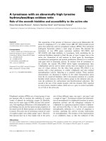
Fig 2.1 Schematic presentations of thio-capped CdTe quantum dots.
(a) 1
st
step: formation of CdTe precursors by introducing H
2
Te gas into the aqueous solution of Cd
precursors complexed by thiols. (b) 2
nd
step: heating and stirring to achieve quantum dots
growth and crystallization. [32]
The important part of this setup was the connecting tube for introducing the H
2
Te gas, which
should be as short as possible and the tube should be made of glass or another inert material. The use of
glass joints and connections is strongly recommended due to the high reactivity of H
2
Te gas with rubber
and common polymer tubes. The use of relatively small and well-deaerated flask for the generation of
H
2
Te may also help to reduce undesirable losses of this gas. Special precautions should be taken against
the possible leakage of the non-reacted H
2
Te. We note that the synthetic procedure described above is
easily up-scalable. Meanwhile, H
2
Te gas can be generated for the synthesis of CdTe quantum dots as well
as other tellurides, like HgTe [33, 34] or ZnTe [35] taking advantage of reaction (2.4).
2.3 Experimental Section
CdTe quantum dots could survive in many different environments, depending on what ligand
they attach to. In order to be better suited for biological applications, only aqueous soluble CdTe quantum
13
dots have been synthesized. But with different ligands we have the option to allow the quantum dots to be
stabilized in many different pH values. The most frequently used organic thiol capping ligands are
thioglycolic acid (TGA), mecaptoacetic acid (MPA), L-Cysteine or 2-mercaptoethylamine (or
cysteamine, namely CA). Both TGA and MPA allow the synthesis of the most stable (typically, for years)
aqueous solutions of CdTe quantum dots possessing negative charge due to the presence of surface
carboxylic groups. Cysteamine-stabilized quantum dots possess moderate photostability (although they
may be stable for years as well being kept in darkness) and attract an interest due to surface amino-
functionality and positive surface charge in neutral and slightly acidic media. Other thiol stabilizers are
mainly used when some specific functionalities are envisaged, the over view of them may be found in
[32].
2.3.1 Synthesis of water soluble CdTe quantum dots
Cadmium perchlorate hydrate (Cd(ClO
4
)
2
·6H
2
O), thioglycolic acid (TGA), sodium hydroxide
(NaOH), L-Cysteine, mercury perchlorate hydrate (Hg(ClO
4
)
2
·H
2
O) were purchased from Sigma-Aldrich,
St. Louis, MO, USA. Al
2
Te
3
lump material and 2-Mercaptoethylamine hydrochloride (CA) were
purchased from Alfa Aesar, Ward Hill, MA. H
2
SO
4
(95~98%) was purchased from Pharmo-APPER
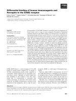
Company. All chemicals were used as received without any further purification process. Please refer the
chemical structure of the three kinds of stabilizers as in Fig 2.2.
Fig 2.2 Schematic representation of the CdTe quantum dots with three kinds of stabilizers
14
2.3.1.1 TGA stabilized CdTe quantum dots
The setup used was described in Section 2.2. Dissolve 4.70 mmol (1.973 g) of Cd(ClO
4
)
2
·6H
2
O
into 250 mL deionized water in a beaker. After the Cd precursor salt had been fully dissolved to result a
clear solution, 793.9 µL of thioglycolic acid (TGA) (11.4 mmol) with concentration of 98% was added,
and solution become turbid with white color. The pH value of the solution was carefully adjusted by
adding of NaOH solution dropwisely with concentration of 0.5 M until it reached 11.5. Then the solution
was transferred into a 500 mL three neck flask. The solution was bubbled with nitrogen or Ar inert gas
for approximately 30 min. The H
2
Te gas was introduced with the inert gas flow from flask A into flask B
by adding 3 mL of 0.5 M H
2
SO
4
into flask A which had 0.4 g Al
2
Te
3
power in it using a injector
puncturing through the plastic stopper. Then the solution became red-orange instantaneously in flask B.
Continue introducing the gas for 5 to 10 min until there was no more H
2
Te generated. Then tubes were
disassembled on flask A and flask B. While continue stirring, a condenser and two stoppers were attached
on flask B and heating was started in order to raise the temperature of the solution to 100 for different
period amount of time for the quantum dots to initiate the particle growth. The solution gave off green
luminescence after exposing by UV light bulb after heating for 30 min and red luminescence after heating
for 30 hours. After that, continuous heating decreased the luminescence intensity.
2.3.1.2 L-Cysteine stabilized CdTe quantum dots
The process is similar as the one described previously in Section 2.3.1.1 as using the TGA as the
stabilizer, but with only a modification of replacing TGA with L-Cysteine of 1.379 g (as 11.4 mmol).
Note: L-Cysteine is a special amino acid and need to be stored in the fridge with the temperature to be
around 4 . Storing in ambient temperature will result deterioration of this chemical and the solution will
become turbid even the pH value has been adjusted to 11.5.)
Compared with ones stabilized by TGA, L-Cysteine stabilized CdTe quantum dots grow much
faster. It takes approximately 7 hours for the quantum dots to reach the same red color as the ones
stabilized by TGA.
2.3.1.3 CA stabilized CdTe quantum dots
The recipe for synthesizing the CA stabilized CdTe quantum dots is similar to that of the TGA
stabilized ones. There are two modifications. One is to use 1.295 g (11.4 mmol) CA instead of TGA. The
other is to modify the pH value to be 6.00 for adjusting the Cd precursor before introducing H
2
Te gas.
15
The chemical affinity of CA on the CdTe quantum dots is not as good as TGA. Therefore, after the H
2
Te
gas introduction, small lumps of quantum dots agglomeration appeared. In that case, just right before the
heating process, the coarse quantum dots solution was centrifuged with 3000 rpm to get rid of the
agglomeration. The clear, transparent orange like supernatant solution was transferred back into flask B
for heating. As heating goes on, the color of the solution became darker into red, and the luminescence it
gave off tuned from green to red when exposed by UV light bulb.
2.3.2 Synthesis of water soluble CdHgTe quantum dots
By using the quantum dots synthesized previously, we could obtain CdHgTe infrared emission
quantum dots by the following method. First dissolve Hg(ClO
4
)
2
·H
2
O into deionized water to make 25
mM solution. Then add the Hg precursor solution into the CdTe quantum dots solution with three kinds
of stabilizers: TGA, L-Cysteine and CA respectively. Note: adding Hg will result luminescence intensity
drop so, it is better to add small amount first (e.g. 20 µL) and then stir the sample for 10 min and then add
another time. Monitor the emission peak for the whole process until the emission peak red shifts to the
final desirable wavelength.
2.4 Characterization Section
Photoluminescence spectra were obtained from Shimadzu RF-5301PC Spectrofluorophotometer
with 400W monochromatized xenon lamp. UV absorption spectra were measured by UV-2450
Spectrophotometer E120V, Shimadzu. UV Quartz cuvettes, with 1 mm path length, inside width 10 mm
and 4512.512.5 mm dimension, were used for both optical properties measurement. Transmission
electron microscope (TEM) images were taken by JEOL JEM02100 instrument, with an accelerating
voltage of 200 kV. Samples for TEM were prepared by depositing a drop of CdTe quantum dots solution
onto a carbon-coated copper grid. The excess liquid was wiped away with filter paper and the grid was
dried in air.
2.5 Data Analysis and Discussion
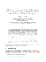
2.5.1 Transmission electron microscopy
Heating process will promote CdTe quantum dots particle growth, as well as crystallize the
particles, as it could be seen clearly in Fig 2.3. With different heating time, 65 min, 6.5 h, 14 h, 23 h
respectively, the quantum dots size grew from the approximately 2 nm core to approximately 6 nm in the
end for the 23 h sample.
16
Fig 2.3 TEM overview of the TGA stabilized CdTe quantum dots with different reaction time
(a) 65 min, (b) 6.5 h, (c) 14 h, (d) 23 h. Bar width 5 nm respectively.