A computer system consists of hardware, system programs, and application programs figs 8
Bạn đang xem bản rút gọn của tài liệu. Xem và tải ngay bản đầy đủ của tài liệu tại đây (445.94 KB, 44 trang )
8
MULTIPLE PROCESSOR SYSTEMS
8.1 MULTIPROCESSORS
8.2 MULTICOMPUTERS
8.3 DISTRIBUTED SYSTEMS
8.4 RESEARCH ON MULTIPLE PROCESSOR SYSTEMS
8.5 SUMMARY
C C C C
C C C C
M C
C
C C
C
Shared
memory
Inter-
connect
CPU
Local
memory
(a) (b) (c)
M C
C
M
C
M
C
M
C
C
M
C
C M
C M
C C
M M M M
C+ M C+ M C+ M
C+ M C+ M C+ M
Complete system
Internet
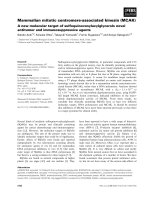
Fig. 8-1. (a) A shared-memory multiprocessor. (b) A message-
passing multicomputer. (c) A wide area distributed system.
CPU CPU M
Shared memory
Shared
memory
Bus
(a)
CPU CPU M
Private memory
(b)
CPU CPU M
(c)
Cache
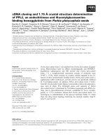
Fig. 8-2. Three bus-based multiprocessors. (a) Without caching.
(b) With caching. (c) With caching and private memories.
Memories
CPUs
Closed
crosspoint
switch
Open
crosspoint
switch
(a)
(b)
(c)
Crosspoint
switch is closed
Crosspoint
switch is open
000
001
010
011
100
101
110
111
100
101
110
111
000
001
010
011
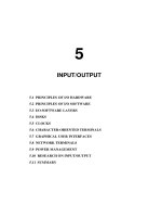
Fig. 8-3. (a) An 8 × 8 crossbar switch. (b) An open crosspoint.
(c) A closed crosspoint.
A
B
X
Y
(a) (b)
Module Address Opcode Value
Fig. 8-4. (a) A 2 × 2 switch. (b) A message format.
CPUs
b
b
b
b
a
aa
a
3 Stages
Memories
000
001
010
011
100
101
110
111
000
001
010
011
100
101
110
111
1A
1B
1C
1D
2A
2B
2C
2D
3A
3B
3C
3D
Fig. 8-5. An omega switching network.
Directory
Node 0 Node 1 Node 255
(a)
(b)
Bits
8186
(c)
Interconnection network
CPU Memory
Local bus
CPU Memory
Local bus
CPU Memory
Local bus
Node Block Offset
0
1
2
3
4
0
0
1
0
0
2
18
-1
82
…
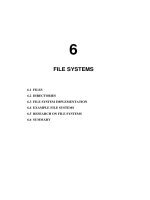
Fig. 8-6. (a) A 256-node directory-based multiprocessor. (b) Divi-
sion of a 32-bit memory address into fields. (c) The directory at
node 36.
Has
private
OS
CPU 1
Has
private
OS
CPU 2
Has
private
OS
CPU 3
Has
private
OS
CPU 4
Memory I/O
12
Data
Data
34
Data Data
OS code
Bus
Fig. 8-7. Partitioning multiprocessor memory among four CPUs,
but sharing a single copy of the operating system code. The boxes
marked Data are the operating system’s private data for each CPU.
Master
runs
OS
CPU 1
Slave
runs user
processes
CPU 2
Slave
runs user
processes
CPU 3
User
processes
OS
CPU 4 Memory
I/O
Bus
Slave
runs user
processes
Fig. 8-8. A master-slave multiprocessor model.
Runs
users and
shared OS
CPU 1
Runs
users and
shared OS
CPU 2
Runs
users and
shared OS
CPU 3
Runs
users and
shared OS
OS
CPU 4 Memory
I/O
Locks
Bus
Fig. 8-9. The SMP multiprocessor model.
CPU 1 Memory CPU 2
Bus
Word
1000 is
initially 0
1. CPU 1 reads a 0
3. CPU 1 writes a 1
2. CPU 2 reads a 0
4. CPU 2 writes a 1
Fig. 8-10. The TSL instruction can fail if the bus cannot be locked.
These four steps show a sequence of events where the failure is
demonstrated.
CPU 3
CPU 3 spins on this (private) lock
CPU 4 spins on this (private) lock
CPU 2 spins on this (private) lock
When CPU 1 is finished with the
real lock, it releases it and also
releases the private lock CPU 2
is spinning on
CPU 1
holds the
real lock
Shared memory
4
2
3
1
Fig. 8-11. Use of multiple locks to avoid cache thrashing.
0
4
8
12
1
5
9
13
2
6
10
14
3
7
11
15
A B C
D E
F
G H I
J K
L M N
7
5
4
2
1
0
Priority
CPU
0
A
8
12
1
5
9
13
2
6
10
14
3
7
11
15
B C
D E
F
G H I
J K
L M N
7
5
4
2
1
0
Priority
CPU 4
goes idle
CPU 12
goes idle
0
A
8
B
1
5
9
13
2
6
10
14
3
7
11
15
C
D E
F
G H I
J K
L M N
7
5
4
2
333
666
1
0
Priority
(a) (b) (c)
Fig. 8-12. Using a single data structure for scheduling a multipro-
cessor.
0 1 2 3 4 5 6 7
8 9 10 11 12 13 14 15
16 17 18 19 20 21 22 23
24 25 26 27 28 29 30 31
4-CPU partition
12-CPU partition
Unassigned CPU
6-CPU partition
8-CPU partition
Fig. 8-13. A set of 32 CPUs split into four partitions, with two
CPUs available.
A
0
B
0
A
0
B
0
A
0
B
0
B
1
A
1
B
1
A
1
B
1
A
1
Thread A
0
running
0 100 200 300 400 500 600
CPU 0
CPU 1
Time
Request 1
Request 2
Reply 2
Reply 1
Fig. 8-14. Communication between two threads belonging to
process A that are running out of phase.
0
1
2
3
4
5
6
7
012345
A
0
B
0
B
1
D
1
E
2
A
1
B
1
D
1
E
2
A
1
A
2
B
2
D
2
E
3
A
2
B
2
D
2
E
3
A
3
D
3
E
4
A
3
C
0
D
3
E
4
C
1
D
4
E
5
A
4
C
1
D
4
E
5
C
2
E
0
E
6
A
5
C
2
E
0
E
6
C
0
A
4
A
5
D
0
E
1
A
0
B
0
D
0
E
1
CPU
Time
slot
Fig. 8-15. Gang scheduling.
(a)
(d)
(b)
(e)
(c)
(f)
Fig. 8-16. Various interconnect topologies. (a) A single switch.
(b) A ring. (c) A grid. (d) A double torus. (e) A cube. (f) A 4D
hypercube.
CPU 1
Input port
(a)
Output port
Entire
packet
Entire
packet
Four-port
switch
C
A
CPU 2
Entire
packet
D
B
(b)
C
A
D
B
(c)
C
A
D
B
Fig. 8-17. Store-and-forward packet switching.
CPU
CPU
CPU
CPU
Switch
Node 2
Main RAM
Main RAM
Node 4
Interface
board
Optional
on- board
CPU
Interface
board
RAM
Node 3
Main RAM
Main RAM
Node 1
3
2
1
4
5
User
OS
Fig. 8-18. Position of the network interface boards in a multicom-
puter.
Node 1 Node 2
CPUCPU
Switch
7
2
3
4
5
6
11000000
10000000
Bit map
Interface board
RAM
Main RAMMain RAM
Receive
ring
CPU
Send ring
7
0
1
2
3
4
5
6
0
1
OS
OS
Fig. 8-19. Use of send and receive rings to coordinate the main
CPU with the on-board CPU.
Sender blocked
Sender
blocked
Trap to kernel,
sender blocked
Message being sent
Message being sent
Sender running
Sender running
Return
Sender running
Sender running
Trap
Message
copied to a
kernel buffer
Return from kernel,
sender released
(a)
(b)
Fig. 8-20. (a) A blocking send call. (b) A nonblocking send call.
Client CPU
Client
stub
Client
2
1
Operating system
Server CPU
Server
stub
4
3
5
Operating system
Server
Network
Fig. 8-21. Steps in making a remote procedure call. The stubs are
shaded gray.
(a)
Machine 1 Machine 2
Run-time
system
Operating
system
Shared memory
Application
Hardware
Run-time
system
Operating
system
Application
Hardware
(b)
Machine 1 Machine 2
Run-time
system
Operating
system
Shared memory
Application
Hardware
Run-time
system
Operating
system
Application
Hardware
(c)
Machine 1 Machine 2
Run-time
system
Operating
system
Shared memory
Application
Hardware
Run-time
system
Operating
system
Application
Hardware
Fig. 8-22. Various layers where shared memory can be imple-
mented. (a) The hardware. (b) The operating system. (c) User-
level software.
Globally shared virtual memory consisting of 16 pages
Memory
Network
(a)
(b)
(c)
0123456789101112131415
CPU 0
025
9
CPU 1
136
810
CPU 2
4711
12 14
CPU 3
13 15
CPU 0
025
9
CPU 1
136
8
10
10
CPU 2
4711
12 14
CPU 3
13 15
CPU 0
025
9
CPU 1
136
810
CPU 2
4711
12 14
CPU 3
13 15
Fig. 8-23. (a) Pages of the address space distributed among four
machines. (b) Situation after CPU 1 references page 10.
(c) Situation if page 10 is read only and replication is used.
CPU 1
Code using
variable A
A
B
Shared
page
CPU 2
Code using
variable B
A
B
Network
A and B are unrelated
shared variables that just
happen to be on the same page
Fig. 8-24. False sharing of a page containing two unrelated vari-
ables.