Tiêu chuẩn iso 02017 1 2005
Bạn đang xem bản rút gọn của tài liệu. Xem và tải ngay bản đầy đủ của tài liệu tại đây (263.16 KB, 24 trang )
INTERNATIONAL
STANDARD
ISO
2017-1
First edition
2005-02-01
Mechanical vibration and shock —
Resilient mounting systems —
Part 1:
Technical information to be exchanged
for the application of isolation systems
--`,,,```-`-`,,`,,`,`,,`---
Vibrations et chocs mécaniques — Systèmes de montage résilients —
Partie 1: Informations techniques à échanger pour l'application
des systèmes d'isolation
Reference number
ISO 2017-1:2005(E)
Copyright International Organization for Standardization
Reproduced by IHS under license with ISO
No reproduction or networking permitted without license from IHS
© ISO 2005
Not for Resale
ISO 2017-1:2005(E)
PDF disclaimer
This PDF file may contain embedded typefaces. In accordance with Adobe's licensing policy, this file may be printed or viewed but
shall not be edited unless the typefaces which are embedded are licensed to and installed on the computer performing the editing. In
downloading this file, parties accept therein the responsibility of not infringing Adobe's licensing policy. The ISO Central Secretariat
accepts no liability in this area.
Adobe is a trademark of Adobe Systems Incorporated.
--`,,,```-`-`,,`,,`,`,,`---
Details of the software products used to create this PDF file can be found in the General Info relative to the file; the PDF-creation
parameters were optimized for printing. Every care has been taken to ensure that the file is suitable for use by ISO member bodies. In
the unlikely event that a problem relating to it is found, please inform the Central Secretariat at the address given below.
© ISO 2005
All rights reserved. Unless otherwise specified, no part of this publication may be reproduced or utilized in any form or by any means,
electronic or mechanical, including photocopying and microfilm, without permission in writing from either ISO at the address below or
ISO's member body in the country of the requester.
ISO copyright office
Case postale 56 • CH-1211 Geneva 20
Tel. + 41 22 749 01 11
Fax + 41 22 749 09 47
Web www.iso.org
Published in Switzerland
ii
Copyright International Organization for Standardization
Reproduced by IHS under license with ISO
No reproduction or networking permitted without license from IHS
© ISO 2005 – All rights reserved
Not for Resale
ISO 2017-1:2005(E)
Contents
Page
--`,,,```-`-`,,`,,`,`,,`---
Foreword ............................................................................................................................................................ iv
Introduction ........................................................................................................................................................ v
1
Scope...................................................................................................................................................... 1
2
Normative references ........................................................................................................................... 1
3
Terms and definitions........................................................................................................................... 2
4
Purpose of vibration isolation (why isolate mechanical systems) .................................................. 2
5
5.1
5.2
What is to be isolated ........................................................................................................................... 3
Source isolation .................................................................................................................................... 3
Receiver isolation ................................................................................................................................. 3
6
Applicability of vibration isolation (when to isolate structures or mechanical systems) ............. 3
7
Measurement and evaluation of vibration conditions....................................................................... 4
8
Information for the choice of an isolation mounting system ........................................................... 4
9
9.1
9.2
9.3
Information to be supplied by the producer of the source or receiver ........................................... 4
General ................................................................................................................................................... 4
Information to be supplied by the source producer.......................................................................... 5
Information to be supplied by the receiver producer........................................................................ 6
10
10.1
10.2
Information to be supplied by the customer ...................................................................................... 7
Information to be supplied by the user of the source....................................................................... 7
Information to be supplied by the user of the receiver..................................................................... 8
11
11.1
11.2
11.3
11.4
11.5
Information to be provided by the supplier of the isolation system ............................................... 8
Physical data of the isolation system ................................................................................................. 8
Dynamic behaviour ............................................................................................................................... 9
Durability................................................................................................................................................ 9
Environmental data............................................................................................................................... 9
Maintenance data ................................................................................................................................ 10
12
Guidelines for the validation of isolation performance .................................................................. 10
Annex A (informative) Elements for vibration isolation ............................................................................... 11
Bibliography ..................................................................................................................................................... 17
iii
© ISO 2005 – All rights reserved
Copyright International Organization for Standardization
Reproduced by IHS under license with ISO
No reproduction or networking permitted without license from IHS
Not for Resale
ISO 2017-1:2005(E)
Foreword
ISO (the International Organization for Standardization) is a worldwide federation of national standards bodies
(ISO member bodies). The work of preparing International Standards is normally carried out through ISO
technical committees. Each member body interested in a subject for which a technical committee has been
established has the right to be represented on that committee. International organizations, governmental and
non-governmental, in liaison with ISO, also take part in the work. ISO collaborates closely with the
International Electrotechnical Commission (IEC) on all matters of electrotechnical standardization.
International Standards are drafted in accordance with the rules given in the ISO/IEC Directives, Part 2.
The main task of technical committees is to prepare International Standards. Draft International Standards
adopted by the technical committees are circulated to the member bodies for voting. Publication as an
International Standard requires approval by at least 75 % of the member bodies casting a vote.
Attention is drawn to the possibility that some of the elements of this document may be the subject of patent
rights. ISO shall not be held responsible for identifying any or all such patent rights.
ISO 2017-1 was prepared by Technical Committee ISO/TC 108, Mechanical vibration and shock.
This first edition of ISO 2017-1, together with ISO 2017-2, cancels and replaces ISO 2017:1982, which has
been technically revised.
ISO 2017 consists of the following parts, under the general title Mechanical vibration and shock — Resilient
mounting systems:
Part 1: Technical information to be exchanged for the application of isolation systems
Part 2: Technical information to be exchanged for the application of vibration isolation associated with
railway systems
--`,,,```-`-`,,`,,`,`,,`---
iv
Copyright International
Organization for Standardization
Reproduced by IHS under license with ISO
No reproduction or networking permitted without license from IHS
© ISO 2005 – All rights reserved
Not for Resale
ISO 2017-1:2005(E)
Introduction
This International Standard is limited to the consideration of resilient devices.
Some suppliers of shock and vibration isolators (resilient mounts) have experience covering a wide variety of
applications. In most instances, they are willing to use this background information for solving the user's
problems with isolators. However, it is frequently difficult for the supplier to provide this service, because the
customer, the user or the producer of the vibration source or receiver has not furnished sufficient information
regarding the application.
On the other hand, the user is sometimes handicapped in applying isolators properly because the supplier
does not furnish sufficient technical information. Consequently, the users must conduct their own experimental
evaluation of the isolator and may unknowingly duplicate work already carried out by the supplier.
With some vibration sources or receivers, the producer provides the isolating system. To do that, the producer
needs all the information from the customer relating to the future application, site and environment.
--`,,,```-`-`,,`,,`,`,,`---
This International Standard is intended to serve as guide for the exchange of technical information between
the customer, the supplier of resilient devices, and the producer of vibration sources or receivers, as required
for their proper application.
v
© ISO 2005 – All rights reserved
Copyright International Organization for Standardization
Reproduced by IHS under license with ISO
No reproduction or networking permitted without license from IHS
Not for Resale
--`,,,```-`-`,,`,,`,`,,`---
Copyright International Organization for Standardization
Reproduced by IHS under license with ISO
No reproduction or networking permitted without license from IHS
Not for Resale
INTERNATIONAL STANDARD
ISO 2017-1:2005(E)
Mechanical vibration and shock — Resilient mounting
systems —
Part 1:
Technical information to be exchanged for the application of
isolation systems
--`,,,```-`-`,,`,,`,`,,`---
1
Scope
This part of ISO 2017 establishes requirements to ensure the appropriate exchange of information between
users, manufacturers and suppliers of vibration sources and receivers regarding the application of isolation
systems. The sources and the receivers can be machines, structures, people or sensitive equipment
subjected to vibrations and shocks generated by machines, railways, road traffic and other external and
internal sources where the vibrations are usually transmitted through the ground to a building.
This part of ISO 2017 is applicable to the use of new products (source or receiver), and can also be applied to
previously installed products when the user wishes to solve a newly arisen vibration problem.
It is not to be considered as a manual for the design or installation of an isolation system. Examples of
elements of vibration isolation are shown in Annex A, for information only.
This part of ISO 2017 is intended to provide appropriate responses to questions highlighted by the producer
and users (e.g. why, what, when and how to isolate mechanical systems).
2
Normative references
The following normative documents are indispensable for the application of this document. For dated
references only the edition cited applies. For undated references, the latest edition of the referenced
document ( including any amendments) applies.
ISO 2041:1990, Vibration and shock — Vocabulary
ISO 9688:1990, Mechanical vibration and shock — Analytical methods of assessing shock resistance of
mechanical systems — Information exchange between suppliers and users of analyses
ISO 10846-4:2003, Acoustics and vibration — Laboratory measurement of vibro-acoustic transfer properties
of resilient elements — Part 4: Dynamic stiffness of elements other than resilient supports for translatory
motion
1
© ISO 2005 – All rights reserved
Copyright International Organization for Standardization
Reproduced by IHS under license with ISO
No reproduction or networking permitted without license from IHS
Not for Resale
ISO 2017-1:2005(E)
3
Terms and definitions
For the purposes of this document, the terms and definitions given in ISO 2041, ISO 9688 and ISO 10846-4
and the following apply.
3.1
resilient device
flexible element or system used between an equipment item and its supporting structure to attenuate the
transmission of shock or vibration from the equipment to the structure or from the structure to the equipment
3.2
vibration source
simple or multiple solid, liquid or gaseous body causing vibration in its environment
NOTE
This covers sources such as machinery, traffic, explosions, wave loading and wind loading.
3.3
vibration receiver
all structures or elements of structures responding to vibration energy emitted by an internal or external
source
--`,,,```-`-`,,`,,`,`,,`---
3.4
customer
user or purchaser of a product (building, machine, etc.)
3.5
producer
party constructing or manufacturing a product that needs to be isolated from internal or external vibration
3.6
isolation supplier
party responsible for providing and installing an isolation system which will meet the requirements to reduce
vibration as agreed upon with the customer
NOTE 1
In certain cases, the producer and the supplier may be the same party.
NOTE 2
The customer, the producer or the supplier may each mandate subcontractors to execute the work or to
purchase elements. From a legal point of view, all three remain responsible in the case of failure of the project.
4
Purpose of vibration isolation (why isolate mechanical systems)
The purpose of vibration isolation is to protect people and mechanical systems from vibrations and shocks by
taking action on the source or the receiver of the vibration. The purpose may include assurance of the
following:
a) the safety of the industrial building containing the vibrating equipment itself;
b) the safety and comfort of the operators of the vibrating machine;
c) the safety and comfort of bystanders near the vibrating machine;
d) the security of a building located close to a source of vibration, such as an industrial plant or railway;
e) the comfort of people in temporary or permanent habitations that may be subject to vibration excitation;
f)
the security of sensitive equipment in buildings;
g) the correct operation of the isolated equipment;
h) meeting regulatory requirements.
2
Copyright International Organization for Standardization
Reproduced by IHS under license with ISO
No reproduction or networking permitted without license from IHS
© ISO 2005 – All rights reserved
Not for Resale
ISO 2017-1:2005(E)
5
5.1
What is to be isolated
Source isolation
The purpose in this case is the protection of the environment in the vicinity of a vibrating source by modifying
the input at the source level. This may include
a)
isolation of the machine emitting vibrations,
b)
isolation of the rail track and surrounding subsystems, such as the soil systems for new and existing
railways, and
c)
isolation of the road embankment and viaducts for highways and removal (suppression) of irregularities.
5.2
Receiver isolation
--`,,,```-`-`,,`,,`,`,,`---
Where source isolation is impossible or impractical (i.e. environmental sources), as for railways or road traffic,
or where source isolation has proved unsatisfactory, receiver isolation is applied. Sometimes it is an
economical compromise. It may include applying isolation to
a)
a machine operator's workstation,
b)
a new building or elements of the building in the neighbourhood of a railway, tunnel, or heavy traffic
roadway,
c)
a sensitive building (concert halls, laboratories, or sensitive installations),
d)
the support of sensitive equipment (laser tables, computer discs, electronic microscopes, etc.), and
e)
isolation from environmental sources.
6 Applicability of vibration isolation (when to isolate structures or mechanical
systems)
A vibration isolation system may be used additionally to design measures for reducing vibration. It shall not be
substituted for such measures, but it may be applied as follows:
a)
when vibrating machines are designed or installed;
b)
when constructions, installations or buildings containing vibrating machines are designed or modified;
c)
when vibrating sources are displaced or modified;
d)
when structure-borne noises occur;
e)
when designing and constructing buildings, especially sensitive ones in the neighbourhood of railways or
high-traffic roads;
f)
when designing or ordering sensitive equipment;
g)
when receiving complaints from people working or living in the area of vibration sources;
h)
when the limiting values specified in legislation for vibration are exceeded.
3
© ISO 2005 – All rights reserved
Copyright International Organization for Standardization
Reproduced by IHS under license with ISO
No reproduction or networking permitted without license from IHS
Not for Resale
ISO 2017-1:2005(E)
7
Measurement and evaluation of vibration conditions
In order to choose the correct isolation mounting system, it is necessary to make prior measurement and
evaluation of vibration in the site.
Measurements shall be made under the environmental conditions relevant for the location of the source or
receiver. The measurements and analysis should help to provide an understanding of the origin of the
problem and possibly give an indication of the solutions. Measurements shall be made in accordance with an
appropriate standard and this standard shall be identified.
The measuring position shall be defined in a contract, and the mounting points of transducers and the
directions of measurements shall be reported.
These measurements shall include time history monitoring over a sufficiently long period to cover the working
cycle of the source of vibration.
For source measurements, analysis of frequency responses for the structures that transmit and receive
vibration will help to avoid coincidence between dominant frequencies of the source and the natural
frequencies of these structures.
For receiver measurements, determination of the background vibration shall be carried out in order to know
the inherent level below which no solution is normally necessary.
8
Information for the choice of an isolation mounting system
In order to select appropriate isolators and to correctly fit the isolation, an exchange of information is needed
between the producer, the supplier of the isolator and the customer. Clause 9 lists the information required for
optimized isolation. If the source or receiver producer is also the supplier of the isolation system, some of the
information requested may seem to be not relevant. Nevertheless, this information may be useful when
replacement parts have to be provided and should be part of the instruction handbook.
The choice of the isolation system shall take into consideration not only the static characteristics of the
isolated structure, but also its dynamic characteristics and the dynamic characteristics of its surrounding
structure (and other sources).
It will often be necessary for the supplier of a vibration isolation system to ask for more detailed information
from the user in order to provide the best possible solution.
The information is different in the case of source or receiver isolation.
In every case, the people concerned are
--`,,,```-`-`,,`,,`,`,,`---
the producer (of the source or receiver),
the supplier of the isolation, and
the customer of the source or receiver.
9
Information to be supplied by the producer of the source or receiver
9.1
General
The manufacturer shall supply to the user as much of the information listed in 9.2 and 9.3 as is needed to
ensure proper installation. If necessary, the manufacturer should obtain information from the supplier of the
vibration isolation system.
4
Copyright International Organization for Standardization
Reproduced by IHS under license with ISO
No reproduction or networking permitted without license from IHS
© ISO 2005 – All rights reserved
Not for Resale
ISO 2017-1:2005(E)
The main vibration sources to be considered in this part of ISO 2017 are machines.
9.2
Information to be supplied by the source producer
9.2.1
Machine drawing
A drawing shall be furnished giving the following:
the outline and installation of the machine, if appropriate, including an intermediate foundation specified
by the machine manufacturer;
b)
the overall dimensions;
c)
the total mass and the location of the centre of gravity (rotational inertia shall also be included);
d)
specifications of bolt sizes and special connectors for securing the machine; the locations of attachments,
tapped holes, tolerances, and any special material considerations shall be indicated on the drawing;
e)
identification and direction of the three mutually orthogonal axes of origin in the centre of gravity of the
unit to be isolated under conditions of preferred orientation;
f)
the normal machine orientation with respect to the vertical axis; the direction of the major shock or
vibration shall be indicated;
g)
feasible structural attachment points (these points frequently determine the isolation system in relation to
orientation, centre of gravity, etc.);
h)
the structure and dimensions of the supporting surface of the mechanism, with indication of the
connection of this surface to the mechanism body.
--`,,,```-`-`,,`,,`,`,,`---
a)
9.2.2
Vibration excitation
The vibration excitation by a machine as characterized by its exciting forces and couples as a function of
frequency, or in the form of a time history, shall be described in the detail necessary to ensure the safe
installation and use of the machinery.
Examples include the following:
a)
rotational frequency forces and couples;
b)
forces and couples caused by reciprocating masses;
c)
torque reaction couples;
d)
amplitudes and/or frequencies of fluid pulsation phenomena;
e)
frequencies of aerodynamic phenomena (e.g. for fans);
f)
electromagnetic forces and frequencies associated with electrical rotating machines or transformers;
g)
dynamic characteristics of the isolation system on which the mechanism has been tested;
h)
distribution of vibration (in three directions) over the surface of the mechanism mounting and where
electric cables and pipes may be mounted;
i)
factors ensuring that the isolation system does not introduce specific vibration levels that are detrimental
to the machine.
5
© ISO 2005 – All rights reserved
Copyright International Organization for Standardization
Reproduced by IHS under license with ISO
No reproduction or networking permitted without license from IHS
Not for Resale
ISO 2017-1:2005(E)
9.2.3
Special requirements
Special features peculiar to the equipment shall be covered in the machine description and by drawings.
Examples of such special features are as follows:
a)
electrical connectors, tubing, ducting or piping which might modify the mechanical response of the
mounting system (type, size, stiffness, etc.);
b)
externally applied forces and moments;
c)
required access areas;
d)
minimum clearance required for cooling air flow; any temperature gradients which might adversely affect
isolator operation shall be shown on the drawing and the expected temperature range shall be given;
e)
maximum clearance between the equipment and the foundation, where applicable;
f)
alignment requirements for shafts.
9.2.4
Electrical features
Provisions for grounding and applicable specifications shall be indicated in a note on the drawing.
9.2.5
Special requirements for mechanical stability
Special requirements for mechanical stability shall be given. For example, special care is needed where
equipment with a high or variable centre of gravity is supported by isolators located below the centre of
gravity, or where uncompensated side thrusts exist.
9.3
Information to be supplied by the receiver producer
9.3.1
Building
The designer and constructor of the building shall supply the following information to the supplier of the
isolation system:
a)
a drawing of the structure detailing the nature, dimensions and the position of the bearing elements (steel,
concrete, combined);
b)
category of the foundation expected to be used (shallow, deep);
c)
position of the foundation in relation to tunnels or traffic roads;
d)
position of any underground water table;
e)
function of the future building (offices, laboratories, habitation, manufacturing of particular equipment);
f)
maximum admissible vibration level for equipment to be used in the building.
9.3.2
Sensitive equipment
The producer of sensitive equipment shall supply the following information about the equipment to help the
user to choose the proper location and set up of the equipment:
a)
overall dimensions;
b)
total mass and the position of the centre of gravity;
--`,,,```-`-`,,`,,`,`,,`---
6
Copyright International Organization for Standardization
Reproduced by IHS under license with ISO
No reproduction or networking permitted without license from IHS
© ISO 2005 – All rights reserved
Not for Resale
ISO 2017-1:2005(E)
c)
feasible structure attachment points (three points frequently determine the isolation system);
d)
acceptable vibration level measured at the base of the equipment;
e)
any particular natural frequency to be avoided at the equipment base.
Vehicles
--`,,,```-`-`,,`,,`,`,,`---
9.3.3
The designer of a vehicle shall supply the following information to the manufacturer of seats or secondary
elements (partitions, doors, etc.) and furniture in the case of boats:
a)
motor and transmission characteristics as well as intermediate systems, such as torque converters and
clutch systems;
b)
dominant frequency and frequency range of the rotating systems;
c)
natural frequency of the suspension systems;
d)
expected road and sea state characteristics for each vehicle category (e.g. private, agriculture, road and
construction engines, boat);
e)
maximum permissible level of vibration for the user of the vehicle;
f)
maximum permissible structure-borne sound (re-radiated) to be perceived by the user for each zone of
the vehicle.
10 Information to be supplied by the customer
10.1 Information to be supplied by the user of the source
10.1.1 Technical information on the surrounding structure of the machine
A brief description, sufficient for understanding the technical details of the proposed arrangement, shall be
provided. The following information should be included:
a)
type of structure in which the machine is to be mounted (e.g. ship, steel building, concrete building, power
plant) and its dynamic characteristics (e.g. resonance frequency, modes, damping);
b)
location in the structure (e.g. engine room, main deck, roof);
c)
data on the supporting structure (ground conditions, such as the permissible load of the ground, ground
water level versus floor, natural frequencies, and input mechanical impedance of the supporting
structure);
d)
isolation criteria or user’s criteria for acceptance (neighbourhood, such as residential area, industrial area;
type of neighbouring machines, such as testing machines, punching machines);
e)
possible seismic activity level.
10.1.2 Vibration and shock evaluation of the surrounding structure
The vibration and shock evaluation of the surrounding structure before the installation of the machine shall be
described with respect to the three axes in terms of the magnitude (displacement, velocity, or acceleration),
corresponding frequencies, and the duration over which this will occur. Time history, spectral analysis and
other descriptive parameters shall be included.
7
© ISO 2005 – All rights reserved
Copyright International Organization for Standardization
Reproduced by IHS under license with ISO
No reproduction or networking permitted without license from IHS
Not for Resale
ISO 2017-1:2005(E)
10.1.3 Environment
The user shall supply, as applicable, the following information on the climatic environment:
a)
upper and lower temperature limits;
b)
humidity, presence of water, sand or dust, salt spray, ozone, oils, solvents, radiation, etc.
10.2 Information to be supplied by the user of the receiver
Existing buildings are the main receivers of vibration, but it is often economically impractical to isolate the
building except for certain important projects where the cost is deemed acceptable. In this case, only the
substructure isolation (“box in the box”) technique may be applied.
The receiver isolation mainly concerns sensitive equipment or machine operator work stations. The isolation
system may be designated by the producer or by the supplier of isolation according to user’s demand.
A brief description, sufficient for a complete understanding of the technical details of the proposed system,
shall be provided. The following information should be included:
a)
type of equipment to be isolated;
b)
type of structure in which the equipment is mounted;
c)
location of the equipment in the structure;
d)
data on the supporting structure (e.g. natural frequencies, dynamic stiffness, coupling with the vibration
isolation system);
e)
criteria for acceptance of isolation efficiency;
f)
description of vibration conditions in the surrounding structure, with respect to the three orthogonal axes,
by amplitude, frequencies and duration;
g)
information on environmental condition (e.g. temperature, humidity).
11 Information to be provided by the supplier of the isolation system
11.1 Physical data of the isolation system
The supplier of the isolation system shall provide the following detailed information on the characteristics of
the isolation system:
a)
type of isolation system;
b)
materials of the isolation system;
c)
mass of the isolation system;
d)
levelling features;
e)
static stiffness of isolators;
f)
maximum and minimum weight forces (expressed in newtons) under the operation conditions of the
machine;
--`,,,```-`-`,,`,,`,`,,`---
8
Copyright International Organization for Standardization
Reproduced by IHS under license with ISO
No reproduction or networking permitted without license from IHS
© ISO 2005 – All rights reserved
Not for Resale
ISO 2017-1:2005(E)
g)
dimensions, structure, mass, location and orientation of the isolation system (e.g. drawing), including any
intermediate structure;
h)
any creep of the isolators relative to load and time;
i)
special requirements for air-mounted systems;
j)
chemical-, sunlight- and oil-resistant isolator materials;
k)
maximum stress and strain relationships (nonlinear characteristics).
11.2 Dynamic behaviour
The supplier shall describe the translational and rotational dynamic behaviour of the isolation system in terms
of dynamic stiffness. The environmental conditions and the rate of loading under which the load-deflection
data were obtained shall be described and tolerances shall be given. However, where necessary, as an
alternative the supplier may describe the dynamic behaviour by transmissibility characteristics measured in a
test set-up that is fully described. Dynamic behaviour may be related to variations in the following input
parameters:
a)
frequency response as a function of load;
b)
amplitude;
c)
temperature;
d)
damping: dynamic stiffness and damping for direction (for details of orientation and frequency range of
interest, see ISO 10846-1, ISO 10846-2 and ISO 10846-3).
The supplier shall describe the performance of the isolation in the three principal directions, indicating
applicable frequencies and internal resonance.
11.3 Durability
The supplier shall present information on the durability and anticipated changes in physical characteristics
during the life of the material, such as the following:
a)
endurance limit associated with repeated deflections and shocks;
b)
creep (permanent deformation) data, where applicable, and how the data were obtained;
c)
ageing effects due to storage in specified environments, including maximum and minimum temperatures;
d)
maximum permissible displacement before restraint is required.
11.4 Environmental data
The supplier shall supply the following information on the isolators, as necessary to ensure proper use:
a)
upper and lower temperature limits beyond or below which the isolator under rated loads will not properly
perform its function or will undergo permanent changes in characteristics;
b)
ability of the isolator to withstand corrosion or deterioration caused by such factors as humidity, water,
salt spray, fungus, ozone, oils and fuels, corrosive vapours or sunshine;
c)
ability to perform under adverse conditions, for example, in an atmosphere loaded with sand or dust;
d)
permissible storage environment.
© ISO 2005 – All rights reserved
Copyright International Organization for Standardization
Reproduced by IHS under license with ISO
No reproduction or networking permitted without license from IHS
--`,,,```-`-`,,`,,`,`,,`---
Not for Resale
9
ISO 2017-1:2005(E)
11.5 Maintenance data
The supplier shall supply details of any maintenance, periodical inspection and service requirements.
12 Guidelines for the validation of isolation performance
Normally, the supplier of isolated machines or the supplier of isolating systems has contractual or guarantee
requirements to prove the performance of the vibration isolation after it is installed in the surrounding structure
of the source or of the receiver itself. This performance shall be evaluated by an experimental method.
Where machines are made by mass production, such evaluation may be performed under nominal installation
conditions, and that information may be used in qualifying the installed vibration performance. In such cases
the manufacturer shall provide information on the installation conditions that have been used for the
evaluation.
If relevant, the following requirements apply:
a)
measurement and evaluation of vibration shall be made by an independent party specialist before
installation; it shall be performed in predetermined measurement locations and under the environmental
operating conditions expected for the future machine;
b)
after installation, measurements shall be made at the same locations and conditions, using the
measurement method specified and the specified processing and analysis of the results;
c)
measurement positions and the measurement results shall be reported;
d)
acceptable values shall be communicated to the machine supplier (or machine/isolator supplier);
e)
limit values accepted by the supplier shall be specified in the contract;
f)
values measured shall be compared with the contractual limit values.
In the case of correction of an existing situation, the measurements should be made under the same
conditions as given in Clause 7 in defined positions. These positions should be the positions of the disturbed
subjects (operator’s or worker’s positions, office floors, neighbouring building, etc.).
As in Clause 7, acceptable limit values should be defined contractually between the user and the supplier.
After correction, measurements should be carried out as described in Clause 7. The results should be
compared to the contractual values.
In more complex situations, more detailed measurements will be required.
--`,,,```-`-`,,`,,`,`,,`---
10
Copyright International Organization for Standardization
Reproduced by IHS under license with ISO
No reproduction or networking permitted without license from IHS
© ISO 2005 – All rights reserved
Not for Resale
ISO 2017-1:2005(E)
Annex A
(informative)
Elements for vibration isolation
A.1 Object of this annex
This informative annex has the objective of helping the user to understand the different functions of isolation
systems. It does not represent an exhaustive survey of isolation systems and should not be used as guidance
for choice of an isolation system.
A.2 Springs
A.2.1 General
Springs are used to provide elastic vibration and shock isolating supports for machines; i.e. they are
construction elements which deform, predominantly, elastically. Ideal springs cannot be realised in practice
since each spring shows a certain amount of mass and damping. While for the calculation of vibration in the
frequency range of interest in this part of ISO 2017, the mass of the spring may be ignored, the damping is
strongly dependent on the spring material.
A.2.2 Elastomer springs
Because of its elastic deformability and its small Young’s modulus, elastomers are appropriate materials for
springs. Compared to metal springs, elastomer springs have larger material damping.
Deformation characteristics, such as stiffness and damping, depend on the choice of basic material and the
components of the material mixture, as well as the shape of the spring. They are also affected by
environmental conditions such as temperature. The long-term creeping depends strongly on the composition
of the material. The material has viscoelastic properties.
Usually, the static and dynamic stiffnesses of elastomer springs are different; the dynamic stiffness is greater
than the static. The natural frequencies of the isolated system should be calculated only from the dynamic
stiffness. With elastomer springs, vertical natural frequencies can be between 6 Hz and 20 Hz.
In general, the load-deflection curve is nonlinear but, in practice, for operational loading it can be linearized.
The following factors are important for the load capacity and the durability of elastomer springs:
a)
materials, additions and hardness;
b)
design of the spring;
c)
static load and dynamic load;
d)
vibration amplitude and frequency of the vibrating system.
Because of their flexible design, connection with metal parts, and the wide range of possible material
combinations, these springs may be adapted to a wide range of applications.
Elastomer springs may be used as single elements or as distributed plates or mats.
--`,,,```-`-`,,`,,`,`,,`---
11
© ISO 2005 – All rights reserved
Copyright International Organization for Standardization
Reproduced by IHS under license with ISO
No reproduction or networking permitted without license from IHS
Not for Resale
ISO 2017-1:2005(E)
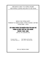
The detailed design of elastomer springs is determined by the type of loading (compression forces, shear
forces, torsion moments, bending moments, or combinations thereof). Figure A.1 shows some examples of
elastomer springs.
For large, distributed compression loads, elastomer springs in the form of plates or mats are common. The
vertical natural frequencies are usually higher than 12 Hz for these installations.
Figure A.1 — Examples of elastomer springs
Metal springs are not sensitive to large temperature differences and they are resistant to most organic
substances.
For the vibration isolation of machines, it is preferable to use metal springs that are made especially for this
purpose from spring steel in the form of wire strings, plates and rods. There is no significant difference
between the static and dynamic stiffnesses of metal springs. Depending on the type and design of the spring,
the load-deflection curve can be linear, progressive or digressive. With metal springs, vertical natural
frequencies of 1,5 Hz to 8 Hz can be achieved. Metal springs have the ability to store high deformation
energies at large deflection amplitudes. Their spring characteristics do not change with age.
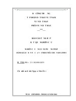
Figure A.2 shows examples of different types of metal springs and their load-deflection curves.
12
Copyright International Organization for Standardization
Reproduced by IHS under license with ISO
No reproduction or networking permitted without license from IHS
© ISO 2005 – All rights reserved
Not for Resale
--`,,,```-`-`,,`,,`,`,,`---
A.2.3 Metal springs
ISO 2017-1:2005(E)
a)
e)
Helical spring
Disc spring column of
single discs
b) Spiral spring
f)
c)
Disc spring column of
spring packets
(laminated single
discs)
Flexural spring
g) Laminated leaf spring
d) Conical spring
h) Ring spring
Key
F
is the load
s
is the deflection in the direction of load
h and t are dimensions
NOTE
The hatched areas indicate hysteresis due to friction damping.
Figure A.2 — Metal springs and their load-deflection curves (characteristic)
The helical compression spring is the metal spring generally used for the vibration isolation of machines.
Because of its largely linear characteristics over a wide deflection range (load-deflection curve) and the wide
choice of spring stiffness available, for all axes, this type of spring is particularly well suited for application to
the resilient mounting of machines of most types.
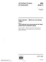
The transverse or horizontal spring constant of a helical compression spring can be varied over a wide range,
relative to the vertical spring constant, by an appropriate choice of spring dimensions. Figure A.3 shows an
example of a spring unit made of helical compression springs.
--`,,,```-`-`,,`,,`,`,,`---
13
© ISO 2005 – All rights reserved
Copyright International Organization for Standardization
Reproduced by IHS under license with ISO
No reproduction or networking permitted without license from IHS
Not for Resale
ISO 2017-1:2005(E)
Figure A.3 — Typical spring unit made of helical compression springs
A.2.4 Air springs
In principle, an air spring consists of a closed gas-filled volume with elastic sides (see Figure A.4). When the
load changes the spring deflects, by deflection of the elastic sides, causing a change of volume which results
in a change of pressure. This applies to pistons in cylinders as well as to the various bellows designs that are
manufactured. The deflection characteristics of air springs depend on the balance between the external load
and the pressure difference between the internal pressure and external pressure (e.g. atmosphere) multiplied
by the effective area depending on the internal gas used. The static and dynamic stiffnesses can be different.
--`,,,```-`-`,,`,,`,`,,`---
For level control, air springs are supplied in non-controllable and controllable designs.
Figure A.4 — Examples of air springs
A.3 Dampers
Dampers are used to limit the movement of elastically supported systems while passing through resonance in
the case of periodical excitation or in cases of shock or random excitation. They are mounted in parallel with
the spring units and convert mechanical energy to heat.
They are divided into dampers which utilize damping between rigid bodies (friction dampers, see Figure A.5)
and dampers which utilize energy exchange in liquid (liquid dampers, see Figure A.5) or gaseous media. The
14
Copyright International Organization for Standardization
Reproduced by IHS under license with ISO
No reproduction or networking permitted without license from IHS
© ISO 2005 – All rights reserved
Not for Resale