Tiêu chuẩn iso 01924 2 2008
Bạn đang xem bản rút gọn của tài liệu. Xem và tải ngay bản đầy đủ của tài liệu tại đây (223.41 KB, 20 trang )
INTERNATIONAL
STANDARD
ISO
1924-2
Third edition
2008-12-15
Paper and board — Determination of
tensile properties —
Part 2:
Constant rate of elongation method
(20 mm/min)
Papier et carton — Détermination des propriétés de traction —
Partie 2: Méthode à gradient d'allongement constant (20 mm/min)
--`,,```,,,,````-`-`,,`,,`,`,,`---
Reference number
ISO 1924-2:2008(E)
Copyright International Organization for Standardization
Provided by IHS under license with ISO
No reproduction or networking permitted without license from IHS
© ISO 2008
Not for Resale
ISO 1924-2:2008(E)
PDF disclaimer
This PDF file may contain embedded typefaces. In accordance with Adobe's licensing policy, this file may be printed or viewed but
shall not be edited unless the typefaces which are embedded are licensed to and installed on the computer performing the editing. In
downloading this file, parties accept therein the responsibility of not infringing Adobe's licensing policy. The ISO Central Secretariat
accepts no liability in this area.
Adobe is a trademark of Adobe Systems Incorporated.
Details of the software products used to create this PDF file can be found in the General Info relative to the file; the PDF-creation
parameters were optimized for printing. Every care has been taken to ensure that the file is suitable for use by ISO member bodies. In
the unlikely event that a problem relating to it is found, please inform the Central Secretariat at the address given below.
COPYRIGHT PROTECTED DOCUMENT
--`,,```,,,,````-`-`,,`,,`,`,,`---
© ISO 2008
All rights reserved. Unless otherwise specified, no part of this publication may be reproduced or utilized in any form or by any means,
electronic or mechanical, including photocopying and microfilm, without permission in writing from either ISO at the address below or
ISO's member body in the country of the requester.
ISO copyright office
Case postale 56 • CH-1211 Geneva 20
Tel. + 41 22 749 01 11
Fax + 41 22 749 09 47
Web www.iso.org
Published in Switzerland
ii
Copyright International Organization for Standardization
Provided by IHS under license with ISO
No reproduction or networking permitted without license from IHS
© ISO 2008 – All rights reserved
Not for Resale
ISO 1924-2:2008(E)
Contents
Page
Foreword ............................................................................................................................................................iv
Introduction.........................................................................................................................................................v
1
Scope ......................................................................................................................................................1
2
Normative references............................................................................................................................1
3
Terms and definitions ...........................................................................................................................2
4
Principle..................................................................................................................................................2
5
Apparatus ...............................................................................................................................................3
6
Calibration and adjustment of apparatus ...........................................................................................4
7
7.1
7.2
7.3
Sampling and preparation of test pieces ............................................................................................4
Sampling.................................................................................................................................................4
Conditioning ..........................................................................................................................................4
Preparation of test pieces.....................................................................................................................5
8
Procedure ...............................................................................................................................................5
9
9.1
9.2
9.3
9.4
9.5
9.6
9.7
Calculation and report ..........................................................................................................................6
General ...................................................................................................................................................6
Tensile strength .....................................................................................................................................6
Tensile index ..........................................................................................................................................6
Strain at break........................................................................................................................................6
Tensile energy absorption....................................................................................................................7
Tensile energy absorption index .........................................................................................................7
Modulus of elasticity .............................................................................................................................7
10
10.1
10.2
10.3
Precision.................................................................................................................................................8
General ...................................................................................................................................................8
Repeatability ..........................................................................................................................................8
Reproducibility ......................................................................................................................................8
11
Test report ............................................................................................................................................10
Annex A (normative) Calibration of the tensile testing machine .................................................................11
Bibliography......................................................................................................................................................12
--`,,```,,,,````-`-`,,`,,`,`,,`---
iii
© ISO 2008 – All rights reserved
Copyright International Organization for Standardization
Provided by IHS under license with ISO
No reproduction or networking permitted without license from IHS
Not for Resale
ISO 1924-2:2008(E)
Foreword
ISO (the International Organization for Standardization) is a worldwide federation of national standards bodies
(ISO member bodies). The work of preparing International Standards is normally carried out through ISO
technical committees. Each member body interested in a subject for which a technical committee has been
established has the right to be represented on that committee. International organizations, governmental and
non-governmental, in liaison with ISO, also take part in the work. ISO collaborates closely with the
International Electrotechnical Commission (IEC) on all matters of electrotechnical standardization.
International Standards are drafted in accordance with the rules given in the ISO/IEC Directives, Part 2.
The main task of technical committees is to prepare International Standards. Draft International Standards
adopted by the technical committees are circulated to the member bodies for voting. Publication as an
International Standard requires approval by at least 75 % of the member bodies casting a vote.
Attention is drawn to the possibility that some of the elements of this document may be the subject of patent
rights. ISO shall not be held responsible for identifying any or all such patent rights.
ISO 1924-2 was prepared by Technical Committee ISO/TC 6, Paper, board and pulps, Subcommittee SC 2,
Test methods and quality specifications for paper and board.
This third edition cancels and replaces the second edition (ISO 1924-2:1994), which has been technically
revised with respect to terms and definitions (in order to be in line with the terms and definitions used in
ISO 1924-3[1]). The numbering of clauses and their contents have been changed to be congruent with
ISO 1924-3.
ISO 1924 consists of the following parts, under the general title Paper and board — Determination of tensile
properties1):
⎯
Part 2: Constant rate of elongation method (20 mm/min)
⎯
Part 3: Constant rate of elongation method (100 mm/min)
--`,,```,,,,````-`-`,,`,,`,`,,`---
1)
ISO 1924-1, Constant rate of loading method, was withdrawn in 2004 as it was considered obsolete.
iv
Copyright International Organization for Standardization
Provided by IHS under license with ISO
No reproduction or networking permitted without license from IHS
© ISO 2008 – All rights reserved
Not for Resale
ISO 1924-2:2008(E)
Introduction
The method for determination of tensile properties specified in this part of ISO 1924 is the one most commonly
used. It is related to the method specified in ISO 1924-3. In this part of ISO 1924 (ISO 1924-2), the constant
rate of elongation applied is 20 mm/min, whereas in ISO 1924-3, the constant rate of elongation applied is
100 mm/min.
Since the results of a tensile test depend on the rate of elongation applied, this part of ISO 1924 and
ISO 1924-3 will not give the same results. The rate dependence can vary according to paper grade and is
different for tensile strength, strain at break, tensile energy absorption and modulus of elasticity.
NOTE 1
In most cases, the tensile properties can increase by 5 % to 15 % when the rate of elongation is increased
from 20 mm/min (180 mm test span length) to 100 mm/min (100 mm test span length).
NOTE 2
In this part of ISO 1924, the same terminology and symbols are used as in ISO 1924-3 and in general
literature concerning materials physics and mechanics.
--`,,```,,,,````-`-`,,`,,`,`,,`---
v
© ISO 2008 – All rights reserved
Copyright International Organization for Standardization
Provided by IHS under license with ISO
No reproduction or networking permitted without license from IHS
Not for Resale
--`,,```,,,,````-`-`,,`,,`,`,,`---
Copyright International Organization for Standardization
Provided by IHS under license with ISO
No reproduction or networking permitted without license from IHS
Not for Resale
INTERNATIONAL STANDARD
ISO 1924-2:2008(E)
Paper and board — Determination of tensile properties —
Part 2:
Constant rate of elongation method (20 mm/min)
Scope
This part of ISO 1924 specifies a method for measuring the tensile strength, strain at break and tensile energy
absorption of paper and board, using a testing machine operating at a constant rate of elongation
(20 mm/min). This part of ISO 1924 also specifies equations for calculating the tensile index, the tensile
energy absorption index and the modulus of elasticity.
Testing in conformance with this part of ISO 1924 always includes the measurement of tensile strength.
Measurement or calculation of other properties is subject to agreement between the parties concerned.
This part of ISO 1924 is applicable to all papers and boards, including papers with a high strain at break if the
results are within the capacity of the testing machine. It also applies to the components of corrugated board
but not, however, to corrugated board itself.
This part of ISO 1924 is not applicable to tissue paper and tissue products for which ISO 12625-4[2] is
applicable. For the determination of tensile properties of laboratory sheets, ISO 5270[3] is recommended.
2
Normative references
The following referenced documents are indispensable for the application of this document. For dated
references, only the edition cited applies. For undated references, the latest edition of the referenced
document (including any amendments) applies.
ISO 186, Paper and board — Sampling to determine average quality
ISO 187, Paper, board and pulps — Standard atmosphere for conditioning and testing and procedure for
monitoring the atmosphere and conditioning of samples
ISO 534, Paper and board — Determination of thickness, density and specific volume
ISO 536, Paper and board — Determination of grammage
1
© ISO 2008 – All rights reserved
Copyright International Organization for Standardization
Provided by IHS under license with ISO
No reproduction or networking permitted without license from IHS
Not for Resale
--`,,```,,,,````-`-`,,`,,`,`,,`---
1
ISO 1924-2:2008(E)
3
Terms and definitions
For the purposes of this document, the following terms and definitions apply.
3.1
tensile strength
maximum tensile force per unit width that paper and board will withstand before breaking under the conditions
defined in this International Standard
3.2
tensile index
tensile strength divided by the grammage
3.3
elongation
increase in length of a test piece
NOTE
Elongation is expressed in millimetres.
3.4
strain
ratio of the elongation of a test piece to the initial test length
NOTE 1
Strain is expressed as a percentage of the initial test length.
NOTE 2
The initial test length of the test piece is the same as the initial span between the clamping lines.
3.5
strain at break
ratio of the measured elongation at the moment of rupture of a test piece of paper, when extended under the
conditions defined in the standard method of test, to the initial test length
--`,,```,,,,````-`-`,,`,,`,`,,`---
3.6
tensile energy absorption
amount of energy per unit surface area of a test piece when it is strained to the maximum tensile force
NOTE
Surface area is calculated as test length multiplied by width.
3.7
tensile energy absorption index
tensile energy absorption divided by the grammage
3.8
modulus of elasticity
maximum slope of the force-elongation curve multiplied by the initial length divided by the width and the
thickness of the test piece
NOTE
4
See also Figure 2.
Principle
A test piece of given dimensions is strained to break at a constant rate of elongation using a testing machine
that records both the tensile force and, if required, the elongation. If the tensile force and elongation are
continuously recorded, the strain at break, the tensile energy absorption and the modulus of elasticity may be
determined.
From the recorded data, and the knowledge of the grammage of the sample, the tensile index and the tensile
energy absorption index may be calculated.
2
Copyright International Organization for Standardization
Provided by IHS under license with ISO
No reproduction or networking permitted without license from IHS
© ISO 2008 – All rights reserved
Not for Resale
ISO 1924-2:2008(E)
5
Apparatus
5.1 Tensile testing machine, designed to extend a test piece of given dimensions at an appropriate
constant rate of elongation (20 mm/min), and to measure the tensile force and, if required, the elongation
produced.
The tensile testing machine includes means of measuring and indicating the tensile force to an accuracy of
± 1 % of the true force and, if required, the elongation to an accuracy of ± 0,1 % elongation. The tensile force
may be recorded as a function of the elongation on an electronic integrator or an equivalent device.
NOTE 1
The accuracy of measurement of elongation is very important. An appropriate extensometer, placed directly
on the test piece, is recommended for accurate measurement of true elongation (see ISO 9513, class 1 or class 0,5). This
is to avoid the possibility of including in the measurement any apparent elongation which can result from undetected
slippage of the test piece in the clamps or from the take-up in the joints of the apparatus. The latter is dependent upon the
load applied and the error can increase due to wear of the joints of an apparatus which has been in use for some time. It is
advisable that means be applied to limit additional loads, which an extensometer would apply to the test piece, to the
required accuracy of the tensile force.
The tensile testing machine also includes two clamps, for holding a test piece of the required width (see 7.3).
Each clamp shall be designed to grip the test piece firmly, but without damage or slippage, along a straight
line across the full width of the test piece and have a means of adjusting the clamping force. The clamping
surfaces of the clamps shall be in the same plane and so aligned that they hold the test piece in that plane
throughout the test.
NOTE 2
It is advisable that the clamps grip the test piece between a cylindrical and a flat surface, or between two
cylindrical surfaces, with the plane of the test piece tangential to the cylindrical surface. Other types of clamps can be used
provided no slippage of, or damage to, the test piece occurs during test.
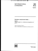
When the test piece is clamped, the clamping lines shall be parallel to each other within a maximum angle
of 1° (see Figure 1). In addition, the clamping lines shall remain perpendicular to the direction of the applied
tensile force, and to the long dimension of the test piece, to within a maximum of 1°, while under load
(see Figure 1). The distances between the clamping lines shall be adjustable to the test length required to
within ±1 mm.
a
b
Clamping lines parallel to each other within a maximum angle of 1°.
Centreline of test piece perpendicular to clamping lines to within a maximum angle of 1°.
c
Tensile force parallel to the test piece centreline to within a maximum angle of 1°.
Figure 1 — Relationship between the clamping lines and the test piece
--`,,```,,,,````-`-`,,`,,`,`,,`---
3
© ISO 2008 – All rights reserved
Copyright International Organization for Standardization
Provided by IHS under license with ISO
No reproduction or networking permitted without license from IHS
Not for Resale
ISO 1924-2:2008(E)
5.2
Device for cutting test pieces, to the dimensions required (see 7.3).
5.3 Means of measuring the work done, (e.g. an integrator) with an accuracy of ± 1 %. Such devices
should be programmable to take account of different initial test lengths.
This apparatus is required if tensile energy absorption is to be determined.
5.4 Means of plotting the force-elongation curve and measuring the maximum slope of the curve,
required only if the modulus of elasticity is to be determined.
6
Calibration and adjustment of apparatus
Set up the apparatus as recommended by the manufacturer. If required, calibrate the force-measuring
component of the apparatus and the elongation-measuring mechanism as indicated in Annex A.
Position the clamps so that the test length, i.e. the mean distance between the clamping lines, is (180 ± 1) mm.
NOTE 1
In some circumstances, for example a high-stretch paper or a product of limited size (e.g. laboratory sheets), a
smaller test length can be used. When such a situation arises, it is recommended that the rate of elongation be adjusted
so that its numerical value is (10 ± 2,5) % of the unstressed test length. In such cases, it is advisable that the test length
used and the rate of elongation be stated in the test report.
Verify that the test length is correct by measuring the distance between the two impressions produced by the
clamps when strips of, for example, thin aluminium foil are clamped.
Adjust the rate of separation of the clamps, i.e. the rate of elongation of the test piece, to (20 ± 5) mm/min.
Adjust the clamping force so that there is neither slipping of, nor damage to, the test piece.
NOTE 2
For some qualities of paper and board, the test piece can fail quickly, e.g. in less than 5 s, or require more
time, e.g. in more than 30 s. In such cases, a different rate of elongation can be used, but it is advisable that this rate be
stated in the test report.
7
Sampling and preparation of test pieces
7.1
Sampling
If the tests are being made to evaluate a lot, the sample shall be selected in accordance with ISO 186. If the
tests are made on another type of sample, make sure that the specimens taken are representative of the
sample received.
7.2
Conditioning
Condition the specimens of paper and board as specified in ISO 187. Keep them in the conditioning
atmosphere throughout the test.
This test, like other mechanical tests, is very sensitive to changes in the moisture content of the test piece.
Handle the test pieces carefully and avoid touching with bare hands the part of the test piece to be placed
between the clamps. Keep the test pieces away from moisture, heat and other influences that may change
their moisture content.
--`,,```,,,,````-`-`,,`,,`,`,,`---
4
Copyright International
Organization for Standardization
Provided by IHS under license with ISO
No reproduction or networking permitted without license from IHS
© ISO 2008 – All rights reserved
Not for Resale
ISO 1924-2:2008(E)
7.3
Preparation of test pieces
Carry out the preparation of the test pieces in the same atmospheric conditions used for conditioning the
specimens (see 7.2).
From specimens of undamaged paper and board, cut test pieces with a width of (15 ± 0,1) mm and long
enough to be clamped in the clamps. The test length, i.e. the distance between the clamping lines, is
(180 ± 1) mm. Avoid touching with bare hands the part of the test piece to be placed between the clamps, and
ensure that the test piece has no watermarks, folds and wrinkles. If it is necessary to include watermarks, this
fact shall be noted in the test report. The long edges of the test pieces shall be straight, parallel to within
± 0,1 mm over the total clamping length, cleanly cut and undamaged. Cut a sufficient number of test pieces to
enable at least ten tests to be made in each direction of interest (machine direction, cross-direction).
If the tensile index or tensile energy absorption index is required, determine the grammage of the specimens
as described in ISO 536.
If the modulus of elasticity is required, determine the mean thickness of each specimen in accordance with
ISO 534, using a pressure of (100 ± 10) kPa.
NOTE
Some papers are difficult to cut cleanly. In such cases, a pad of two or three sheets of the paper, interleaved
with a harder paper, e.g. bond, can be prepared and test pieces cut from this pad.
When testing laboratory sheets, special instructions apply (see ISO 5270).
8
Procedure
Carry out the tests in the same atmospheric conditions used for the conditioning and preparation of test pieces
(see 7.2 and 7.3).
Verify the zero position of the measuring device and, if used, recording devices.
Adjust the clamps to the required initial test length and place the test piece in the clamps, ensuring that the
test area between the clamping lines is not touched with bare hands. The use of disposable or light weight
cotton gloves is recommended when handling the test pieces. Align and tightly clamp the test piece so that
any observable slack is eliminated but the test piece is not placed under any significant stress. Ensure that the
test piece is clamped in such a manner that it is parallel to the direction of application of the tensile force (see
Figure 1).
Commence the test and continue it until the test piece breaks. Record the maximum tensile force exerted and,
if required, record either the elongation in millimetres or, for direct-reading instruments, the strain at break as a
percentage.
Test at least ten test pieces in each direction of interest (machine direction, cross-direction) to obtain ten valid
results in each direction of interest. Reject all readings for test pieces that break within 10 mm of the clamping
lines. If more than 20 % of the test pieces cut from a particular sample break within 10 mm of the clamps,
inspect the testing machine for conformity with the requirements of 5.1 and Clause 6. If the apparatus is faulty,
reject all the results and take appropriate remedial action. The number of test pieces that break within 10 mm
of the clamps shall be stated in the test report.
NOTE 1
For testing machines that hold the test piece in the vertical position, it can be convenient to attach a small
weight, e.g. a mass of 10 g for lightweight paper, to the lower end of the test piece whilst placing it in the clamp, in order to
eliminate the slack. This procedure is not necessarily suitable for high-elongation papers.
--`,,```,,,,````-`-`,,`,,`,`,,`---
NOTE 2
With certain types of papers it can be difficult to take out the “observable slack” without applying stress to the
test piece. In such cases, a minimum amount of slack might be left in the test piece.
5
© ISO 2008 – All rights reserved
Copyright International Organization for Standardization
Provided by IHS under license with ISO
No reproduction or networking permitted without license from IHS
Not for Resale
ISO 1924-2:2008(E)
9
Calculation and report
9.1
General
Calculate and report the results separately for the machine and cross-directions.
9.2
Tensile strength
Evaluate the maximum tensile force for each test piece. Calculate the mean maximum tensile force and then
the tensile strength, σ Tb , expressed in kilonewtons per metre, from Equation (1).
FT
b
σ Tb =
(1)
where
FT is the mean maximum tensile force, in newtons;
is the initial width of the test piece, in millimetres (normally 15 mm).
b
Report the tensile strength to three significant figures.
9.3
Tensile index
If required, calculate the tensile index, σ Tw , expressed in kilonewton metres per kilogram, from Equation (2).
σ Tw =
1 000 × σ Tb
w
(2)
where w is the grammage, in grams per square metre.
Report the tensile index to three significant figures.
NOTE
The tensile index is calculated from the means of measured values for tensile strength and grammage. The
grammage determination has a variability of its own, which is independent of the variability of the force measurement.
Calculation of the standard deviation of the tensile index from the variability of the force measurement and the mean
grammage would result in an understatement of the standard deviation. For this reason, calculation of the standard
deviation of the tensile index is not recommended.
9.4
Strain at break
εT =
δ
l
100
(3)
where
δ
is the elongation at break, in millimetres;
l
is the initial test length of the test piece, in millimetres (normally 180 mm).
Calculate the mean strain at break and express the results to the first decimal place.
If the instrument measures strain at break as a percentage, calculate the mean strain at break to the first
decimal place.
6
Copyright International Organization for Standardization
Provided by IHS under license with ISO
No reproduction or networking permitted without license from IHS
© ISO 2008 – All rights reserved
Not for Resale
--`,,```,,,,````-`-`,,`,,`,`,,`---
If required, and if the instrument measures elongation, calculate for each reading the strain at break, ε T,
expressed as a percentage of the initial test length, from Equation (3).
ISO 1924-2:2008(E)
9.5
Tensile energy absorption
If required, determine the tensile energy absorption of each test piece, either by means of an integrator
instrument attached to the tensile-testing machine or from the area under the force-elongation curve up to the
point of maximum tensile force. Calculate the tensile energy absorption (TEA), W Tb , expressed in joules per
square metre, from Equation (4).
W Tb =
1 000 × U T
b×l
(4)
where U T is the mean area under the force-elongation curve, in millijoules;
Calculate and report the mean tensile energy absorption to three significant figures.
9.6
Tensile energy absorption index
If required, calculate the tensile energy absorption index, W Tw , expressed in joules per kilogram, from
Equation (5).
W Tw =
1 000 × W Tb
w
(5)
Report the tensile energy absorption index to three significant figures.
9.7
Modulus of elasticity
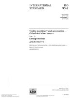
If required, calculate the modulus of elasticity, E, as shown in Equation (7).
Determine for each test piece the maximum slope of the force-elongation curve, Smax, expressed in newtons
per millimetre, using Equation (6).
⎛ ∆F ⎞
S max = ⎜
⎟
⎝ ∆δ ⎠ max
(6)
where
∆F is the force increment, in newtons;
∆δ is the elongation increment, in millimetres.
Using the mean maximum slope, S max , calculate the modulus of elasticity, E, expressed in megapascals,
from Equation (7).
E=
S max × l
b×t
(7)
where t is the thickness, in millimetres.
Report the modulus of elasticity to three significant figures.
7
© ISO 2008 – All rights reserved
--`,,```,,,,````-`-`,,`,,`,`,,`---
Copyright International Organization for Standardization
Provided by IHS under license with ISO
No reproduction or networking permitted without license from IHS
Not for Resale
--`,,```,,,,````-`-`,,`,,`,`,,`---
ISO 1924-2:2008(E)
Key
F
δ
tensile force
elongation
Smax maximum slope
∆F force increment
∆δ
elongation increment
Figure 2 — Concept used in the determination of the modulus of elasticity
10 Precision
10.1 General
The precision of the test depends on the variability of the paper or board being tested and the testing
equipment used.
Results of testing carried out independently in the Netherlands and the USA have been combined to produce
the data given in Table 1.
Results of testing carried out within Europe, compiled by the Confederation of European Paper Industries Comparative Testing Service (CEPI-CTS) are reported as repeatability and reproducibility data in Table 2 and
Table 3.
NOTE 1
s is the standard deviation.
NOTE 2
CV is the coefficient of variation.
10.2 Repeatability
Results from repeated measurements in the same laboratory are presented and reported as CV(within lab) in
Table 1 and as repeatability standard deviation, sr, and repeatability limit, r, in Tables 2 and 3.
10.3 Reproducibility
Results from measurements at different laboratories are presented and reported as CV(between labs) in
Table 1 and as reproducibility standard deviation, sR, and reproducibility limit, R, in Tables 2 and 3.
8
Copyright International Organization for Standardization
Provided by IHS under license with ISO
No reproduction or networking permitted without license from IHS
© ISO 2008 – All rights reserved
Not for Resale
ISO 1924-2:2008(E)
Table 1 — Repeatability and reproducibility data for tensile strength and strain at break
Mean CV(within lab)
Mean CV(between labs)
%
%
Tensile strength
5,8
Not known
2,9 kN/m to 11,5 kN/m
Tensile strength
3,8
12
0,7 % to 1,9 %
Strain at break
9,0
Not known
1,4 % to 2,6 %
Strain at break
6,6
30
2,3 % to 7,0 %
Strain at break
4,5
Not known
Tensile energy absorption
10
28
Test range
Method
0,5 kN/m to 1,3 kN/m
30
J/m2 to
200
J/m2
NOTE
The repeatability and reproducibility data originates from the previous edition of this part of ISO 1924 (ISO 1924-2:1994).
These data are largely based on the older technology of strip chart recorders and planimeters.
Range
Mean value
kN/m
sr
r
sR
R
kN/m
Number of
laboratories
kN/m
kN/m
kN/m
kN/m
1,30 to 1,70
1,50
19
0,06
0,166
0,06
0,235
4,50 to 5,50
5,00
18
0,23
0,637
0,18
0,810
6,50 to 7,50
7,00
18
0,23
0,637
0,24
0,921
11,0 to 12,5
11,75
19
0,65
1,801
0,50
2,273
NOTE
--`,,```,,,,````-`-`,,`,,`,`,,`---
Table 2 — Repeatability and reproducibility data for tensile strength
Results compiled by CEPI-CTS, 2006.
Table 3 — Repeatability and reproducibility data for strain at break
Range a
Mean value
%
sr
r
sR
R
%
Number of
laboratories
%
%
%
%
2,50 to 3,50
3,00
19
0,46
1,274
0,19
1,380
1,40 to 2,00
1,70
17
0,14
0,388
0,08
0,447
1,40 to 2,00
1,70
19
0,11
0,305
0,13
0,472
4,50 to 5,50
5,00
19
0,32
0,886
0,28
1,179
NOTE
a
Results compiled by CEPI-CTS, 2006.
The results from each sample are presented in the same order as in Table 2.
9
© ISO 2008 – All rights reserved
Copyright International Organization for Standardization
Provided by IHS under license with ISO
No reproduction or networking permitted without license from IHS
Not for Resale
ISO 1924-2:2008(E)
11 Test report
The test report shall include the following information:
a reference to this part of ISO 1924 (ISO 1924-2:2008);
b)
the date and place of testing;
c)
all the information necessary for complete identification of the sample;
d)
the conditioning atmosphere used;
e)
the direction of the test;
f)
the required results, as specified in Clause 9;
g)
the number of test pieces that break within 10 mm of the clamps;
h)
the standard deviation of required results;
i)
the grammage and thickness of the sample, if determined, and the pressure used for the measurement of
thickness;
j)
any departure from this part of ISO 1924 that may have affected the results.
--`,,```,,,,````-`-`,,`,,`,`,,`---
a)
10
Copyright International Organization for Standardization
Provided by IHS under license with ISO
No reproduction or networking permitted without license from IHS
© ISO 2008 – All rights reserved
Not for Resale
ISO 1924-2:2008(E)
Annex A
(normative)
Calibration of the tensile testing machine
Calibrate the force-measuring component of the machine, including the recording mechanism, if used, using
weights with masses known to an accuracy of ± 0,1 %. Calculate the force exerted as the product of the mass
of the weight and the local acceleration of free fall due to gravity. Alternatively, calibration rigs such as precalibrated elastic-proving devices may be used.
Calibrate, under load, the elongation-measuring mechanism of the tensile testing machine, including the
recording device, if used, throughout the required elongation range with either inside vernier callipers or gauge
blocks.
In some tensile testing machines, the force-measuring component may lengthen when loaded. To ensure that
this does not influence the results, calibrate both the force and the elongation-measuring components of the
instrument at several points within the relevant working range.
If an integrator is used with the machine in order to measure tensile energy absorption, calibrate it over the
relevant ranges of force and extension in accordance with the manufacturer's instructions.
Verify that the clamps are aligned to meet the requirements of 5.1.
Verify any plotting instrument used for the measurement of the modulus of elasticity.
11
© ISO 2008 – All rights reserved
Copyright International Organization for Standardization
Provided by IHS under license with ISO
No reproduction or networking permitted without license from IHS
Not for Resale
--`,,```,,,,````-`-`,,`,,`,`,,`---
The frequency of calibration cannot be prescribed since it is dependent on how often the tensile testing
machine is used. It is, however, recommended that the calibration be checked at monthly intervals as a
minimum.
ISO 1924-2:2008(E)
Bibliography
[1]
ISO 1924-3, Paper and board — Determination of tensile properties — Part 3: Constant rate of
elongation method (100 mm/min)
[2]
ISO 12625-4, Tissue paper and tissue products — Part 4: Determination of tensile strength, stretch at
break and tensile energy absorption
[3]
ISO 5270, Pulps — Laboratory sheets — Determination of physical properties
[4]
ISO 9513, Metallic materials — Calibration of extensometers used in uniaxial testing
--`,,```,,,,````-`-`,,`,,`,`,,`---
12
Copyright International Organization for Standardization
Provided by IHS under license with ISO
No reproduction or networking permitted without license from IHS
© ISO 2008 – All rights reserved
Not for Resale
--`,,```,,,,````-`-`,,`,,`,`,,`---
Copyright International Organization for Standardization
Provided by IHS under license with ISO
No reproduction or networking permitted without license from IHS
Not for Resale
--`,,```,,,,````-`-`,,`,,`,`,,`---
ISO 1924-2:2008(E)
ICS 85.060
Price based on 12 pages
© ISO 2008 – All rights reserved
Copyright International Organization for Standardization
Provided by IHS under license with ISO
No reproduction or networking permitted without license from IHS
Not for Resale