Tiêu chuẩn iso 00007 2 2000
Bạn đang xem bản rút gọn của tài liệu. Xem và tải ngay bản đầy đủ của tài liệu tại đây (330.25 KB, 38 trang )
ISO
7-2
INTERNATIONAL
STANDARD
Second edition
2000-09-15
Pipe threads where pressure-tight joints are
made on the threads —
Part 2:
Verification by means of limit gauges
Filetages de tuyauterie pour raccordement avec étanchéité dans le filet —
Partie 2: Vérification par calibres à limites
Reference number
ISO 7-2:2000(E)
© ISO 2000
Als Papierkopie - kein Änderungsdienst / Printed copy - no alert service
ISO 7-2:2000(E)
PDF disclaimer
This PDF file may contain embedded typefaces. In accordance with Adobe's licensing policy, this file may be printed or viewed but shall not
be edited unless the typefaces which are embedded are licensed to and installed on the computer performing the editing. In downloading this
file, parties accept therein the responsibility of not infringing Adobe's licensing policy. The ISO Central Secretariat accepts no liability in this
area.
Adobe is a trademark of Adobe Systems Incorporated.
Details of the software products used to create this PDF file can be found in the General Info relative to the file; the PDF-creation parameters
were optimized for printing. Every care has been taken to ensure that the file is suitable for use by ISO member bodies. In the unlikely event
that a problem relating to it is found, please inform the Central Secretariat at the address given below.
© ISO 2000
All rights reserved. Unless otherwise specified, no part of this publication may be reproduced or utilized in any form or by any means, electronic
or mechanical, including photocopying and microfilm, without permission in writing from either ISO at the address below or ISO's member body
in the country of the requester.
ISO copyright office
Case postale 56 · CH-1211 Geneva 20
Tel. + 41 22 749 01 11
Fax + 41 22 749 09 47
Web www.iso.ch
Printed in Switzerland
ii
© ISO 2000 – All rights reserved
Als Papierkopie - kein Änderungsdienst / Printed copy - no alert service
ISO 7-2:2000(E)
Contents
Page
Foreword.....................................................................................................................................................................iv
Introduction .................................................................................................................................................................v
1
Scope ..............................................................................................................................................................1
2
Normative reference ......................................................................................................................................1
3
Terms and definitions ...................................................................................................................................1
4
Symbols ..........................................................................................................................................................2
5
5.1
5.2
5.3
5.4
5.5
5.6
Design of gauges ...........................................................................................................................................3
General............................................................................................................................................................3
Taper full form threaded plug gauges (gauges No. 1 and No. 2)..............................................................4
Parallel full form threaded ring gauge (gauge No. 3) .................................................................................8
Taper plain ring gauge (gauge No. 4) ........................................................................................................10
Taper modified thread form check plug gauge (gauge No. 5) ................................................................11
Parallel modified thread form check ring gauge (gauge No. 6) ..............................................................13
6
6.1
6.2
6.3
Use of gauges and checking of pipe threads ...........................................................................................14
General..........................................................................................................................................................14
Checking of internal taper (Rc) and internal parallel (Rp) threads.........................................................15
Checking of external taper (R) threads .....................................................................................................16
7
Gauge dimensions and manufacturing tolerances, checking of new gauges and checking
gauges for wear ...........................................................................................................................................17
Gauge dimensions and manufacturing tolerances ..................................................................................17
Checking of new gauges.............................................................................................................................23
Checking gauges for wear ..........................................................................................................................26
Marking of gauges .......................................................................................................................................28
7.1
7.2
7.3
7.4
Annex A (normative) Summary of gauges..............................................................................................................29
© ISO 2000 – All rights reserved
Als Papierkopie - kein Änderungsdienst / Printed copy - no alert service
iii
ISO 7-2:2000(E)
Foreword
ISO (the International Organization for Standardization) is a worldwide federation of national standards bodies (ISO
member bodies). The work of preparing International Standards is normally carried out through ISO technical
committees. Each member body interested in a subject for which a technical committee has been established has
the right to be represented on that committee. International organizations, governmental and non-governmental, in
liaison with ISO, also take part in the work. ISO collaborates closely with the International Electrotechnical
Commission (IEC) on all matters of electrotechnical standardization.
International Standards are drafted in accordance with the rules given in the ISO/IEC Directives, Part 3.
Draft International Standards adopted by the technical committees are circulated to the member bodies for voting.
Publication as an International Standard requires approval by at least 75 % of the member bodies casting a vote.
Attention is drawn to the possibility that some of the elements of this part of ISO 7 may be the subject of patent
rights. ISO shall not be held responsible for identifying any or all such patent rights.
International Standard ISO 7-2 was prepared by Technical Committee ISO/TC 5, Ferrous metal pipes and metallic
fittings, Subcommittee SC 5, Threaded or plain end butt-welding fittings, gauging of threads.
This second edition cancels and replaces the first edition (ISO 7-2:1982), which has been technically revised.
ISO 7 consists of the following parts, under the general title Pipe threads where pressure-tight joints are made on
the threads:
¾
Part 1: Dimensions, tolerances and designation
¾
Part 2: Verification by means of limit gauges
Annex A forms a normative part of this part of ISO 7.
iv
© ISO 2000 – All rights reserved
Als Papierkopie - kein Änderungsdienst / Printed copy - no alert service
ISO 7-2:2000(E)
Introduction
This revision of ISO 7-2 has been undertaken with the aim of providing a unified gauging system which could be
adopted worldwide and thus eliminate the differing gauging results obtained with the use of gauges in accordance
with ISO 7-2:1982 and existing national practices. This revision also includes details of plain ring gauges to provide
additional means of checking ISO 7-1 external threads and a parallel modified thread form check ring gauge for
checking taper full form threaded plug gauges.
© ISO 2000 – All rights reserved
Als Papierkopie - kein Änderungsdienst / Printed copy - no alert service
v
Als Papierkopie - kein Änderungsdienst / Printed copy - no alert service
INTERNATIONAL STANDARD
ISO 7-2:2000(E)
Pipe threads where pressure-tight joints are made on the
threads —
Part 2:
Verification by means of limit gauges
1
Scope
This part of ISO 7 specifies a process using limit gauges, for the validation of taper internal and external threads
and parallel internal threads on piping systems components and other products, the dimensions and tolerances of
which are detailed in ISO 7-1.
The gauging system described may not be suitable, without special precautions, for gauging of threads on injection
moulded plastic workpieces.
This part of ISO 7 does not cover completely all the requirements necessary for full control of thread quality and
dimensions. Additional control of tools and equipment and visual inspection during production are required to
ensure complete compliance with ISO 7-1, for example the length of useful thread on internally threaded
workpieces should be checked by direct measurement.
Annex A gives a summary of the gauges included in this part of ISO 7, together with details of the thread elements
controlled by each gauge and gauge identification numbers.
In the event of a dispute over compliance with the requirements of ISO 7-1, the gauges in this part of ISO 7 are to
be considered as decisive for the thread elements which they control on the workpiece.
2
Normative reference
The following normative document contains provisions which, through reference in this text, constitute provisions of
this part of ISO 7. For dated references, subsequent amendments to, or revisions of, any of these publications do
not apply. However, parties to agreements based on this part of ISO 7 are encouraged to investigate the possibility
of applying the most recent edition of the normative document indicated below. For undated references, the latest
edition of the normative document referred to applies. Members of ISO and IEC maintain registers of currently valid
International Standards.
ISO 7-1:1994, Pipe threads where pressure-tight joints are made on the threads — Part 1: Dimensions, tolerances
and designation.
3
Terms and definitions
For the purposes of this part of ISO 7, the terms and definitions given in ISO 7-1 and the following apply.
3.1
accommodation length
distance from the face of an internally threaded workpiece to the first obstruction which the externally threaded
workpiece will encounter on assembly
See Figure 3.
© ISO 2000 – All rights reserved
Als Papierkopie - kein Änderungsdienst / Printed copy - no alert service
1
ISO 7-2:2000(E)
4
Symbols
The symbols used and their explanations are given in Table 1.
Table 1 — Symbols
2
Symbol
Explanation
b1
Width of clearance groove at major diameter of parallel full form threaded ring gauges and
minor diameter of taper full form threaded plug gauges
b2
Width of clearance groove at major diameter of parallel modified thread form check ring
gauges and at minor diameter of taper modified thread form check plug gauges
c
Height of tolerance step on plug gauges
D
Major diameter of internal thread at gauge plane
D1
Minor diameter of internal thread at gauge plane
D2
Pitch diameter of internal thread at gauge plane
D4
Counterbore diameter of parallel full form threaded ring gauge and taper plain ring gauge
d
Major diameter of external thread at gauge plane
d1
Minor diameter of external thread at gauge plane
d2
Pitch diameter of external thread at gauge plane
F
Radial distance from the pitch diameter to the truncated crest, along the centreline of the
thread profile
l0
Overall length of taper full form threaded plug gauge and taper modified thread form check
plug gauge
l1
Length from end face to the gauge plane on taper full form threaded plug gauge
l2
Length of tolerance step on plug gauges
l3
Overall length of parallel full form threaded ring gauge, parallel modified thread form check
ring gauge and length from gauge plane to small end of taper plain ring gauge
l4
Length of tolerance step on ring gauges
l5
Depth of counterbore on parallel full form threaded ring gauge
l6
Overall length of taper full form threaded plug gauge with relief
l7
Width of relief on taper full form threaded plug gauge with relief
l8
Length from relief on taper full form threaded plug gauge with relief to large end of gauge
l9
Overall length of taper plain ring gauge
l10
Depth of counterbore on taper plain ring gauge
l11
Distance from step on gauge Nos. 1 and 2 to face of gauge No. 6 when verifying pitch
diameter of new gauge Nos. 1 and 2
l12
Distance from step on gauge No. 5 to face of gauge No. 6 when verifying pitch diameter of
new gauge No. 6
l13
Distance from step on gauge Nos. 1 and 2 to face of gauge No. 6 when checking pitch
diameter of gauge Nos. 1 and 2 for wear
© ISO 2000 – All rights reserved
Als Papierkopie - kein Änderungsdienst / Printed copy - no alert service
ISO 7-2:2000(E)
Table 1 (concluded)
Symbol
Explanation
l14
Distance from step on gauge No. 5 to face of gauge No. 3 when checking pitch diameter of
gauge No. 3 for wear
P
Pitch
T= 1/2
Tolerance on flank angle of full form threads
T= 2/2
Tolerance on flank angle of modified form threads
TCP
Tolerance on pitch diameter for taper modified thread form check plug gauge and parallel
modified thread form check ring gauge
TP
Tolerance on pitch
TPL
Tolerance on pitch diameter and wear allowance for taper full form threaded plug gauges
TR
Tolerance on pitch diameter and wear allowance for parallel full form threaded ring gauge and
tolerance on diameter and wear allowance for taper plain ring gauge
T1
Tolerance on the gauge length of an external thread
T2
Tolerance on position of gauge plane on an internal thread
W
Permissible wear on diameter of all gauges except taper modified thread form check plug
gauges
NOTE
The values of D, D1, D2, d, d1 and d2 shown in Table 2 to Table 7 are basic values and are subject to the
manufacturing tolerances specified in clause 7.
5
5.1
Design of gauges
General
The taper full form threaded plug gauges and parallel full form threaded ring gauges (see 5.2 and 5.3) together with
the taper plain ring gauges (see 5.4) have been chosen as representing the requirements for mating components
or products within the tolerances of ISO 7-1.
Because of the 1:16 taper of the gauge and/or the threaded workpiece, it is possible to represent the maximum and
minimum limits of diameter by means of tolerance steps within the axial length of the gauges.
The plain ring gauges included in this part of ISO 7, allow a combined check of the major diameter and the length
of useful thread of externally threaded workpieces.
The taper modified thread form check plug gauge (see 5.5) and parallel modified thread form check ring gauge
(see 5.6) for checking the manufacturing tolerances and wear allowances for the parallel full form threaded ring
gauges and taper full form threaded plug gauges respectively, are made to a modified thread form.
Some dimensions given in this part of ISO 7 are more precise than the equivalent dimensions given in ISO 7-1.
This greater precision is only intended to assist the gauge manufacturing process and is of no practical significance
when using the gauges.
NOTE
The expression "full form" has been used to describe those threaded plug and ring gauges which may be full form or
alternatively have thread form relief at the discretion of the manufacturer, so as to differentiate from those threaded check plug
and check ring gauges which are always of modified thread form.
© ISO 2000 – All rights reserved
Als Papierkopie - kein Änderungsdienst / Printed copy - no alert service
3
ISO 7-2:2000(E)
5.2
5.2.1
Taper full form threaded plug gauges (gauges No. 1 and No. 2)
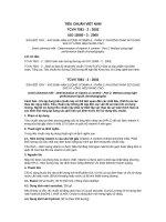
Taper full form threaded plug gauge (gauge No. 1)
This gauge is a 1:16 taper full form threaded plug gauge (see Figure 1) and is suitable for checking the major
diameter (D) and pitch diameter (D2) at the gauge plane of internal parallel (Rp) threads and internal taper (Rc)
threads.
Figure 1 — Taper full form threaded plug gauge (gauge No. 1)
The dimensions of this gauge are given in Table 2 and manufacturing tolerances are given in 7.1.1.2.
The gauge incorporates a step equal in length to the total tolerance T2 on the position of the gauge plane of the
internal thread specified in ISO 7-1. To allow for the chamfer on the internal thread, the step is displaced by 0,5P
relative to the gauge plane, such that the internally threaded workpiece can be verified with reference to its face.
The large diameter end face of the gauge is marked '+' (positive) and the face of the tolerance step is marked '–'
(negative).
NOTE
4
For sizes smaller than 1/2, the '+' and '–' markings may be omitted if not practicable.
© ISO 2000 – All rights reserved
Als Papierkopie - kein Änderungsdienst / Printed copy - no alert service
ISO 7-2:2000(E)
Table 2 — Dimensions of taper full form threaded plug gauge (gauge No. 1)
Dimensions in millimetres
Diameters at gauge plane
Designation
of thread
Pitch
major
Pitch
minor
Overall
length of
gauge
Length
from end
face to the
gauge
plane
Length of
tolerance
step
P
d, D
d2, D2
d1, D1
l0
l1
l2
Width of
clearance
groove
Height
of step
b1
c
max.
1
2
3
4
5
1/16
0,907
7,723
7,142
6,561
1/8
0,907
9,728
9,147
1/4
1,337
13,157
3/8
1,337
1/2
6
7
8
9
10
5,6
1,588
2,268
0,3
1,8
8,566
5,6
1,588
2,268
0,3
1,8
12,301
11,445
8,4
2,339
3,342
0,4
2,4
16,662
15,806
14,950
8,8
2,339
3,342
0,4
2,4
1,814
20,955
19,793
18,631
11,4
3,175
4,536
0,5
3,3
3/4
1,814
26,441
25,279
24,117
12,7
3,175
4,536
0,5
4,5
1
2,309
33,249
31,770
30,291
14,5
4,041
5,773
0,6
5,8
1 1/4
2,309
41,910
40,431
38,952
14,5
4,041
5,773
0,6
5,8
1 1/2
2,309
47,803
46,324
44,845
14,5
4,041
5,773
0,6
5,8
2
2,309
59,614
58,135
56,656
15
4,041
5,773
0,6
5,8
2 1/2
2,309
75,184
73,705
72,226
17,5
4,618
6,927
0,6
6,9
3
2,309
87,884
86,405
84,926
18,5
4,618
6,927
0,6
6,9
4
2,309
113,030
111,551
110,072
20
4,618
6,927
0,6
6,9
5
2,309
138,430
136,951
135,472
24
4,618
6,927
0,6
10
6
2,309
163,830
162,351
160,872
24
4,618
6,927
0,6
10
NOTE
The values given in columns 3, 4 and 5 are basic values intended for the calculation of diameters at the gauge
plane in accordance with 7.1.1.
5.2.2
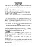
Taper full form threaded plug gauge with relief (gauge No. 2)
This gauge is a 1:16 taper full form threaded plug gauge with relief of threads (see Figure 2) and is suitable for
checking the major diameter (D) and pitch diameter (D2) at the gauge plane, and the accommodation length (see
Figure 3) of internal parallel (Rp) threads and internal taper (Rc) threads.
© ISO 2000 – All rights reserved
Als Papierkopie - kein Änderungsdienst / Printed copy - no alert service
5
ISO 7-2:2000(E)
Figure 2 — Taper full form threaded plug gauge with relief (gauge No. 2)
NOTE
Figure 3 is applicable to internal parallel (Rp) threads and internal taper (Rc) threads.
Figure 3 — Accommodation length
The dimensions of this gauge are given in Table 3 and manufacturing tolerances are given in 7.1.1.2.
The gauge incorporates a step equal in length to the total tolerance T2 on the position of the gauge plane of the
internal thread specified in ISO 7-1. To allow for the chamfer on the internal thread, the step is displaced by 0,5P
relative to the gauge plane, such that the internally threaded workpiece can be checked with reference to its face.
On sizes 1/4 and larger, a thread relief is provided part way along the gauge, thereby reducing the number of
threads and consequential friction in contact with the internally threaded workpiece.
The overall length (l6) of the gauge is equal to the length of useful thread for maximum gauge length plus 0,5P.
The large diameter end face of the gauge is marked '+' (positive) and the face of the tolerance step is marked '–'
(negative).
NOTE
6
For sizes smaller than 1/2, the '+' and '–' markings may be omitted if not practicable.
© ISO 2000 – All rights reserved
Als Papierkopie - kein Änderungsdienst / Printed copy - no alert service
ISO 7-2:2000(E)
Table 3 — Dimensions of taper full form threaded plug gauge with relief (gauge No. 2)
Dimensions in millimetres
Diameters at gauge plane
Designation
of thread
Pitch
major
pitch
Minor
Length
from end
face to
the gauge
plane
Length of
tolerance
step
P
d, D
d2, D2
d1, D1
l1
l2
Overall Width of Length from Width of
Length of
relief
relief to
clearance
gauge
large end of
groove
gauge
l6
l7
l8
b1
Height of
step
c
max.
1
2
3
4
1/16
0,907
7,723
7,142
1/8
0,907
9,728
1/4
1,337
3/8
5
6
7
6,561
1,588
2,268
9,147
8,566
1,588
13,157
12,301
11,445
1,337
16,662
15,806
1/2
1,814
20,955
3/4
1,814
1
8
9
10
11
12
7,823
—
—
0,3
1,8
2,268
7,823
—
—
0,3
1,8
2,339
3,342
11,699
2,3
5,3
0,4
2,4
14,950
2,339
3,342
12,033
2,7
5,3
0,4
2,4
19,793
18,631
3,175
4,536
15,872
3,2
7,3
0,5
3,3
26,441
25,279
24,117
3,175
4,536
17,233
4,5
7,3
0,5
4,5
2,309
33,249
31,770
30,291
4,041
5,773
20,204
4,1
9,2
0,6
5,8
1 1/4
2,309
41,910
40,431
38,952
4,041
5,773
22,513
6,4
9,2
0,6
5,8
1 1/2
2,309
47,803
46,324
44,845
4,041
5,773
22,513
6,4
9,2
0,6
5,8
2
2,309
59,614
58,135
56,656
4,041
5,773
26,842
10,7
9,2
0,6
5,8
2 1/2
2,309
75,184
73,705
72,226
4,618
6,927
31,316
14
10,4
0,6
6,9
3
2,309
87,884
86,405
84,926
4,618
6,927
34,491
17,1
10,4
0,6
6,9
4
2,309
113,030 111,551 110,072
4,618
6,927
40,407
23,1
10,4
0,6
6,9
5
2,309
138,430 136,951 135,472
4,618
6,927
44,737
27,4
10,4
0,6
10
6
2,309
163,830 162,351 160,872
4,618
6,927
44,737
27,4
10,4
0,6
10
NOTE The values given in columns 3, 4 and 5 are basic values intended for the calculation of diameters at the gauge
plane in accordance with 7.1.1.
© ISO 2000 – All rights reserved
Als Papierkopie - kein Änderungsdienst / Printed copy - no alert service
7
ISO 7-2:2000(E)
5.3
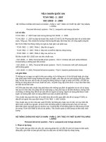
Parallel full form threaded ring gauge (gauge No. 3)
This gauge is a parallel full form threaded ring gauge (see Figure 4) and is suitable for checking the minor diameter
(d1) and pitch diameter (d2) at the gauge plane of taper external (R) threads.
Figure 4 — Parallel full form threaded ring gauge (gauge No. 3)
The dimensions of this gauge are given in Table 4 and manufacturing tolerances are given in 7.1.1.2.
The gauge incorporates a step equal to the total tolerance T1 on gauge length, specified in ISO 7-1. The step is
situated between minimum and maximum gauge lengths measured from the gauge plane and is counterbored for
the diameter D4 to a depth l5.
The gauge plane is located at the face of the gauge, opposite to the step.
The overall length (l3) of the gauge corresponds to the maximum gauge length.
The outer and inner faces of the tolerance step shall be marked '+' (positive) and '–' (negative) respectively.
NOTE
These signs indicate the maximum and minimum gauge lengths, respectively the corresponding minimum and
maximum allowable diameters of the external thread.
8
© ISO 2000 – All rights reserved
Als Papierkopie - kein Änderungsdienst / Printed copy - no alert service
ISO 7-2:2000(E)
Table 4 — Dimensions of parallel full form threaded ring gauge (gauge No. 3)
Dimensions in millimetres
Diameters at gauge plane
Designation
of thread
Pitch
major
pitch
minor
P
D, d
D2, d2
D1, d1
Width of
clearance
groove
Diameter of
counterbore
Overall
length of
gauge
Length of
tolerance
step
Depth of
counterbore
b1
D4
l3
l4
l5
6
7
8
9
10
max.
1
2
3
4
5
1/16
0,907
7,723
7,142
6,561
0,3
9,5
4,876
1,814
2
1/8
0,907
9,728
9,147
8,566
0,3
11,5
4,876
1,814
2
1/4
1,337
13,157
12,301
11,445
0,4
15,5
7,353
2,674
3
3/8
1,337
16,662
15,806
14,950
0,4
19
7,687
2,674
3,2
1/2
1,814
20,955
19,793
18,631
0,5
23,5
9,979
3,628
4,1
3/4
1,814
26,441
25,279
24,117
0,5
29
11,339
3,628
4,6
1
2,309
33,249
31,770
30,291
0,6
36
12,700
4,618
5,3
1 1/4
2,309
41,910
40,431
38,952
0,6
44,5
15,009
4,618
6,4
1 1/2
2,309
47,803
46,324
44,845
0,6
50,5
15,009
4,618
6,4
2
2,309
59,614
58,135
56,656
0,6
62
18,184
4,618
8
2 1/2
2,309
75,184
73,705
72,226
0,6
77,5
20,926
6,927
9,2
3
2,309
87,884
86,405
84,926
0,6
90,5
24,101
6,927
10,4
4
2,309
113,030
111,551
110,072
0,6
115,5
28,864
6,927
12,8
5
2,309
138,430
136,951
135,472
0,6
141
32,039
6,927
14,4
6
2,309
163,830
162,351
160,872
0,6
166,5
32,039
6,927
14,4
NOTE
The values given in columns 3, 4 and 5 are basic values intended for the calculation of diameters at the gauge
plane in accordance with 7.1.1.
© ISO 2000 – All rights reserved
Als Papierkopie - kein Änderungsdienst / Printed copy - no alert service
9
ISO 7-2:2000(E)
5.4
Taper plain ring gauge (gauge No. 4)
This gauge is a 1:16 taper plain ring gauge (see Figure 5) and is suitable for checking the major diameter (d) and
the related useful thread length on taper external (R) threads.
The dimensions of this gauge are given in Table 5 and manufacturing tolerances are given in 7.1.2.
The gauge incorporates a step equal in length to the total tolerance (T1 ) on gauge length, specified in ISO 7-1. The
step is situated between minimum and maximum gauge lengths measured from the gauge plane.
The overall length (l9) of the gauge corresponds to the length of useful thread for maximum gauge length.
The small diameter end face of the gauge is marked '+' (positive) and the face of the tolerance step is marked '–'
(negative).
NOTE
These signs indicate the maximum and minimum gauge lengths, respectively the corresponding minimum and
maximum allowable major diameters of the external thread.
Figure 5 — Taper plain ring gauge (gauge No. 4)
10
© ISO 2000 – All rights reserved
Als Papierkopie - kein Änderungsdienst / Printed copy - no alert service
ISO 7-2:2000(E)
Table 5 — Dimensions of taper plain ring gauge (gauge No. 4)
Dimensions in millimetres
Designation of
thread
Diameter at
gauge plane
Diameter of
counterbore
Length from
gauge plane
to small end
of gauge
Length of
tolerance step
Overall length
of gauge
Depth of
counterbore
d
D4
l3
l4
l9
l10
1
2
3
4
5
6
7
1/16
7,723
9,5
4,876
1,814
7,369
2,3
1/8
9,728
11,5
4,876
1,814
7,369
2,3
1/4
13,157
15,5
7,353
2,674
11,030
3,3
3/8
16,662
19
7,687
2,674
11,364
3,3
1/2
20,955
23,5
9,979
3,628
14,965
4,5
3/4
26,441
29
11,339
3,628
16,326
4,5
1
33,249
36
12,700
4,618
19,049
5,8
1 1/4
41,910
44,5
15,009
4,618
21,358
5,8
1 1/2
47,803
50,5
15,009
4,618
21,358
5,8
2
59,614
62
18,184
4,618
25,688
5,8
2 1/2
75,184
77,5
20,926
6,927
30,161
8,1
3
87,884
90,5
24,101
6,927
33,336
8,1
4
113,030
115,5
28,864
6,927
39,253
8,1
5
138,430
141
32,039
6,927
43,582
8,1
6
163,830
166,5
32,039
6,927
43,582
8,1
NOTE The values given in column 2 are basic values intended for the calculation of diameters at the gauge plane in
accordance with 7.1.2.
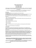
5.5
Taper modified thread form check plug gauge (gauge No. 5)
This check plug gauge (see Figure 6) is used to check the dimensions of the parallel threaded ring gauge (gauge
No. 3) when manufacturing the ring gauge and for checking the ring gauge for wear.
The gauge is designed on the basis of the taper threaded plug gauge (gauge No. 1). The tolerance step has been
retained, but with respect to the gauge plane it is positioned entirely in the plus tolerance zone.
The threads of the check plug gauge are truncated at the crests and provided with a clearance groove at the root of
the thread in order to ensure the pitch diameters engage when gauging is carried out.
The dimensions of this check plug gauge are given in Table 6.
© ISO 2000 – All rights reserved
Als Papierkopie - kein Änderungsdienst / Printed copy - no alert service
11
ISO 7-2:2000(E)
Figure 6 — Taper modified thread form check plug gauge (gauge No. 5)
Table 6 — Dimensions of taper modified thread form check plug gauge (gauge No. 5)
Dimensions in millimetres
Diameters at gauge plane
Designation of
thread
Pitch
major
pitch
minor
Width of
clearance
groove
Height of
step
Overall
length
of gauge
Length of
tolerance
step
Radial
distance from
pitch diameter
to truncated crest
P
d, D
d2, D2
d1, D1
b2
c
l0
l2
F
1
2
3
4
5
6
7
8
9
10
1/16
0,907
7,723
7,142
6,561
0,3
1,8
5,6
2,268
0,145
1/8
0,907
9,728
9,147
8,566
0,3
1,8
5,6
2,268
0,145
1/4
1,337
13,157
12,301
11,445
0,4
2,4
8,4
3,342
0,214
3/8
1,337
16,662
15,806
14,950
0,4
2,4
8,8
3,342
0,214
1/2
1,814
20,955
19,793
18,631
0,5
3,3
11,4
4,536
0,290
3/4
1,814
26,441
25,279
24,117
0,5
4,5
12,7
4,536
0,290
1
2,309
33,249
31,770
30,291
0,8
5,8
14,5
5,773
0,369
1 1/4
2,309
41,910
40,431
38,952
0,8
5,8
14,5
5,773
0,369
1 1/2
2,309
47,803
46,324
44,845
0,8
5,8
14,5
5,773
0,369
2
2,309
59,614
58,135
56,656
0,8
5,8
15
5,773
0,369
2 1/2
2,309
75,184
73,705
72,226
0,8
6,9
17,5
6,927
0,369
3
2,309
87,884
86,405
84,926
0,8
6,9
18,5
6,927
0,369
4
2,309
113,030
111,551
110,072
0,8
6,9
20
6,927
0,369
5
2,309
138,430
136,951
135,472
0,8
10
24
6,927
0,369
6
2,309
163,830
162,351
160,872
0,8
10
24
6,927
0,369
NOTE The values given in columns 3, 4 and 5 are basic values intended for the calculation of diameters at the gauge
plane in accordance with 7.1.3.
12
© ISO 2000 – All rights reserved
Als Papierkopie - kein Änderungsdienst / Printed copy - no alert service
ISO 7-2:2000(E)
5.6
Parallel modified thread form check ring gauge (gauge No. 6)
This check ring gauge (see Figure 7) is provided to check the dimensions of the taper full form threaded plug
gauges (gauge Nos. 1 and 2) when manufacturing the plug gauges and for checking the plug gauges for wear.
NOTE
The use of gauge No. 6 when manufacturing gauge Nos. 1 and 2 is at the discretion of the gauge manufacturer. The
use of gauge No. 6 for checking gauge Nos. 1 and 2 for wear is at the discretion of the gauge user.
The gauge is designed on the basis of the parallel full form threaded ring gauge (gauge No. 3) except that there is
no tolerance step.
The threads of the check ring gauge are truncated at the crests and provided with a clearance groove at the root of
the thread to ensure the pitch diameters engage when gauging is carried out.
The dimensions of the check ring gauge are given in Table 7.
One face of the gauge is marked to indicate the position of the gauge plane. This marking shall be "Gauge plane"
or some other words or symbols agreed between the gauge manufacturer and the purchaser.
Figure 7 — Parallel modified thread form check ring gauge (gauge No. 6)
© ISO 2000 – All rights reserved
Als Papierkopie - kein Änderungsdienst / Printed copy - no alert service
13
ISO 7-2:2000(E)
Table 7 — Dimensions of parallel modified thread form check ring gauge (gauge No. 6)
Dimensions in millimetres
Diameters at gauge plane
Designation
of thread
Pitch
major
pitch
minor
Width of
clearance
groove
Overall
length of
gauge
Radial distance
from pitch
diameter to
truncated crest
P
d, D
d2, D2
d1, D1
b2
l3
F
1
2
3
4
5
6
7
8
1/16
0,907
7,723
7,142
6,561
0,3
4,8
0,145
1/8
0,907
9,728
9,147
8,566
0,3
4,8
0,145
1/4
1,337
13,157
12,301
11,445
0,4
7,3
0,214
3/8
1,337
16,662
15,806
14,950
0,4
7,6
0,214
1/2
1,814
20,955
19,793
18,631
0,5
9,9
0,290
3/4
1,814
26,441
25,279
24,117
0,5
11,3
0,290
1
2,309
33,249
31,770
30,291
0,8
12,7
0,369
1 1/4
2,309
41,910
40,431
38,952
0,8
15
0,369
1 1/2
2,309
47,803
46,324
44,845
0,8
15
0,369
2
2,309
59,614
58,135
56,656
0,8
18,1
0,369
2 1/2
2,309
75,184
73,705
72,226
0,8
20,9
0,369
3
2,309
87,884
86,405
84,926
0,8
24,1
0,369
4
2,309
113,030
111,551
110,072
0,8
28,8
0,369
5
2,309
138,430
136,951
135,472
0,8
32
0,369
6
2,309
163,830
162,351
160,872
0,8
32
0,369
NOTE The values given in columns 3, 4 and 5 are basic values intended for the calculation of diameters at the gauge plane
in accordance with 7.1.4.
6
6.1
Use of gauges and checking of pipe threads
General
The gauging system described provides methods by which the requirements specified in ISO 7-1 can be controlled
and checked, when used in conjunction with other means (not defined in this part of ISO 7) of controlling and
checking the correctness of other thread elements.
NOTE
Failure to control those thread elements which require checking by other means could adversely affect the gauging
results obtained with this system.
It is intended that the full range of appropriate gauges is used when inspecting the threaded workpiece. The full
range of gauges is shown in annex A. In the event of a dispute, the acceptance or rejection of the workpiece shall
be based on the use of all appropriate gauges.
The gauging system described is equally applicable to parallel and taper internally threaded workpieces.
14
© ISO 2000 – All rights reserved
Als Papierkopie - kein Änderungsdienst / Printed copy - no alert service