Tiêu chuẩn iso 04586 2 2004
Bạn đang xem bản rút gọn của tài liệu. Xem và tải ngay bản đầy đủ của tài liệu tại đây (1.44 MB, 76 trang )
INTERNATIONAL
STANDARD
ISO
4586-2
Fifth edition
2004-10-15
High-pressure decorative laminates —
Sheets made from thermosetting
resins —
Part 2:
Determination of properties
Stratifiés décoratifs haute pression — Plaques à base de résines
thermodurcissables —
Partie 2: Détermination des caractéristiques
Reference number
ISO 4586-2:2004(E)
© ISO 2004
ISO 4586-2:2004(E)
PDF disclaimer
This PDF file may contain embedded typefaces. In accordance with Adobe's licensing policy, this file may be printed or viewed but shall
not be edited unless the typefaces which are embedded are licensed to and installed on the computer performing the editing. In
downloading this file, parties accept therein the responsibility of not infringing Adobe's licensing policy. The ISO Central Secretariat
accepts no liability in this area.
Adobe is a trademark of Adobe Systems Incorporated.
Details of the software products used to create this PDF file can be found in the General Info relative to the file; the PDF-creation
parameters were optimized for printing. Every care has been taken to ensure that the file is suitable for use by ISO member bodies. In the
unlikely event that a problem relating to it is found, please inform the Central Secretariat at the address given below.
© ISO 2004
All rights reserved. Unless otherwise specified, no part of this publication may be reproduced or utilized in any form or by any means,
electronic or mechanical, including photocopying and microfilm, without permission in writing from either ISO at the address below or
ISO's member body in the country of the requester.
ISO copyright office
Case postale 56 • CH-1211 Geneva 20
Tel. + 41 22 749 01 11
Fax + 41 22 749 09 47
Web www.iso.org
Published in Switzerland
ii
© ISO 2004 – All rights reserved
ISO 4586-2:2004(E)
Contents
Page
1
Scope ....................................................................................................................................................
2
Normative references ..........................................................................................................................
1
3
Terms and definitions ..........................................................................................................................
2
4
Thickness .............................................................................................................................................
2
5
Appearance ..........................................................................................................................................
2
6
Resistance to surface wear ................................................................................................................
4
7
Resistance to immersion in boiling water .........................................................................................
7
8
Resistance to dry heat ........................................................................................................................
9
9
Resistance to wet heat ......................................................................................................................
10
10
Resistance to steam ..........................................................................................................................
12
11
Dimensional stability .........................................................................................................................
14
12
Resistance to impact by small-diameter ball ..................................................................................
19
13
Resistance to impact by large-diameter ball ...................................................................................
23
14
Resistance to cracking under stress (thin laminates ) ...................................................................
26
15
Resistance to scratching ..................................................................................................................
30
16
Resistance to staining .......................................................................................................................
36
17
Lightfastness .....................................................................................................................................
43
18
Resistance to cigarette burns ...........................................................................................................
48
19
Formability .........................................................................................................................................
57
20
Resistance to blistering ....................................................................................................................
64
21
Resistance to crazing of compact laminates ..................................................................................
68
22
Resistance to moisture of double-faced compact laminates ........................................................
69
Bibliography ...............................................................................................................................................
71
© ISO 2004 – All rights reserved
1
iii
ISO 4586-2:2004(E)
Foreword
ISO (the International Organization for Standardization) is a worldwide federation of national standards bodies
(ISO member bodies). The work of preparing International Standards is normally carried out through ISO
technical committees. Each member body interested in a subject for which a technical committee has been
established has the right to be represented on that committee. International organizations, governmental and
non-governmental, in liaison with ISO, also take part in the work. ISO collaborates closely with the International
Electrotechnical Commission (IEC) on all matters of electrotechnical standardization.
International Standards are drafted in accordance with the rules given in the ISO/IEC Directives, Part 2.
The main task of technical committees is to prepare International Standards. Draft International Standards
adopted by the technical committees are circulated to the member bodies for voting. Publication as an
International Standard requires approval by at least 75 % of the member bodies casting a vote.
Attention is drawn to the possibility that some of the elements of this document may be the subject of patent
rights. ISO shall not be held responsible for identifying any or all such patent rights.
ISO 4586-2 was prepared by Technical Committee ISO/TC 61, Plastics, Subcommittee SC 11, Products.
This fifth edition cancels and replaces the fourth edition (ISO 4586-2:1997), of which it constitues a minor
revision intended
a) to combine the 1997 edition with its amendments (Amendments 3 to 8) to give a single document;
b) to reintroduce a previously deleted method (determination of resistance to colour change in light from an
enclosed carbon-arc lamp) (see 17.3).
ISO 4586 consists of the following parts, under the general title High-pressure decorative laminates — Sheets
made from thermosetting resins:
— Part 1: Classification and specifications
— Part 2: Determination of properties
iv
© ISO 2004 – All rights reserved
INTERNATIONAL STANDARD
ISO 4586-2:2004(E)
High-pressure decorative laminates — Sheets made from
thermosetting resins —
Part 2:
Determination of properties
1 Scope
This part of ISO 4586 specifies methods of test for determination of the properties of high-pressure decorative
laminated sheets as defined in Clause 3. These methods are primarily intended for testing the sheets specified
in ISO 4586-1.
The precision of the test methods specified in Clauses 4, 7 and 11 of this part of ISO 4586 is not known
because inter-laboratory data are not available. When inter-laboratory data are obtained, precision statements
will be added to the test methods at the following revision. As all the other test methods have an end point
determination based on subjective judgement, it is not meaningful to make a statement of precision in these
cases.
2 Normative references
The following referenced documents are indispensable for the application of this document. For dated
references, only the edition cited applies. For undated references, the latest edition of the referenced document
(including any amendments) applies.
ISO 105-A02, Textiles — Tests for colour fastness — Part A02: Grey scale for assessing change in colour
ISO 105-B02, Textiles — Tests for colour fastness — Part B02: Colour fastness to artificial light: Xenon arc
fading lamp test
ISO 4211-3, Furniture — Tests for surface finishes — Part 3: Assessment of resistance to dry heat
ISO 4586-1:2004, High-pressure decorative laminates — Sheets made from thermosetting resins — Part 1:
Classification and specification
ISO 4892:1981, Plastics — Methods of exposure to laboratory light sources1)
ISO 4892-1, Plastics — Methods of exposure to laboratory light sources — Part 1: General guidance
ISO 4892-2:1994, Plastics — Methods of exposure to laboratory light sources — Part 2: Xenon-arc sources
ISO 6506-1, Metallic materials — Brinell hardness test — Part 1: Test method
ISO 9352, Plastics — Determination of resistance to wear by abrasive wheels
ISO 9370, Plastics — Instrumental determination of radiant exposure in weathering tests — General guidance
and basic test method
CIE Publication No. 85:1989, Solar spectral irradiance
1) Withdrawn, but still used in certain Asian countries.
© ISO 2004 – All rights reserved
1
ISO 4586-2:2004(E)
3 Terms and definitions
For the purposes of this document, the definition of high-pressure decorative laminate(s) given in 3.1 of
ISO 4586-1:2004 applies.
The abbreviation “HPDL” for high-pressure decorative laminate(s) is used in ISO 4586. It should be noted that
the abbreviation “HPL” is frequently used instead of “HPDL”, and the term “HPL” in the European standard
EN 438 is equivalent to “HPDL” in ISO 4586.
4 Thickness
4.1 Principle
The thickness of a sheet is measured using a micrometer or a dial gauge indicator.
4.2 Apparatus
4.2.1 Thickness gauge (ratchet-type micrometer or dial gauge indicator), having two flat parallel measuring
surfaces of diameter at least 6 mm and capable of being read to 0,01 mm. When the thickness of a decorative
laminated sheet is being measured, the two surfaces shall exert a pressure of 10 kPa to 100 kPa upon each
other.
4.3 Test specimen
The specimen shall be the sheet under test, as received.
4.4 Procedure
Check the gauge for accuracy and then determine the thickness of the sheet to the nearest 0,02 mm. It is
recommended that the thickness be measured at a minimum of four points and at a distance of at least 20 mm
from the edge of the sheet.
4.5 Test report
The test report shall include the following information:
a) a reference to this part of ISO 4586;
b) the name and type of product;
c) all values measured;
d) the location of the points at which measurements were made;
e) any deviation from the specified test method;
f)
the date of the test.
5 Appearance
5.1 Surface defects
5.1.1 Principle
Sheets are inspected for surface appearance under standardized conditions of lighting and viewing.
2
© ISO 2004 – All rights reserved
ISO 4586-2:2004(E)
5.1.2 Apparatus
5.1.2.1 Horizontal inspection table, of height approximately 700 mm and large enough to accommodate the
largest sheets to be inspected.
5.1.2.2 Overhead white fluorescent lights, of colour temperature approximately 5 000 K and giving an
intensity of 800 lx to 1 000 lx over the whole area of the largest sheets to be inspected. A convenient distance of
the lights from the inspection table is approximately 1,5 m.
5.1.3 Test specimen
The specimen shall be the sheet under test, as received.
5.1.4 Procedure
Place the sheet, decorative face uppermost, on the inspection table. Wipe it free of any loose contamination, if
necessary, with a soft cloth. Inspect it from the distance required by ISO 4586-1:2004 for defects such as
smudges, smears, fingerprints, scratches, foreign particles, damage or any other form of blemish evident within
the decorative surface.
The inspector shall use normal vision, corrected if necessary. No magnifying glass shall be used in viewing the
sheet.
5.1.5 Test report
The test report shall include the following information:
a) a reference to this part of ISO 4586;
b) the name and type of product;
c) the viewing distance and any defects observed;
d) any deviation from the specified test method;
e) the date of the test.
5.2 Flatness
5.2.1 Apparatus
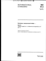
5.2.1.1 Straightedge, of 1 000 mm length, with optional dial gauge (see Figure 1).
5.2.2 Test specimen
The specimen shall be the sheet under test, as received, stored in the conditions recommended by the
manufacturer.
5.2.3 Procedure
Place the sheet under test, concave side up, on a flat surface. Measure the departure between the straightedge
and the concave surface of the laminate at the point of maximum curvature.
© ISO 2004 – All rights reserved
3
ISO 4586-2:2004(E)
Key
1
2
dial gauge
straightedge
3
4
laminate
flat surface
h
distance between the straightedge and the surface of the laminate
Figure 1 — Example of equipment for measuring flatness (see 5.2.1)
5.2.4 Test report
The test report shall include the following information:
a) a reference to this part of ISO 4586;
b) the name and type of product;
c) the maximum deviation, in millimetres;
d) any deviation from the specified test method;
e) the date of the test.
6 Resistance to surface wear
6.1 Principle
The test measures the ability of the decorative surface of the sheet under test to resist abrasive wear-through to
the sub-layer. Abrasion is achieved by rotating a specimen in contact with a pair of loaded cylindrical wheels
covered with abrasive paper. The wheels are positioned so that their cylindrical faces are equidistant from the
specimen's axis of rotation but not tangential to it. As they are turned by the rotating specimen, they abrade an
annular track on the specimen's surface. The numbers of revolutions of the specimen required to cause defined
degrees of abrasion are used as measures of resistance to surface wear.
6.2 Materials
6.2.1 Calibration plates of rolled zinc sheet (Taber S-34 or equivalent), having a thickness of
0,8 mm ± 0,1 mm and a Brinell hardness of 48 ± 2 when tested in accordance with ISO 6506-1, except that
the ball diameter shall be 5 mm and the load 360 N.
4
© ISO 2004 – All rights reserved
ISO 4586-2:2004(E)
6.2.2 Abrasive paper strips (Taber S-42 or equivalent), of width 12,7 mm ± 0,1 mm and length about
160 mm, having the following composition:
a) paper of grammage 70 g/m2 to 100 g/m2 ;
b) open coated 180 grit powdered aluminium oxide (Al2O3) having a particle size such that it will pass through
a sieve of aperture 100 µm and remain on a sieve having an aperture of 63 µm;
c) adhesive backing (optional).
6.2.3 Double-sided adhesive tape, required only if the abrasive paper has no adhesive backing.
6.3 Apparatus
6.3.1 Test machine, as specified in ISO 9352.
NOTE A suitable machine is available from Taber Acquisition Corp., Taber Industries, 455 Bryant St, P.O. Box 164, North
Tonawanda, NY 14120, USA. This is an example of a suitable product available commercially. This information is given for
the convenience of users of this part of ISO 4586 and does not constitute an endorsement by ISO of this product.
6.3.2 Conditioning chamber, with a standard atmosphere of 23 ◦ C ± 2 ◦ C, relative humidity of (50 ± 5) %.
6.4 Test specimens
Each specimen shall be a piece of the sheet under test, shaped to fit the type of clamping device used. It will
usually be a disc of diameter about 130 mm, or a square of side about 120 mm with its corners rounded to give
a diagonal of about 130 mm, and it will usually have a hole of diameter 6 mm in its centre. Three specimens
shall be prepared.
6.5 Preparation of specimens and abrasive paper
Clean the surface of the specimens with a non-hazardous organic solvent which is immiscible with water. Using
a suitable marker pen, mark the surface of each specimen with two lines at right angles to each other so that the
surface area is divided into quadrants. Precondition the specimens and the abrasive strips for at least 72 h in
the conditioning atmosphere (see 6.3.2) before testing. After preconditioning, seal the paper strips in suitable
polyethylene bags (maximum 10 strips per bag) until required for immediate use.
6.6 Procedure
6.6.1 Preparation of abrasive wheels
Bond a strip of preconditioned unused abrasive paper (6.2.2) to each of the rubber-covered wheels, using either
the adhesive backing, if present, or the double-sided adhesive tape (6.2.3), in such a way that the cylindrical
surface is completely covered, but without any overlapping of the abrasive paper.
6.6.2 Calibration of abrasive paper
Prepare two abrasive wheels with preconditioned unused strips of abrasive paper from the batch to be used for
testing (see 6.6.1).
Clamp a zinc plate (6.2.1) in the specimen holder, start the suction device, set the revolution-counter to zero,
lower the wheels and abrade the zinc plate for 500 revolutions. Wipe the zinc plate clean and weigh to the
nearest 1 mg. Replace the abrasive paper on the wheels with preconditioned unused strips from the same
batch, clamp the same zinc plate in the specimen holder, lower the abrasive wheels and operate the suction
device. Abrade the zinc plate for an additional 500 revolutions, then wipe it clean and reweigh it to the nearest
1 mg. Its loss in mass shall be 130 mg ± 20 mg.
© ISO 2004 – All rights reserved
5
ISO 4586-2:2004(E)
Any batch of abrasive paper which causes a loss in mass of the zinc plate outside this permitted range shall not
be used for testing.
6.6.3 Abrasion of specimen
Perform the test immediately after removal of the specimen and calibrated abrasive paper from the
preconditioning atmosphere.
Prepare two wheels with preconditioned unused abrasive paper from the same batch previously approved by
calibration. Fit the wheels to the machine and set the revolution counter to zero.
Clamp the specimen in the holder, ensuring that its surface is flat. Lower the abrasive wheels on to the
specimen, start the suction device and begin abrading the specimen. Examine the specimen for wear after each
25 revolutions and examine the abrasive paper for clogging with abraded particles. Replace the abrasive paper
if it becomes clogged, or after 500 revolutions, whichever happens first.
Continue the test in this way until the initial wear point (IP) is reached. Record the number of revolutions and
resume the test until the final wear point (FP) is reached. Record the number of revolutions again.
The initial wear point (IP) is the point at which the first clearly recognizable wear-through of the print, pattern,
plain colour coating or solid paper appears and the sub-layer becomes exposed in three quadrants, with areas
of at least 0,6 mm2 wear-though in each of the three quadrants. The sub-layer for printed patterns is the
background on which the pattern is printed; for plain colours, it is the first sub-layer of different colour.2) 3)
The final wear point (FP) occurs in the case of a patterned laminate when about 95 % of the pattern is removed
in the abraded area, and in the case of a plain-colour laminate when an underlayer of a different colour is
exposed over about 95 % of the abraded area.
6.7 Expression of results
Calculate the wear resistance, expressed as a number of revolutions, for each specimen using the following
equation:
Wear resistance =
IP + FP
2
where
IP
is the initial wear point, expressed as a number of revolutions;
FP
is the final wear point, expressed as a number of revolutions.
Average the value of the initial wear point (IP) of three specimens tested.
Average the value of the wear resistance of three specimens tested, rounded to the nearest 50 revolutions.
2) A full-colour photographic visual aid, known as the IP poster, is available to assist correct interpretation, and increase
repeatability and reproducibility in the determination of the initial wear point (IP). The poster is available from SIS Förlag AB,
SE-11880 Stockholm, Sweden; Tel. +46 8 555 523 10, Fax. +46 8 555 523 11 (order reference 21990 IP1 poster).
3) Also available is a dirt size estimation chart. The use of this chart is recommended to determine precisely the size, in
square millimetres, of the wear-through area. It is available from TAPPI, Technology Park/Atlanta, P.O. Box 105113, Atlanta,
GA 30348-5113, USA; Tel. +1 770 446 1400, Fax. +1 770 446 6947 (order reference TAPPI — Dirt size estimation chart).
These are examples of suitable products available commercially. This information is given for the convenience of users of
this part of ISO 4586 and does not constitute an endorsement by ISO of these products.
6
© ISO 2004 – All rights reserved
ISO 4586-2:2004(E)
6.8 Test report
The test report shall include the following information:
a) a reference to this part of ISO 4586;
b) the name and type of product;
c) the average initial wear point (IP) of the sample under test, in revolutions;
d) the average surface wear resistance of the sample under test, in revolutions;
e) any deviation from the specified procedure;
f)
the date of the test.
7 Resistance to immersion in boiling water
7.1 Principle
The effect of immersion in boiling water for 2 h is determined by the increase in mass and thickness of test
specimens and by noting the occurrence of any blistering or delamination.
The test is generally in accordance with ISO 62:1999, Method 2, except for a longer period of immersion in the
boiling water and the requirement for thickness measurements.
7.2 Apparatus
7.2.1 Balance, accurate to 1 mg.
7.2.2 Oven, capable of being maintained at 50 ◦ C ± 2 ◦ C.
7.2.3 Vessel, containing boiling distilled water.
7.2.4 Vessel, containing distilled water at 23 ◦ C ± 2 ◦ C.
7.2.5 Desiccator.
7.2.6 Micrometer thickness gauge, as described in 4.2.1.
If curvature of the specimen prevents accurate thickness measurement, then a suitable ball-ended micrometer
thickness gauge shall be used.
7.2.7 Suitable heating apparatus (for example an electric hotplate).
7.2.8 Specimen holder, to hold specimens vertically during immersion and prevent contact with other
specimens or the vessel.
7.3 Test specimens
Three specimens shall be taken from the same sheet. Each specimen shall be 50 mm ± 1 mm square, shall
have the same thickness as the sheet, and shall be cut in such a way that no appreciable heat is generated and
the edges are free from cracks. Cut edges shall be smooth.
7.4 Procedure
Dry the three specimens for 24 h ± 1 h in the oven (7.2.2), maintained at 50 ◦ C ± 2 ◦ C, and allow to cool in the
desiccator (7.2.5) to 23 ◦ C ± 2 ◦ C. Weigh each specimen to the nearest 1 mg (mass m1 ).
© ISO 2004 – All rights reserved
7
ISO 4586-2:2004(E)
Measure the thickness of each specimen as specified in Clause 4, but at the centres of its four edges (d1 , d2 ,
d3 , d4 ) and with the external edge of the micrometer anvil approximately 5 mm from each edge. Mark the
measuring points so that subsequent measurements can be made in the same places.
Place the specimens in the vessel of boiling distilled water (7.2.3). Take care to prevent the specimens from
making contact over any substantial area with one another or with the vessel.
After 2 h ± 5 min, remove the specimens from the boiling water and allow to cool for 15 min ± 5 min in the
vessel of distilled water maintained at 23 ◦ C ± 2 ◦ C (7.2.4). Take them from the water and remove all surface
water with a clean dry cloth or with filter paper. Weigh the specimens again to the nearest 1 mg (mass m2 )
within 1 min of taking them from the water.
Determine the thickness of each specimen to the nearest 0,01 mm at the same points as before (d5 , d6 , d7 , d8 ).
Examine each specimen visually for change in appearance.
7.5 Expression of results
The boiling water absorbed by each specimen is given, as a percentage by mass, by the formula
m2 − m1
× 100
m1
where
m1
is the mass of the specimen before immersion;
m2
is the mass of the specimen after immersion.
The percentage increase in thickness at the measuring points of each specimen is given by the formulae
d5 − d1
× 100
d1
d6 − d2
× 100,
d2
etc.,
where
d1 , d2 , d3 and d4 are the thicknesses measured before immersion;
d5 , d6 , d7 and d8 are the thicknesses measured after immersion.
The percentage by mass of boiling water absorbed by the sample under test shall be the average of the values
obtained on the three specimens.
The percentage increase in thickness of the sample under test shall be the average of the twelve values
obtained at the four measuring points on all three specimens.
7.6 Test report
The test report shall include the following information:
a) a reference to this part of ISO 4586;
b) the name and type of product;
8
© ISO 2004 – All rights reserved
ISO 4586-2:2004(E)
c) the average percentage increase in mass of the three specimens;
d) the average percentage increase in thickness of the three specimens;
e) the effect on the surface of the specimens, expressed in accordance with the following rating scale:
Rating 5: No visible change
Rating 4: Slight change of gloss and/or colour, only visible at certain viewing angles
Rating 3: Moderate change of gloss and/or colour
Rating 2: Marked change of gloss and/or colour
Rating 1: Blistering and/or delamination
f)
any deviation from the specified test method;
g) the date of the test.
8 Resistance to dry heat
8.1 Principle
A specimen taken from the sheet under test, bonded to wood chipboard to simulate service conditions, is
subjected to dry heat by contact with a vessel of defined heat capacity, initially at 180 ◦ C but cooling during the
20 min of contact. Resistance to the test conditions is assessed by visual examination.
The test is intended to determine the suitability of decorative laminated sheets for use in kitchens where contact
with moderately hot cooking utensils is to be expected.
8.2 Materials
8.2.1 Glycerol tristearate, or any other material of similar specific heat which will produce the same result. To
minimize health and safety risks, metal blocks can be used if it can be shown that similar results will be
obtained. The aluminium alloy block specified in ISO 4211-3 has been found to be suitable.
The same glycerol tristearate or other material may normally be used for at least twenty tests, but if it has been
heated to a temperature above 200 ◦ C, or in case of dispute, fresh material shall be used.
8.2.2 Fine-faced wood chipboard, 230 mm ± 5 mm square, 18 mm to 20 mm nominal thickness with a
tolerance of ± 0,3 mm, density 625 kg/m3 to 700 kg/m3 and moisture content (9 ± 2) %.
8.2.3 Urea-formaldehyde adhesive, containing approximately 15 % filler, or an equivalent adhesive.
8.3 Apparatus
8.3.1 Cast cylindrical aluminium or aluminium alloy vessel, without a lid, the bottom of which has been
machined flat. It shall have an external diameter of 100 mm ± 1,5 mm and an overall height of
+0,5
70 mm ± 1,5 mm. The wall thickness shall be 2,5 mm ± 0,5 mm and the base thickness 2,5 0 mm.
8.3.2 Heat source, for heating the vessel (8.3.1) uniformly.
8.3.3 Suitable inorganic heat-insulating board, of thickness about 2,5 mm and 150 mm square.
8.3.4 Thermometer, range −5 ◦ C to +250 ◦ C.
8.3.5 Fixed frame, to hold the specimen flat.
8.3.6 Stirrer.
© ISO 2004 – All rights reserved
9
ISO 4586-2:2004(E)
8.4 Test specimen
The specimen shall be prepared by uniformly bonding a piece of the sheet under test to the wood chipboard
(8.2.2), using the specified adhesive (8.2.3). One specimen 230 mm ± 5 mm square shall be used. The bonded
specimen shall be preconditioned for at least 7 days at 23 ◦ C ± 2 ◦ C and (50 ± 5) % relative humidity before
being used for the test.
For materials of thickness greater than 2 mm, the effect of bonding the specimen is insignificant and the test
may be conducted with the specimen resting in close contact with the chipboard. This technique is also
acceptable for routine quality control testing of laminates less than 2 mm thick. However, in cases of dispute,
laminates less than 2 mm thick shall be bonded to chipboard.
8.5 Procedure
Fill the vessel (8.3.1) with sufficient glycerol tristearate (8.2.1) so that at 180 ◦ C the level is about 15 mm from
the top. Fix the thermometer (8.3.4) centrally in the vessel with its bulb about 6 mm from the bottom. Raise the
temperature of the glycerol tristearate to approximately 185 ◦ C, stirring from time to time. Transfer the vessel to
the heat-insulating board (8.3.3) and allow the temperature to fall to 180 ◦ C ± 1 ◦ C, stirring continuously.
Immediately place the vessel on the surface of the specimen and allow to stand for 20 min without further
stirring.
At the end of this period, remove the vessel and allow the specimen to cool for a period of 45 min. Examine the
specimen for surface disturbance, for example blistering, crazing, discolouration or loss in gloss visible to the
naked eye, corrected if necessary, allowing the light to fall on the specimen at various angles of incidence.
8.6 Test report
The test report shall include the following information:
a) a reference to this part of ISO 4586;
b) the name and type of product;
c) the effect on the surface of the specimen, expressed in accordance with the following rating scale:
Rating 5: No visible change
Rating 4: Slight change of gloss and/or colour, only visible at certain viewing angles
Rating 3: Moderate change of gloss and/or colour
Rating 2: Marked change of gloss and/or colour
Rating 1: Surface damage and/or blistering
d) any deviation from the specified test method;
e) the date of the test.
9 Resistance to wet heat
9.1 Principle
A specimen taken from the laminate under test (bonded to wood chipboard, if necessary, to simulate service
conditions) is subjected to wet heat by contact for a specified period with a vessel containing hot water placed
in a pool of boiling water which has been poured onto the surface of the specimen. Resistance to the test
conditions is assessed by visual examination.
10
© ISO 2004 – All rights reserved
ISO 4586-2:2004(E)
9.2 Materials
9.2.1 Distilled or de-ionized water.
9.2.2 Sheet of fine-faced wood particleboard, (230 ± 5) mm square, with a nominal thickness of 18 mm to
20 mm (± 0,3 mm), a density of (680 ± 20) kg/m3 and moisture content of (10 ± 3) %.
9.2.3 Urea-formaldehyde adhesive, containing approximately 15 % filler, or an equivalent adhesive.
9.2.4 Supply of clean, soft, white cloth.
9.3 Apparatus
9.3.1 Cylindrical aluminium or aluminium-alloy vessel, without a lid, the bottom of which has been
machined flat. It shall have an external diameter of (100 ± 1,5) mm and an overall height of (70 ± 1,5) mm.
+0,5
The wall thickness shall be (2,5 ± 0,5) mm and the base thickness 2,5 0 mm.
9.3.2 Heat source, for heating the vessel (9.3.1) uniformly.
9.4 Test specimen
Prepare one specimen by uniformly bonding a piece (230 ± 5) mm square of the laminate under test to the
particleboard (9.2.2), using the specified adhesive (9.2.3) evenly spread at 80 g/m2 to 120 g/m2 . Condition the
bonded specimen for at least 72 h at (23 ± 2) ◦ C and (50 ± 5) % relative humidity before the test.
For materials of thickness greater than 2 mm, the effect of bonding the specimen is insignificant and the test
may be conducted with the specimen resting in close contact with the chipboard. This technique is also
acceptable for routine quality control testing of laminates less than 2 mm thick. However, in cases of dispute,
laminates less than 2 mm thick shall be bonded to particleboard.
9.5 Procedure
Fill the vessel (9.3.1) to 12 mm from the rim with distilled or de-ionized water, and heat it until the water boils
vigorously.
As water boils and evaporates, dissolved minerals are left behind and will adhere to the vessel walls, forming
scale which is an effective insulator. Any such scale shall be removed periodically or the accuracy of the test
may be compromised. The use of distilled or de-ionized water will minimize this problem.
Using tongs, or other suitable means, carefully remove the vessel from the hotplate, pour approximately 10 ml
of boiling water onto the horizontal surface of the test specimen and immediately place the vessel containing the
remainder of the boiling water on the surface in the pool of water.
Allow the vessel to remain in place for 20 min.
At the end of this period, remove the vessel and wipe the surface of the specimen dry, using a clean, soft cloth
(9.2.4) to remove any residual contaminants. Allow the specimen to cool for a period of 45 min.
Examine the specimen surface for disturbance (for example blistering, crazing, discolouration or loss in gloss)
visible to the naked eye, corrected if necessary, allowing the light to fall on the specimen at various angles of
incidence.
© ISO 2004 – All rights reserved
11
ISO 4586-2:2004(E)
9.6 Expression of results
Express the result of the examination in accordance with the following rating scale:
Rating 5: No visible change
Rating 4: Slight change in gloss and/or colour, only visible at certain viewing angles
Rating 3: Moderate change in gloss and/or colour
Rating 2: Marked change in gloss and/or colour
Rating 1: Surface damage and/or blistering
9.7 Test report
The test report shall include the following information:
a) a reference to this part of ISO 4586;
b) the name, type, and nominal thickness of the product;
c) the effect on the specimen, expressed in accordance with 9.6;
d) any deviation from the method specified;
e) the date of the test.
10 Resistance to steam
10.1 Principle
A specimen from the sheet under test is held in place over the neck of a flask containing boiling water, so that
the decorative surface of the specimen is exposed to the steam. After 1 h, the specimen is removed and allowed
to recover for 24 h in normal ambient conditions before examination for any change in appearance.
10.2 Materials
10.2.1 Wide-necked Erlenmeyer flask, of capacity 250 ml and mouth diameter 50 mm.
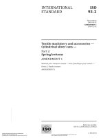
10.2.2 Specimen holder and heat screen (see Figure 2).
10.2.3 Non-fibrous filter paper.
10.2.4 Hand lens, with ×6 magnification.
10.2.5 Electric hotplate, or other suitable heat source.
10.3 Test specimen
One specimen, measuring 100 mm × 100 mm × the thickness of the sheet under test, is required.
10.4 Procedure
Place approximately 200 ml of water in the flask (10.2.1) and bring it to the boil on the electric hotplate (10.2.5).
Place the heat screen (see 10.2.2) in position around the neck of the flask and place the specimen, decorative
face down, centrally over the mouth of the flask and fix it in position by the wire specimen holder (see Figure 2).
The specimen holder shall be heavy enough to prevent the specimen from curling away from the mouth of the
flask.
12
© ISO 2004 – All rights reserved
ISO 4586-2:2004(E)
Key
1
2
specimen
wire specimen holder
3
4
heat screen
aluminium ring
5
Erlenmeyer flask, wide-necked, 250 ml
Figure 2 — Apparatus for resistance to steam (see 10.2)
After the decorative face has been exposed for 1 h to the steam from the boiling water, remove the specimen
and use the non-fibrous filter paper (10.2.3) to remove excess water from the surface of the specimen.
Allow the specimen to recover for 24 h in normal ambient conditions and then examine the central area of the
specimen with the naked eye, corrected if necessary, and under ×6 magnification using the hand lens (10.2.4)
for any change in appearance.
10.5 Test report
The test report shall include the following information:
a) a reference to this part of ISO 4586;
b) the name and type of product;
c) the effect on the surface of the specimen, expressed in accordance with the following rating scale:
Rating 5: No visible change
Rating 4: Slight change of gloss and/or colour, only visible at certain viewing angles
Rating 3: Moderate change of gloss and/or colour
Rating 2: Marked change of gloss and/or colour
Rating 1: Blistering and/or delamination
© ISO 2004 – All rights reserved
13
ISO 4586-2:2004(E)
d) any deviation from the specified procedure;
e) the date of the test.
11 Dimensional stability
11.1 Method A — At elevated temperature
11.1.1 Principle
The test measures the lateral dimensional changes of specimens from the laminate under test over an extreme
range of relative humidities at elevated temperatures.
11.1.2 Apparatus
11.1.2.1 Circulating-air oven, capable of being maintained at (70 ± 2) ◦ C.
11.1.2.2 High-humidity conditioning chamber, with an atmosphere of relative humidity within the range
90 % to 95 % and at a temperature of (40 ± 2) ◦ C.
11.1.2.3 Standard-atmosphere conditioning chamber, with a standard atmosphere of (23 ± 5) ◦ C and
relative humidity (50 ± 5) %.
11.1.2.4 Caliper gauge or other suitable means for measuring length, with a measurement range of at
least 150 mm, graduated to provide a reading accuracy of 0,01 mm. Centering points are recommended but are
not essential.
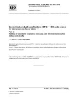
11.1.2.5 Fixture, to maintain specimens from thin laminates in a flat position while measurements are taken.
A suitable fixture is shown in Figure 3.
11.1.2.6 Centre-punch and hammer (optional), suitable for making a small locating indentation in the
surface of the test specimen.
11.1.2.7 Steel rule, graduated in 0,5 mm divisions.
11.1.2.8 Desiccator, of suitable size.
11.1.3 Test specimens
Cut four specimens (120 ± 1) mm square from the sheet under test. The edges shall be smooth and free from
cracks.
Use two specimens for the dry-heat test and two for the high-humidity test.
Before making the first measurements, all specimens shall be kept for at least 72 h in a standard atmosphere of
(23 ± 2) ◦ C and (50 ± 5) % relative humidity.
11.1.4 Procedure
11.1.4.1 General
All measurements of length shall be made to the nearest 0,02 mm. Measurements shall be made within 5 min
after removal of the specimens from the conditioning atmosphere or the desiccator (11.1.2.8).
The specimen shall be kept flat when making length measurements. For thin laminates, a suitable fixture such
as that shown in Figure 3 shall be used.
14
© ISO 2004 – All rights reserved
ISO 4586-2:2004(E)
Dimensions in millimetres
Key
3 mm steel ball and spring
1
2
(3 × 22) mm bolt and nut
3
4
suitable spring to maintain specimen in flat position
3-mm-wide slot
Figure 3 — Fixture to maintain the test specimen in position (see 11.1.2.5 and 11.2.2.5)
With each specimen, use the steel rule (11.1.2.7) to locate the point midway between two adjacent corners and
10 mm in from the corresponding edge. Mark this point, using a centre-punch (11.1.2.6) for instance. Repeat
this for the other three sides of each specimen.
As an alternative to marking the measurement points by punching, they may be scribed or marked on the
surface of the specimen in some other suitable way.
© ISO 2004 – All rights reserved
15
ISO 4586-2:2004(E)
11.1.4.2 Dry-heat test
Taking two specimens, measure the distances between opposite marks (across the centres of the specimens)
to the nearest 0,02 mm in both the machine direction and the transverse direction. Any suitable means
(see11.1.2.4) may be used to measure the distances between the marks. If a centre-punch has been used to
mark the measurement points, measure the distances using a caliper gauge with its points positioned in
opposite locating indentations.
If the machine direction is not known, carry out flexural-strength tests on specimens taken at various angles.
The highest value will usually be given by the specimen cut parallel to the machine direction.
Place both specimens in the oven (11.1.2.1) maintained at (70 ± 2) ◦ C. At the end of 24 h, remove the
specimens and allow them to cool to ambient temperature in the desiccator (11.1.2.8) for 1 h, then remeasure
the distances between the marks.
11.1.4.3 High-humidity test
Taking the remaining two specimens, measure the distances between opposite marks in both the machine
direction and transverse direction. Place both specimens in the high-humidity conditioning chamber (11.1.2.2)
at (40 ± 2) ◦ C and a relative humidity within the range 90 % to 95 %. After (96 ± 4) h, remove each specimen,
wipe it free of surface water with a cloth, and immediately remeasure the distances between the marks.
11.1.5 Expression of results
Calculate the change in measured length as a percentage of the corresponding initial measured length.
Calculate the mean percentage change in machine-direction length and transverse-direction length for each of
the two sets of specimens (i.e. the dry-heat and high-humidity sets) to the nearest 0,05 %.
Calculate the cumulative dimensional change for each direction of the sheet. This change is the sum of the
mean absolute percentage changes in each of the dry-heat and high-humidity tests if the changes are in
opposite directions. If the changes are in the same direction, the larger of the two average changes shall be
taken as the cumulative dimensional change. The absolute figure shall be reported.
An example of results (using measurements in the transverse direction) is shown in Table 1.
The movements in the two tests are in opposite directions, therefore the cumulative dimensional change in the
transverse direction is equal to 0,40 % + 0,65 % = 1,05 %.
Table 1 — An example of dimensional stability at elevated temperature
Dry-heat test
Specimen 1
Specimen 2
Initial distance (mm)
100,28
99,89
Final distance (mm)
99,83
99,52
Change (mm)
Change (%)
− 0,45
− 0,45
Mean
− 0,37
− 0,37
− 0,41
− 0,41 rounded to the nearest 0,05 = − 0,40 %
High-humidity test
Specimen 1
Specimen 2
Mean
Initial distance (mm)
100,11
99,74
Final distance (mm)
100,63
100,49
Change (mm)
+ 0,52
+ 0,52
+ 0,75
+ 0,75
+ 0,64
+ 0,64 rounded to the nearest 0,05 = + 0,65 %
Change (%)
16
© ISO 2004 – All rights reserved
ISO 4586-2:2004(E)
11.1.6 Test report
The test report shall include the following information:
a) a reference to this part of ISO 4586;
b) the name, type and nominal thickness of the product;
c) the cumulative dimensional change for the machine direction;
d) the cumulative dimensional change for the transverse direction;
e) any deviation from the method specified;
f)
the date of the test.
11.2 Method B — At ambient temperature
11.2.1 Principle
The test measures the lateral dimensional changes of specimens from the laminate under test over an extreme
range of relative humidities at ambient temperature.
11.2.2 Apparatus
11.2.2.1 High-humidity conditioning chamber, with an atmosphere of relative humidity (90 ± 3) % and a
temperature of (23 ± 2) ◦ C.
11.2.2.2 Low-humidity conditioning chamber, with an atmosphere of relative humidity (15 ± 5) % and a
temperature of (23 ± 2) ◦ C.
NOTE The low-humidity chamber may be set up to operate either mechanically or chemically to control the temperature at
(23 ± 2) ◦ C and to maintain (15 ± 5) % relative humidity. One way of maintaining the relative humidity at this level is by
using a saturated solution of lithium chloride (LiCl·H2O) placed in a tray within the chamber.
11.2.2.3 Standard-atmosphere conditioning chamber, with an atmosphere of relative humidity (50 ± 5) %
and a temperature of (23 ± 2) ◦ C.
11.2.2.4 Caliper gauge or other suitable means for measuring length, with a measurement range of at
least 150 mm, graduated to provide a reading accuracy of 0,01 mm. Centering points are recommended but are
not essential.
11.2.2.5 Fixture, to maintain specimens from thin laminates in a flat position while measurements are taken.
A suitable fixture is shown in Figure 3.
11.2.2.6 Centre-punch and hammer (optional), suitable for making a small locating indentation in the
surface of the test specimen.
11.2.2.7 Steel rule, graduated in 0,5 mm divisions.
11.2.3 Test specimens
Cut two specimens (120 ± 1) mm square from the sheet under test. The edges shall be smooth and free from
cracks.
Before making the first measurements, the specimens shall be kept for at least 72 h in a standard atmosphere
of (23 ± 2) ◦ C and (50 ± 5) % relative humidity.
© ISO 2004 – All rights reserved
17
ISO 4586-2:2004(E)
11.2.4 Procedure
All measurements of length shall be made to the nearest 0,02 mm. Measurements shall be made within 5 min
after removal of the specimens from the conditioning atmosphere.
The specimen shall be kept flat when making length measurements. For thin laminates, a suitable fixture such
as that shown in Figure 3 shall be used.
With each specimen, use the steel rule (11.2.2.7) to locate the point midway between two adjacent corners and
10 mm in from the corresponding edge. Mark this point, using a centre-punch (11.2.2.6) for instance. Repeat
this for the other three sides of each specimen.
As an alternative to marking the measurement points by punching, they may be scribed or marked on the
surface of the specimen in some other suitable way.
Place both specimens in the high-humidity chamber (11.2.2.1), positioned so that air can circulate freely around
them.
After (96 ± 4) h, remove both specimens from the chamber and immediately measure the distances between
opposite marks (across the centres of the specimens) to the nearest 0,02 mm in both the machine direction and
the transverse direction. Any suitable means (see 11.2.2.4) may be used to measure the distances between the
marks. If a centre-punch has been used to mark the measurement points, measure the distances using a
caliper gauge with its points positioned in opposite locating indentations. Record these measurements as the
initial measurements.
If the machine direction is not known, carry out flexural-strength tests on specimens taken at various angles.
The highest value will usually be given by the specimen cut parallel to the machine direction.
Place both specimens in the low-humidity chamber (11.2.2.2), positioned so that air can circulate freely around
them.
After (96 ± 4) h, remove both specimens from the chamber and immediately remeasure the distances between
the marks. Record these measurements as the final measurements.
11.2.5 Expression of results
For each direction, calculate the average initial length and the average final length.
Calculate the gross dimensional change in each direction, which is the difference between the average initial
and average final measurements expressed as a percentage of the corresponding average initial measured
length, to the nearest 0,05 %.
An example of results (using measurements in the transverse direction) is given below:
Average of two initial measurements = 104,02 mm
Average of two final measurements = 103,05 mm
Gross dimensional change = 0,97 mm
Percentage gross dimensional change, to the nearest 0,05 % = 0,95 %
11.2.6 Test report
The test report shall include the following information:
a) a reference to this part of ISO 4586;
b) the name, type and nominal thickness of the product;
c) the percentage gross dimensional change in the machine direction;
d) the percentage gross dimensional change in the transverse direction;
18
© ISO 2004 – All rights reserved
ISO 4586-2:2004(E)
e) any deviation from the method specified;
f)
the date of the test.
12 Resistance to impact by small-diameter ball
12.1 Principle
A specimen from the sheet under test is bonded to wood chipboard to simulate service conditions and its
decorative surface is subjected to the impact of a 5 mm steel ball mounted at one end of a spring-loaded bolt.
The minimum spring force needed to cause visible damage is used as a measure of resistance to impact.
12.2 Materials
12.2.1 High-quality fine-faced wood chipboard, 18 mm to 20 mm nominal thickness with a tolerance of
± 0,3 mm, density 625 kg/m3 to 700 kg/m3 and moisture content (9 ± 2) %.
Where the specimen is bonded to chipboard, the test actually measures the impact resistance of the whole
composite material, i.e. laminate, adhesive and substrate. The correct choice of chipboard quality is therefore
very important in achieving good reproducibility with this test. In cases of dispute, the same test shall be carried
out on chipboards from three different suppliers.
12.2.2 Urea-formaldehyde adhesive, containing approximately 15 % filler, or an equivalent adhesive.
12.2.3 Solution of dye in alcohol, graphite or talcum, to contrast with the colour of the sheet under test
(optional).
12.3 Apparatus
12.3.1 Impact tester (see Figure 4), consisting of an impact bolt with a 5 mm steel ball mounted at one end,
which is projected once against the surface under test by the release of a compression spring. The spring
compression force before release can be adjusted continuously from 0 N to 90 N by means of a force-setting
barrel (housing).
The newton metre (N · m) scale also provided on the tester is only to be used for orientation, as the introduction
of a non-linear scale involves relatively great inaccuracies.
The compression spring is 100 mm long when released and has a constant of 1 962 N/m ± 50 N/m. It is
compressed by drawing back the impact bolt and is held in the loaded position by a retainer which engages in
the bolt. It is released to deliver the impact blow by a release unit which withdraws the retainer.
12.3.2 Force-producing arrangement (for example a scale-pan and weights), capable of being suspended
from the impact bolt to exert a compressive force on the spring.
12.3.3 Support fixture (see Figure 5), which clamps to the shaft of the impact tester and provides a
convenient mounting of sufficient mass for the tester to be held at right angles to the surface of the specimen
and to avoid recoil following the release of the impact bolt.
12.3.4 Steel plate, having dimensions of approximately 300 mm × 300 mm × 50 mm.
12.3.5 Hand lens, with approximately ì6 magnification (optional).
â ISO 2004 – All rights reserved
19
ISO 4586-2:2004(E)
Dimensions in millimetres
Key
1
impact bolt
2
3
retainer
release lever
4
5
knob
force-setting
barrel (housing)
compression
spring
steel ball
6
7
Figure 4 — Impact tester (shown with spring compressed) (see 12.3.1)
Dimensions in millimetres
Key
1
2
observation slot
shaft of impact tester
3
4
clamp screw
pressure bolt
5
6
steel ball
foot
Figure 5 — Support fixture for impact tester (see 12.3.3)
20
© ISO 2004 – All rights reserved
ISO 4586-2:2004(E)
12.4 Test specimens
Specimens shall be prepared by uniformly bonding a piece of the sheet under test to the wood chipboard
(12.2.1), using the specified adhesive (12.2.2). About ten specimens, each 230 mm ± 5 mm square, shall be
prepared. The bonded specimens shall be preconditioned for at least 7 days at 23 ◦ C ± 2 ◦ C and (50 ± 5) %
relative humidity before being used for the test.
12.5 Calibration of the impact tester
Suspend the tester (12.3.1) with the impact bolt pointing upwards so that its longitudinal axis is free to hang
vertically under gravity.
Set the force-setting barrel, which serves to vary the impact force, to zero on the scale. Compress the spring by
a force Fe (calibration force) using a suitable arrangement (for example weights in a scale-pan) (12.3.2)
suspended from the knob used to draw back the impact bolt, ensuring that the bolt is clear of the retainer of the
release unit.
Turn the force-setting barrel until the retainer of the release unit is just in contact with the impact bolt. This
position can be determined by increasing or decreasing the compressing force very slightly to observe whether
the retainer is just in contact. Record the indicated force Fx on the scale of the instrument corresponding to the
calibration force Fe .
Repeat this calibration procedure for various values of Fx in the range required, and draw a graph relating
values of the scale reading Fx to values of the calibration force Fe (see Figure 6 for an example).
The graph will be an approximately straight line which will not pass through the origin, because a constant but
undetermined force is exerted during the calibration procedure by the mass of the impact bolt and any
suspension arrangement (for example, a scale-pan). Draw a second line passing through the origin and parallel
to the first line. This second line is the calibration graph of the instrument and shall be used to correct every
indicated force Fx employed in testing.
Prepare a new calibration graph after every 500 tests.
Key
X
calibration force Fe (N)
Y
scale reading on instrument (N)
Figure 6 — Example of calibration graph relating actual force to scale value (see 12.5)
© ISO 2004 – All rights reserved
21