control of current saturation and threshold voltage shift in indium oxide nanowire transistors with femtosecond laser annealing
Bạn đang xem bản rút gọn của tài liệu. Xem và tải ngay bản đầy đủ của tài liệu tại đây (915.07 KB, 7 trang )
LEE ET AL. VOL. 5
’
NO. 2
’
1095– 1101
’
2011 1095
www.acsnano.org
January 11, 2011
C 2011 American Chemical Society
Control of Current Saturation and
Threshold Voltage Shift in Indium
Oxide Nanowire Transistors with
Femtosecond Laser Annealing
Chunghun Lee,
†
Pornsak Srisungsitthisunti,
†
Sangphill Park,
†
Seongmin Kim,
†
Xianfan Xu,
†
Kaushik Roy,
†
David B. Janes,
†
Chongwu Zhou,
‡
Sanghyun Ju,*
,
§
and Minghao Qi*
,
†
†
School of Electrical and Computer Engineering, and Birck Nanotechnology Center, Purdue University, 465 Northwestern Avenue, West Lafayette, Indiana 47907,
United States ,
‡
Department of Electrical Engineering, University of Southern California, 3710 McClintock Avenue, Los Angeles, California 90089, United States , and
§
Department of Physics, Kyonggi University, Suwon, Gyeonggi-Do 443-760, Republic of Korea
F
lexible and/or transparent electronics
have attracted significant interest due
to their potential applications includ-
ing see-through, lightweight, and conform-
able products.
1-5
In particular, nanowire
transistors (NWTs) may be better suited for
future display products requiring trans-
parent electronic switches because NWTs offer
higher carrier mobility than those of thin-
film transistors (TFTs), as well as the low-
temperature processes that are compatible
with optical transparency requirements.
2-6
High-performance NWTs typically use ZnO,
SnO
2
,andIn
2
O
3
semiconducting oxide nano-
wires, or aligned/random networked single-
walled carbon nanotubes.
1,2,4,6,7
Many reports
have suggested that NWTs have higher
performance and more stable transistor
characteristics compared with amorphous
silicon and polysilicon TFTs, especially on
field effect mobility (μ
eff
) and subthreshold
slope (SS).
8-11
Despite these excellent prop-
erties (high performance, high sensitivity,
and high efficiency), however, there are still
many issues to be resolved before NWTs can
find practical digital and analogue applica-
tions. One issue is to place nanowires at the
desired places of the wafer/board to form
designed patterns. To manufacture inte-
grated nanowire-circuits, it would be crucial
to develop the technology to control the
amount and shape of the nanowire in the
course of its arrangement as well as to
enhance the characteristics of nanowire
elements. Another issue is to achieve highly
saturated transistor current and robust semi-
conductor characteristics, such as uniform
and controllable threshold voltages (V
th
)
and SS. Even though many unpassivated
NWTs have been demonstrated, source-
drain currents are not saturated but rather
increase slightly line arly i n most reports.
2,4,7-12
Little research, to our knowledge, has been
conducted to reduce such linear increase
even though it is perhaps the biggest ob-
stacle for the incorporation of NWTs in such
transparent circuitry on low-temperature
substrates, as current saturation is the key
benefit of transistors. While high-tempera-
ture annealing or doping could be used to
mitigate this problem in commercial thin-
film transistors, elevated temperatures can
change the properties of semiconducting
nanowires, and there are difficulties in ad-
justing the doping level uniformly. Further-
more, these methods are in most cases
incompatible with flexible device panels.
*Address correspondence to
,
Received for review October 12, 2010
and accepted December 23, 2010.
Published online
10.1021/nn102723w
ABSTRACT Transistors based on various types of nonsilicon nanowires have shown great
potential for a variety of applications, especially for those that require transparency and low-
temperature substrates. However, critical requirements for circuit functionality, such as saturated
source-drain current and matched threshold voltages of individual nanowire transistors in a way that
is compatible with low temperature substrates, have not been achieved. Here we show that
femtosecond laser pulses can anneal individual transistors based on In
2
O
3
nanowires, improve the
saturation of the source-drain current, and permanently shift the threshold voltage to the positive
direction. We applied this technique and successfully shifted the switching threshold voltages of
NMOS-based inverters and improved their noise margin, in both depletion and enhancement modes.
Our demonstration provides a method to trim the parameters of individual nanowire transistors, and
suggests potential for large-scale integration of nanowire-based circuit blocks and systems.
KEYWORDS: threshold voltage shift
•
In
2
O
3
•
nanowires
•
femtosecond laser
•
annealing
•
transistors
ARTICLE
LEE ET AL. VOL. 5
’
NO. 2
’
1095– 1101
’
2011 1096
www.acsnano.org
Here we report the effects of femtosecond laser
annealing on fully transparent inverters consisting of
two In
2
O
3
NWTs, and show that their current saturation
is improved (3- 7 times increase in output resistance),
and that the inverting voltages can be permanently
shifted. Focused laser annealing is useful in that it can
be applied selectively to small areas that require high
temperatures. As a result, component damages during
conventional thermal annealing of the entire panel can
be avoided and unwanted effects in those areas could
be excluded from the annealing process.
13,14
In our
process, we focused the laser beam spot at the contact
area rather than on the nanowires themselves to
avoid damaging or sputtering them away (Figure 1a).
Furthermore, this annealing process could be possible
even on plastic panels because instantaneous laser
annealing, which is performed on a length scale of
several micrometers, does not affect the temperature
of the entire panel. Using this method, we demon-
strated switching threshold voltage control in fully
transparent NMOS inverters with the load being a
diode connected n-type In
2
O
3
NW transistor operated
in both the enhanced mode and depletion mode.
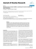
Figure 1a is a cross-sectional view of the fully
transparent NWT with the bottom gate structure, con-
sisting of transparent glass substrate (corning glass),
abuffer layer of 100 nm thick silicon dioxide, a
gate electrode made from 110 nm thick patterned
indium-tin oxide (ITO), a 20 nm thick Al
2
O
3
gate
insulator through atomic layer deposition (ALD), a
single-crystal semiconducting In
2
O
3
nanowire as the
active channel, and 110 nm thick ITO for source/drain
(S/D) electrodes. In
2
O
3
nanowires were synthesized
through a laser ablation method (band gap E
g
≈
3.6 eV, and diameter D ≈ 20 nm).
15
They are trans-
parent to visible light, and are suitable for transparent
and flexible TFTs. Meanwhile, ITO is a promising candi-
date as transparent conductors for gate, source, and
drain electrodes
16-18
in TFTs. High-κ Al
2
O
3
gate di-
electric showed excellent insulating properties, with an
electrical breakdown field of >8 MV/cm and a dielectric
constant of ∼9.
19
Figure 1b shows the field emission
scanning electron microscope (FE-SEM) image of seve-
ral NWT devices including all transparent components.
The lengths of single In
2
O
3
nanowire (∼20 nm dia-
meter) addressed between S/D electrodes were ∼3 μm
to avoid the complications of the short channel effects.
Figure 1a also illustrates the femtosecond laser anneal-
ing process. The unique aspect of our annealing pro-
cess was that laser pulses were only focused on and
scanned along the S/D contact regions using its parti-
cular property of localized energy input (beam spot
diameter ∼1.22 μm). The pulse wavelengths were
centered at 800 nm, which has energy below the band
gap of In
2
O
3
. Therefore we expected the effect to be
likely different from the annealing using excimer
lasers,
13
which has a photon energy above the band
gap of the nanowire.
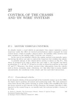
The most prominent effects of laser annealing were
the improvement of the current saturation and the
positive shift of the threshold voltage V
th
. Figure 2a
shows the drain current versus drain-to-source voltage
(I
ds
-V
ds
) characteristics for a representative NWT with
V
gs
ranges from -1.5 to 4 V in 0.5 V steps before (black
open square) and after (red open circle) laser annealing
at 0.43 J/cm
2
/pulse. The I
ds
-V
ds
curves of as-fabricated
devices deviated significantly from the expected res-
ponse of a long-channel transistor even when V
ds
values were in the saturation region (V
ds
> V
gs
- V
th
),
and exhibited significant drain conductance or low
output resistance (r
o
). The annealed devices, on the
other hand, appeared to have induced V
th
shifts to the
positive direction, which resulted in smaller saturation
current at the same gate voltage. However, the drain
currents showed significantly higher output resistance.
We first identify the threshold voltages before and
after the femtosecond laser annealing. The linear-scale
drain current versus gate-source voltage (I
ds
-V
gs
)of
the fully transparent single In
2
O
3
NWT at V
ds
= 0.1, 0.5,
and V
ds
= 4.0 V before (square) and after (circle) laser
annealing is shown in Figure 2b. The V
th
can be
extrapolated from the slop of the drain current increase
and the values were around -2.9 V at V
ds
= 0.1 V and
around -2.7 V at V
ds
= 0.5 V for as-fabricated devices.
However, the V
th
values shifted along positive direction
Figure 1. Schematic and scanning-electron micrograph of
an In
2
O
3
-based NWT. (a) The cross-sectional schematic of a
fully transparent, bottom gated nanowire transistor. The
femtosecond laser pulses focus on the ITO source and drain
area and scans along the edge of the source and drain pads.
Laser pulses do not scan across the channel of the transistor,
or the exposed portion of the nanowire. (b) Top-view
scanning-electron micrograph of a fully transparent NWT.
ITO was used for gate, source, and drain. The inset shows a
single In
2
O
3
nanowire (D/L ≈ 20 nm/3 μm) addressed
between source and drain.
ARTICLE
LEE ET AL. VOL. 5
’
NO. 2
’
1095– 1101
’
2011 1097
www.acsnano.org
to V
th
≈ 0.2 and 0.5 V, respectively, after the laser
annealing. Data from other V
ds
values showed similar
results and we estimate the threshold voltage to be
around -2.8 V for as-fabricated NWT and around 0.4 V
for annealed NWT. The apparent reduction in source-
drain current after the laser annealing can thus be
explained by the positive shift of the threshold voltage.
To compare the output resistance, we plotted
the I
ds
-V
ds
characteristics at V
gs
= -2.5 V for the
as-fabricated device, and at V
gs
= 1 V for the annealed
device (Figure 2c). The saturation currents were similar,
as the V
gs
- V
th
were similar (0.3 V for as-fabricated and
0.6 V for annealed NWT). For V
ds
> 1.5 V, which is
appreciably higher than V
gs
- V
th
, the device should
be in saturation state. However, the as-fabricated
device clearly showed a weak saturation, or small
output resistance, while the annealed device showed
strong saturation. We applied linear regression to
calculate the output resistance of the transistor using
I
ds
-V
ds
data in the range of 1.5 V < V
ds
< 5 V. The output
resistance for the as-fabricated transistor was 37 MΩ,
while for the annealed sample it was 200 MΩ, showing
a 5.4-fold increase. Similar increase of output resistance
(3-7-fold) was observed at other saturation current
values. Strong saturation is very important for almost
all circuit applications requiring transistors and we
believe our method is the first to achieve such a goal
with extremely low thermal budget, and without
surface modification. Temporary V
th
shifts have been
reported for In
2
O
3
NWTs after UV light exposure.
20
However, such exposure shifts the threshold to the
negative direction and the device returns to its pre-
vious operation state shortly. The effect of femto-
second laser annealing appears to be permanent,
and is stable in air. When we remeasured nanowire
transistors after a few days and after several weeks,
we observed negligible variations.
This permanent change of V
th
suggests that the
postmetallization S/D annealing with a femtosecond
laser could also be a tuning method to adjust the V
th
values of individual nanowires. To illustrate this poten-
tial, two different values of annealing power were
sequentially applied to the same nanowire transistor
and we o bserved a positive V
th
shift after each annealing.
We first measured the I
ds
-V
gs
(V
ds
= 0.5 V) of another
representative NWT before laser annealing, and found
the V
th
to be -1 V, and then applied femtosecond laser
annealing at 0.14 J/cm
2
/pulse. A V
th
shift to the positive
direction by 0.5 V was observed. We then performed a
second annealing on the same device, with the energy
of 0.43 J/cm
2
/pulse. A further shift toward the positive
direction by 2.25 V was shown in Figure 2d. The
additional power (in our case 0.43 J/cm
2
/pulse) was
essential because when we tried to apply the same
annealing power, a negligible V
th
shift was observed.
Figure 2d shows the log-scale I
ds
-V
gs
characteristics of
Figure 2. Effect of femtosecond laser annealing on the output resistance and threshold voltage of a NWT. (a) The I
ds
-V
ds
characteristic of a fully transparent In
2
O
3
NWT. V
gs
ranges from -1.5 to 4 V in 0.5 V steps before (black open square) and after
(red open circle) laser annealing. (b) V
th
shift of the NWT before and after laser annealing at drain-to-source voltages of
V
ds
= 0.1, 0.5, and 4.0 V. (c) The I
ds
-V
ds
characteristic for V
gs
= -2.5 V before the laser annealing (blue curve) and for V
gs
=1V
after the laser annealing (red curve). The saturation currents are similar, yet the output resistance significantly increased
after laser annealing. (d) The log-scale I
ds
-V
ds
characteristic of an In
2
O
3
NWT at V
ds
= 0.5 V with different power conditions:
before applying femtosecond laser annealing (black open square), after 0.14 J/cm
2
/pulse femtosecond laser annealing
(red open circle), and after an additional 0.43 J/cm
2
/pulse femtosecond laser annealing (blue open diamond), respectively.
ARTICLE
LEE ET AL. VOL. 5
’
NO. 2
’
1095– 1101
’
2011 1098
www.acsnano.org
an In
2
O
3
NWT at V
ds
= 0.5 V for different annealing
conditions: before applying femtosecond laser (black
open square, V
th
= -1V,I
on
/I
off
≈ 1.19 Â 10
4
,SS=
2.2 V/dec, and μ
eff
= 1.12 Â 10
2
cm
2
/V
3
s); after femto-
second laser annealing at pulse energy of 0.14 J/cm
2
/
pulse (red open circle, V
th
= -0.5 V, I
on
/I
off
≈ 1.76 Â 10
4
,
SS = 2.2 V/dec, μ
eff
= 1.47 Â 10
2
cm
2
/V
3
s); and after an
additional femtosecond laser annealing at 0.43 J/cm
2
/
pulse (blue open diamond, V
th
= 1.75 V, I
on
/I
off
≈ 2.23 Â
10
4
, SS = 2.2 V/dec, μ
eff
= 1.77 Â 10
2
cm
2
/V
3
s),
respectively. After each femtosecond laser annealing,
the I
on
/I
off
and μ
eff
both improved slightly. In all calcu-
lations, the field-effect mobility [μ =dI
ds
/dV
gs
 L
2
/C
i
Â
1/V
ds
] was calculated by using the cylinder-on-plate
(COP) capacitance model [C
i
=2πε
0
k
eff
L/cosh
-1
(1 þ
t
ox
/r)]. Therefore, femtosecond laser annealing appar-
ently has not only improved current saturation (by
increasing output resistance by 3-7-fold) but also
adjusted threshold voltages of individual In
2
O
3
nano-
wire transistors. Such effects might provide a solution
to one of the long lasting problems in large scale
integration of devices made from NWTs: individual
trimming of NWT characteristics to match the require-
ments of functional devices, such as inverters, current
mirrors, and amplifiers.
As an application for our capability of adjusting the
V
th
values of individual NWTs, we fabricated a fully
transparent inverter with both transistors made from
In
2
O
3
nanowires. An inverter is one of the fundamental
building blocks of logic circuits, and its switching
threshold (or trip) voltage is preferred to be located
at the middle of the supply voltage, which requires the
proper positioning of the V
th
values of both transistors.
Moreover, high and early saturation of the transistors
are also desirable to improve the noise margin by
maintaining the gain in the transition region. Femto-
second laser annealing introduced here appears to be
an ideal method to improve the inverter characteris-
tics. Figure 3a shows the two types of inverters we have
fabricated, one with depletion mode load (left) and the
other with enhanced mode load (right). The two types
of inverters are the possible candidates when there is
no complementary component such as p-type nano-
wire MOS in the pull-up path. SEM images of depletion
mode inverter with the pull-up and pull-down paths
are shown in Figure 3b. Both topologies worked suc-
cessfully with a supply voltage of 4 V throughout the
experiments. Femtosecond laser annealing was selec-
tively applied to individual transistors to improve the
voltage transfer characteristic (VTC) of inverters, speci-
fically the noise margins, which are defined as follows:
NM
H
= V
DD
- V
IH
, NM
L
= V
IL
, where V
IL
and V
IH
are input
voltages at th e operational points where dV
OUT
/dV
IN
= -1.
NM
L
and NM
H
represent noise immunity on input
logic values: “0” and “1”, respectively. Thus, a balance
between NM
L
and NM
H
is required to maximize noise
immunity on both logic inputs, and the gain by the
inverter in the transition region has to be maintained
high to preserve the total noise margin (NM
L
þ NM
H
).
As shown in Figure 3c, the laser annealing maintained
transconductance (changes were insignificant) of NWT
while it shifted V
th
. This allowed us to control the
switching threshold voltage of an inverter with the
same gain at the switching threshold voltage (V
M
), or
trip voltage, which will maximize the noise margin of
the inverter. The inset of Figure 3c shows that the
hysteresis
21
was relatively reduced after the femto-
second laser annealing. In the case of the depletion
mode inverter, the diode connected NMOS (M
1
)is
always ON as M
1
has a negative V
th1
and its V
gs1
is
fixed at 0, see Figure 3a. When the input is low (“0”) and
transistor M
2
is off, M
1
keeps driving the output high
until V
ds
of M
1
drops to zero, which means that V
OUT
is
the same as the supply voltage. When the input state
changes to high (“1”), M
2
starts to discharge output
quickly. This can be explained by the relative magni-
tudes of V
gs
- V
th
for M
2
and for M
1
, V
gs1
- V
th1
= -V
th1
,
since V
gs1
for M
1
is always 0. When V
gs2
- V
th2
= V
IN
-
V
th2
for M
2
is larger than -V
th1
of M
1
, the current is
limited by M
1
; and V
ds2
of M
2
quickly reduces to near
zero to match the small current set by M
1
. This ensures
a fast switching from high to low. Therefore the trip
voltage is mostly determined by the V
th
of M
2
and r
o
of
M
1
and M
2
, and could be smaller (1.5 V) than half of the
supply voltage, 2 V, as shown in Figure 3d. To achieve
enhanced noise margin, the trip voltage is preferred to
be shifted to close to 2 V. NM
H
was around 1.8 V, NM
L
was 0.8 V, and trip voltage was 1.5 V before femto-
second laser annealing, which was smaller than half of
the supply voltage and therefore reduced the low
voltage input noise immunity. However, through femto-
second laser annealing, trip voltage was changed to
2.2 V, NM
H
to around 1 V, and NM
L
to around 1.5 V,
which achieved a better balance between NM
H
and
NM
L
. Moreover, the function of M
1
should remain
complementary to that of M
2
, so the threshold voltage
of M
1
had to be maintained negative while that of M
2
is
shifted along the positive direction. This requires
local tuning of the pull-down transistor (M
2
) without
significantly affecting the pull-up transistor ( M
1
). Our
femtosecond laser annealing meets those require-
ments and can be applied selectively to the pull-down
transistor to shift the switching voltage of inverter to
be in the middle of the supply rail. The voltage transfer
characteristics in Figure 3d show that enhanced noise
margin was achieved by shifting the trip point of
inverter from 1.5 to 2.2 V. Moreover, the hysteresis of
the inverter device was modest over the bias region
before and after administering the annealing. Thus, it
might be possible to use this technique to control the
switching threshold voltage of an inverter, which is
important to achieve a high noise margin for many
circuit applications.
ARTICLE
LEE ET AL. VOL. 5
’
NO. 2
’
1095– 1101
’
2011 1099
www.acsnano.org
The operating principle of enhancement mode load
transistor is different compared to depletion mode
load inverter. Figure 3e shows that output voltage
was not completely zero even when the input was
driven high. Also the transition from high to low was
not as sharp as that of the depletion mode. These were
primarily due to the static current through M
3
and M
4
when M
4
was turned on. Unlike the depletion mode,
the V
gs3
- V
th3
increases when V
OUT
drops, which
increases the static current. At this time, the output
voltage was determined by the on resistance (R
ON
)
values of M
3
and M
4
as Ohm's law is applicable. Thus,
the ratio of pull-up and pull-down transistor was
important in this case. In practice, this ratio can be
achieved by adjusting the channel length. In addition,
high R
ON
of M
3
was required to obtain a sharper
transfer from high to low state. The starting of transi-
tion from high to low is at a small negative voltage, as
V
th
of M
4
exists in the slightly negative area. Therefore,
the value of NM
L
was around 0.3 V before administer-
ing femtosecond laser annealing, which is a com-
promised operation. The femtosecond laser annealing
produced a selective positive shift of V
th
for M
4
.Asa
result, the value of NM
L
increased to around 1.2 V.
Meanwhile, NM
H
decreased from around 0.9 to 0.3 V,
due to the positive threshold voltage shift. However,
the total noise margin, NM
L
þ NM
H
, increased from
1.2 to 1.5 V. Therefore, femtosecond laser annealing
improved noise immunity by increasing the total noise
margin, NM
H
þ NM
L
. Figure 3e shows the effect of
femtosecond laser annealing on an enhancement
mode inverter: the trip voltage was shifted to the
positive direction toward half of the supply voltage,
and the total noise margin was improved. The hyster-
esis of this inverter was more prominent than that of
the depletion mode, and we are investigating the
causes and ways to mitigate them.
Finally, our inverter is highly transparent. Figure 4
shows the optical transmission spectra through the
fully transparent NMOS inverters using In
2
O
3
nano-
wires on a glass substrate in the 350-1250 nm wave-
length range. The optical transmission value was
∼82%. Note that the optical transmission value of
corning glass substrate is ∼92%. The NWT array re-
gions were 1.0 Â 0.5 in. (the glass substrate was 1.5 Â
1.0 in.) and contained ∼1500 NWT device patterns;
and the entire substrate was coated with the Al
2
O
3
gate insulator. The source/drain regions and the gate
Figure 3. Shifting the switching threshold voltage of an inverter consisting of two NMOS NWTs. (a) Schematic for the circuit of
depletion (left) and enhancement (right) mode inverters. (b) SEM images of depletion mode inverters with pull-up and pull-
down path. (c) The drain current versus gate-source voltage (I
ds
-V
gs
) of the fully transparent single In
2
O
3
NWT at V
d
= 0.5 V.
The threshold voltage (V
th
), on-off current ratio (I
on
/I
off
), field effect mobilities (μ
eff
), and subthreshold slope (SS) of NWTs
before laser annealing were -0.25 V, ∼3 Â 10
4
, 83.6 cm
2
V
-1
s
-1
, and ∼0.9 V/dec, respectively. After laser annealing with a
fluence of 0.43 J/cm
2
/pulse, those values were changed to 0.6 V, ∼3.2 Â 10
4
, 78.6 cm
2
V
-1
s
-1
, and ∼0.9 V/dec, respectively.
The inset details the hysteresis effect, which can be clearly seen before the laser annealing (black curves), but reduced after
the laser annealing (red curves). (d) Voltage transfer curves of the inverter before (black squares) and after (red squares) the
laser annealing for the depletion mode load. (e) Voltage transfer curves before(black squares) and after (red squares)the laser
annealing for the enhanced mode load.
ARTICLE
LEE ET AL. VOL. 5
’
NO. 2
’
1095– 1101
’
2011 1100
www.acsnano.org
regions covered ∼40% and ∼60% of the total NWT
array region, respectively. Since In
2
O
3
nanowires do
not cover much of the e ntire NWT array and the
diameter of the NWs was only 20 nm, their optical
absorption was negligible. The inset in Figure 4 shows
the substrate with fully transparent NMOS inverters
over an opaque layer. The texture on the paper is
clearly seen through the device substrate.
In conclusion, it is important to improve the perfor-
mance of as-fabricated nanowire devices as they typi-
cally suffer from weak saturation and unpredictable
threshold voltages. The thermal budget of annealing is
typically limited by the low-temperature requirements
of transparent and flexible substrates. Femtosecond
lasers could be focused onto and tune individual NWTs.
However, they can also damage the NWTs easily. The
direct illumination of nanowires was avoided in our
annealing process so that damaging of NWTs did not
occur. This was evidenced by the preservation and
slight improvement of other major performance para-
meters, such as mobility, on-off current ratio, and sub-
threshold slope. The improvement of current saturation,
on the other hand, is desirable in most applications.
Since our femtosecond laser photons have energy
below the band gap of In
2
O
3
nanowires, femtosecond
laser annealing is expected to be mainly thermal,
possibly forming an improved single-crystalline In
2
O
3
nanowire structure. The short pulse duration may
result in ITO photophysical bond breaking instead of
classical melting,
22
consequently forming ITO spikes
into the nanowire channel to improve the contact-
channel interface, modifying the Schottky barrier
height and the effective doping in the nearby semi-
conductor region. Further investigation of the mechan-
ism behind such annealing effects is interesting and
ongoing. This study provides insights into the contact-
dominated transistor properties, in terms of the effects
on output resistance and V
th
.
Combined with the excimer laser annealing,
13
which
shifts the threshold voltage to the negative direction
by increasing the number of oxygen vacancies, one
could envision full trimming capability of the threshold
voltages of NWTs and maintaining high current satura-
tion, thus opening the possibility of constructing
sophisticated circuit blocks or other functional devices
made from NWTs, and significantly advance our knowl-
edge on flexible, and transparent electronics on low-
temperature substrates. Controlling the threshold vol-
tages of nanowires is of central importance to any
practical integrated circuits. The semiconductor indus-
try enjoys highly uniform doping and high-precision
manufacturing (i.e., critical dimension control) to
achieve uniform threshold voltages. While manu-
facturing of non-Si nanowire based transistors will
certainly improve with novel techniques, it is unlikely
that they will match the level of control in CMOS
technologies, therefore the femtosecond laser tuning
of individual NWT presented here would be very
important in manufacturing NWTs if large circuit blocks
are to function as designed. We note that there could
be other ways to alter the transistor characteristics,
such as surface passivation and chemical modifica-
tions. Femtosecond laser annealing appears to be
noninvasive, and still preserves the flexibility of apply-
ing the above-mentioned tuning process. Thus it would
be a useful trimming method for future NWT-based
integrated circuit manufacturing.
METHODS
Famtosecond Laser Anneal and I-V Measurement. The laser an-
nealing source was a Ti:Sapphire laser operating at 800 nm. The
laser pulse duration was 50 fs and the repetition rate was 1 kHz.
Laser transmitted power varied from 1.67 μW (average energy
fluence rate of 0.14 J/cm
2
/pulse) to 5 μW (average energy
fluence rate of 0.43 J/cm
2
/pulse). The transmission spectra of
normal incident linearly polarized light were collected with a
Lambda 950 spectrophotometer (Perkin-Elmer). Electrical char-
acterizations was performed with a semiconductor parameter
analyzer (HP 4156A).
Acknowledgment. This research was supported by the
Defense Advanced Research Projects Agency under contract
NIRT-0707817, by the Air Force Office of Scientific Research
under contract FA9550-08-1-0379, and by the National
Research Foundation of Korea (NRF) funded by the Ministry of
Education, Science and Technology (2010K000990, 2010-
0019108, and 2010-0016473).
REFERENCES AND NOTES
1. Wang, L.; Yoon, M H.; Lu, G.; Yang, Y.; Facchetti, A.; Marks,
T. J. High Performance Transparent Inorgani c-Organic
Hybrid Thin-Film N-type Transistors. Nat. Mater. 2006, 5,
893–900.
2. Ju, S.; Facchetti, A.; Xuan, Y.; Liu, J.; Ishikawa, F.; Ye, P.; Zhou,
C.; Marks, T. J.; Janes, D. B. Fabrication of Fully Transparent
Nanowire Transistors for Transparent and Flexible Electron-
ics. Nat. Nanotechnol. 2007, 2, 378–384.
Figure 4. Optical transmission spectrum through the entire
NWT inverter structures. The inset shows the high trans-
parency of the substrate with 1500 NWT inverter devices;
with the texture on the layer below the substrate clearly
visible.
ARTICLE
LEE ET AL. VOL. 5
’
NO. 2
’
1095– 1101
’
2011 1101
www.acsnano.org
3. Ju, S.; Li, J.; Liu, J.; Chen, P C.; Ha, Y G.; Ishikawa, F.; Chang,
H.; Zhou, C.; Facchetti, A.; Janes, D. B.; Marks, T. J.; et al.
Transparent Active Matrix Organic Light-Emitting Diode
Displays Driven by Nanowire Transistor Circuitry. Nano
Lett. 2008, 8, 997–1004.
4. Azulai, D.; Belenkova, T.; Gilon, H.; Barkay, Z.; Markovich,
G. Transparent Metal Nanowire Thin Films Prepared in
Mesostructured Templates. Nano Lett. 2009, 9,4246–4249.
5. Freer, E. M.; Grachev, O.; Duan, X.; Martin, S.; Stumbo, D. P.
High-Yield Self-Limiting Single-Nanowire Assembly with
Dielectrophoresis. Nat. Nanotechnol. 2010, 5, 525–530.
6. Wang, Z. L. Nanobelts and Nanostructures of Transparent
Conducting Oxides. In Nanowires and Nanobelts: Materials,
Properties and Devices; Wang, Z. L., Ed.; Springer: New York,
2006; Vol. 2,pp47-71.
7. Hur, S H.; Park, O. O.; Rogers, J. A. Extreme Bendability of
Single-Walled Carbon Nanotube Networks Transferred
from High-Temperature Growth Substrates to Plastic and
Their Use in Thin-Film Transistors. Appl. Phys. Lett. 2005,
86, 243502.
8. Cha, S. N.; Jang, J. E.; Choi, Y.; Amaratunga, G. A. J.; Ho, G. W.;
Welland, M. E.; Hasko, D. G.; Kang, D J.; Kim, J. M. High
Performance ZnO Nanowire Field Effect Transistor Using
Self-Aligned Nanogap Gate Electrodes. Appl. Phys. Lett.
2006, 89, 263102.
9. Xiang, J.; Lu, W.; Hu, Y.; Wu, Y.; Yan, H.; Lieber, C. M. Ge/Si
Nanowire Heterostructures as High-Performance Field-
Effect Transistors. Nature 2006, 441, 489–493.
10. Cui, Y.; Zhong, Z.; Wang, D.; Wang, W. U.; Lieber, C. M. High
Performance Silicon Nanowire Field Effect Transistors.
Nano Lett. 2003, 3, 149–152.
11. Chang, P C.; Fan, Z.; Chien, C J.; Stichtenoth, D.; Ronning,
C.; Lu, J. G. High-Performance ZnO Nanowire Field Effect
Transistors. Appl. Phys. Lett. 2006, 89, 133113.
12. Wang, D.; Wang, Q.; Javey, A.; Tu, R.; Dai, H.; Kim,
H.; Mclntyre, P. C.; Krishnamohan, T.; Saraswat, K. C.
Germanium Nanowire Field-Effect Transistors with SiO
2
and High- κ HfO
2
Gate Dielectrics. Appl. Phys. Lett. 2003,
83, 2432–2434.
13. Maeng, J.; Heo, S.; Jo, G.; Choe, M.; Kim, S.; Hwang, H.; Lee,
T. The Effect of Excimer Laser Annealing on ZnO Nano-
wires and Their Field Effect Transistors. Nanotechnology
2009, 20, 095203.
14. Misra, N.; Xu, L.; Pan, Y.; Cheung, N.; Grigoropoulos, C. P.
Excimer Laser Annealing of Silicon Nanowires. Appl. Phys.
Lett. 2007, 90, 111111.
15. Liu, Z.; Zhang, D.; Han, S.; Li, C.; Tang, T.; Jin, W.; Liu, X.;
Lei, B.; Zhou, C. Laser Ablation Synthesis and Electron
Transport Studies of Tin Oxide Nanowires. Adv. Mater.
2003, 15, 1754–1757.
16. Fortunato, E.; Pimentel, A.; Goncalves, A.; Marques, A.;
Martins, R. High Mobility Amorphous/Nanocrystalline
Indium Zinc Oxide Deposited at Room Temperature. Thin
Solid Films 2006, 502, 104–107.
17. Yaglioglu, B.; Yeom, H Y.; Paine, D. C. Crystallization of
Amorphous In
2
O
3
-10 wt % ZnO Thin Films Annealed in
Air. Appl. Phys. Lett. 2005, 86, 261908.
18. Minami, T.; Yamamoto, T.; Toda, Y.; Miyata, T. Transparent
Conducting Zinc-Co-Doped ITO Films Prepared by Mag-
netron Sputtering. Thin Solid Films 2000, 373, 189–194.
19. Lin, H. C.; Ye, P. D.; Wilk, G. D. Leakage Current and
Breakdown Electric-Field Studies on Ultrathin Atomic-
Layer-Deposited Al
2
O
3
on GaAs. Appl. Phys. Lett. 2005,
87, 182904.
20. Zhang, D.; Li, C.; Han, S.; Liu, X.; Tang, T.; Jin, W.; Zhou, C.
Ultraviolet Photodetection Properties of Indium Oxide
Nanowires. Appl. Phys. A: Mater. Sci. Process. 2003, 77,
163–166.
21. Confalonieri, G. A. B.; Davies, H. A.; Gibbs, M. R. J. Detailed
Study of the Hysteresis Loops for Annealed Amorphous
Alloy Wires Having Vanishing Magnetostriction. IEEE
Trans. Magn. 2004, 40, 2694–2696.
22. Ricci, E.; Lanata, T.; Giuranno, D.; Arato, E. The Effective
Oxidation Pressure of Indium-Oxygen System. J. Mater.
Sci. 2008, 43, 2971–2977.
ARTICLE