excimer laser fabrication of polymer microfluidic devices
Bạn đang xem bản rút gọn của tài liệu. Xem và tải ngay bản đầy đủ của tài liệu tại đây (397.33 KB, 6 trang )
Excimer laser fabrication of polymer microfluidic devices
Joohan Kim and Xianfan Xu
a)
School of Mechanical Engineering, Purdue University, West Lafayette, Indiana 47907
͑Received 15 May 2002; accepted 10 February 2003͒
Silicon has been a primary material for fabrication of microelectromechanical systems ͑microfluidic
devices in MEMS͒ for several decades. This is due to the fact that the MEMS techniques were
derived from those used for microfabrication in the semiconductor industry. These techniques are
well developed, and can be readily applied for silicon based MEMS fabrication. Nowadays,
alternative manufacturing materials and techniques are needed for reducing costs and meeting new
requirements. Polymers have many advantages because of their low costs and applications in
microfluidics. This article describes processes for fabricating polymer-based MEMS, including
machining and bonding techniques. Microfluidic parts are machined on polymers with a KrF
excimer laser (ϭ 248 nm). Mask patterning and direct laser writing techniques are used. A
silicon-on-glass process and an infrared laser bonding process are applied to assemble the machined
parts with transparent cover glasses or plastics. As an example, a polymer micropump is fabricated
and tested. It is shown that with the use of polymer materials, the performance of the pump is greatly
improved. © 2003 Laser Institute of America.
I. INTRODUCTION
The development of microelectromechanical systems
͑MEMS͒ has been driven by the need for miniaturization and
lowering the overall manufacturing cost. Lasers have been
widely used as a versatile manufacturing tool for decades
and recently, research has been carried out on laser based
MEMS fabrication.
1
The laser fabrication technique is fast,
clean, safe, and convenient compared with chemical etching
or deposition processes. Many traditional MEMS technolo-
gies are based on batch processes stemmed from the micro-
electronic industry. However, one of its disadvantages is its
slow response to changing designs.
2
On the other hand, it is
relatively easy to change laser processing conditions for dif-
ferent requirements; thus the laser technique is also a suitable
tool for rapid prototyping.
3
Miniaturized bio-MEMS devices have many applica-
tions cultivated by the developments of MEMS technology
in fields such as clinical diagnostics and drug development.
4
The laser ablation technique can be applied to fabricate bio-
MEMS components such as reservoirs and complex connect-
ing channels on polymers, which can be used in DNA se-
quencing and enzyme assays. Properly designed
microchannels provide efficient mixing of enzyme and sub-
strate for these processes.
5
Diagnostic devices also make use
of microfluidic channels and microfilter arrays for perform-
ing bioprocessing functions. He et al. developed a micro-
chromatography system with the functions of traditional col-
umns packed with particles.
6
Microfabricated column
structures were used as microfilters: microchannels with di-
mensions from less than 1
m to tens of microns can block
specific types of substances for bioseparation applications.
7
This article addresses ultraviolet ͑UV͒ excimer laser ab-
lation of polymers for fabrication of microstructures used in
microfluidic devices. Since the demonstration of UV laser
ablation of polymers some 20 yr ago,
8
much research has
been conducted to investigate the process of laser ablation of
polymers. The photochemical bond-breaking theory
9–11
and
the thermal reaction theory
12,13
have been introduced to ex-
plain the ablation mechanism. The former proposes that UV
irradiation produces radicals at the polymer surface which
can react with molecules from the original polymer surface
or surrounding molecules and generate volatile molecules
such as CO and CO
2
, causing ablation on the surface.
14,15
The latter states that the intensive local heating induces an
explosive pyrolysis which leads to the material ablation
process.
16
A generally accepted theory involves both photo-
chemical and thermal processes.
17
Several approaches of applying the UV laser ablation
technique for direct or indirect fabrication of microstructures
have been attempted and reported.
18–20
In this article, we
will demonstrate UV laser ablation and bonding techniques
of polymers for fabrications of microfluidic devices. Mask
patterning and direct laser writing techniques are used for
making various types of fluidic channels and reservoirs. The
spin-on glass ͑SOG͒ process and the infrared ͑IR͒ laser
bonding process are tested for assembly operations. As an
example, a polymer micropump is fabricated and tested.
II. LASER ABLATION
A KrF excimer laser (ϭ248 nm) is used as a laser
source to ablate polymers. An optical imaging system, Light-
Bench ͑Resonetics, Inc.͒ with a three-element processing
lens ( fϭ 88.4 mm) forms 5–10ϫ demagnified images on the
polymer surface. Laser fluences of 0.1–3.0 J/cm
2
and repeti-
a͒
Author to whom correspondence should be addressed; electronic mail:
JOURNAL OF LASER APPLICATIONS VOLUME 15, NUMBER 4 NOVEMBER 2003
2551042-346X/2003/15(4)/255/6/$19.00 © 2003 Laser Institute of America
tion rates of 1–8 Hz are used. Various masks, including a slit
of 220
m wide and pin holes of diameters 200 and 600
m
are employed. Polyethyleneterephthalate ͑PET͒ and polyim-
ide ͑Kapton͒ films with a thickness of 100
m and acrylic
with a thickness of 3 mm are used as base materials. The
motion stages have a 0.1
m resolution, and their moving
speed varies between 1 and 10
m/s. A charge coupled de-
vice camera is installed on the LightBench to monitor the
ablation process.
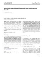
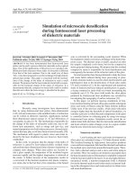
Ablation depths of the target materials as a function of
laser fluence are measured. Figure 1 shows the ablated
depths of Kapton and PET. These values are obtained using a
single laser pulse. It is seen that the results obtained in this
work are close to those reported in the literature.
21,22
Abla-
tion per laser pulse from multiple pulses or overlapping
pulses can be different since the fluence at the machined
surface can be changed due to the divergence of the laser
beam. From the Beer’s Law and data of the ablation depth in
the low laser fluence range, the threshold fluences for Kapton
and PET ablation are found to be around 0.07 and 0.1 J/cm
2
,
respectively. These values are higher than those from the
literature
16,23
and the discrepancies are thought to come from
less data points at low fluences ͑Ͻ1 J/cm
2
͒. The experimental
data are in good agreement with the Beer’s absorption law in
the fluence range between 0.2 and 1.0 J/cm
2
. However, in the
range of high fluences ͑above 1.8 J/cm
2
͒, the measured abla-
tion rate begins to level off. This is due to the strong shield-
ing effect of the laser ejected plume at high laser fluences.
21
The side walls of the excimer laser ablated polymer
structures are usually tapered and the angle varies with the
laser pulse parameters and material properties. The main rea-
son is that, as the ablation depth increases, the wave front has
different intensity distribution. Moreover, the tapered wall
structure leads to significant attenuation of the fluence.
24
Us-
ing a proper laser fluence ͑usually high fluence͒ can reduce
the angle of taper.
25
In order to predict the shape of the walls
of the micromachined structures, a model based on a local
distribution of a beam in the developing structure has been
described.
26
In this work, high laser fluences are used for
fabricating channels with straight walls.
A. Mask patterning
Mask patterning is very similar to lithography. A laser
beam passes through a mask with a prefabricated pattern and
irradiates on the polymer surface by an imaging lens set. In
our system, the ablated patterns are reduced images with
demagnification of around ten. Results of mask patterning,
such as a rectangular channel and a circle with a cross in
PET, are shown in Fig. 2. Figure 2͑a͒ shows microcolumns
whose side is less than 20
m. A slit of 5 mm long and 200
m wide was employed to produce a slot image, and arrays
of slots were imaged in perpendicular directions to fabricate
the column array. This array of columns can be used as a
microfilter in a fluid separation device.
A cross-shaped wall in a circular hole is shown in Fig.
2͑b͒. Nap type patterns on the bottom of PET are obtained.
The nap structure formation on PET has been reported in
several articles.
27,28
This nap structure may assist mixing of
fluids in microfluidic devices. However, it is not preferable in
most applications. Moving the target during laser ablation
can reduce these patterns drastically. It is also suggested that
a well defined pattern can be obtained if a stopping layer
such as a Ti film is applied on the back side of the polymer.
29
The characteristics of the mask projection method can be
summarized as: ͑1͒ complex patterns can be machined with
FIG. 1. Ablation depth per pulse vs fluence: ͑a͒ Kapton and ͑b͒ PET. Ref-
erence data are taken from Refs. 21 and 22, respectively.
FIG. 2. Scanning electron microscope ͑SEM͒ photographs of: ͑a͒ microcol-
umns and ͑b͒ a cross-shape wall in a circle.
256 J. Laser Appl., Vol. 15, No. 4, November 2003 J. Kim and X. Xu
the use of a mask and ͑2͒ batch production is possible with
an array of the same patterns on the mask.
B. Direct laser writing
The other technique for fabricating microstructures is di-
rect laser writing—patterns are created by moving the target
using computer controlled stages. In this work, the image on
the target surface has a rectangular shape with a dimension
of 20ϫ 40
m, a square shape of 20ϫ 20
m, or a circular
shape with a diameter of 20–60
m. The computer con-
trolled stages follow predesigned paths to produce various
types of patterns on the polymer surfaces. The removal rate
can be precisely controlled from the number of laser pulses.
However, to make a smooth pattern, a high pulse repetition
rate and a low scanning velocity are usually necessary. Un-
like mechanical machining, making a blank channel with
moving stages generates tapered geometries at the two ends
of the channel because those places are not irradiated by the
same number of laser pulses compared with the middle part
of the channel as the stage moves.
Figure 3 shows a through channel in PET with smooth
walls and clean edges. It has been observed that at a low
fluence, the wall taper angle is around 3°–10°. However at
high fluences, a reversed taper ͑undercut͒ can be produced.
26
In order to make a straight wall, the fluence has to be con-
trolled within a proper level. In the case of the through chan-
nel shown in Fig. 3, a fluence of 3 J/cm
2
was used which is
higher than the normal fluence level for the polymer ablation
process ͑typically Ͻ0.5 J/cm
2
͒. Figure 4͑a͒ is a simple but
typical microfluidic device: a single microchannel with res-
ervoirs. The channel was ablated by scanning a 20
mby20
m square image and the reservoirs were ablated using mask
patterning. Figure 4͑b͒ shows a cross-shaped microchannel
with two reservoirs, which is a structure typical of chroma-
tography used for enzyme assays performed by combining
chemicals at the cross junction and allowing them to diffu-
sively mix in a reaction channel.
5
III. BONDING TECHNIQUES
The laser machined polymers need to be bonded with
another film or plate such as glass or polymer to be used in a
microfluidic device. Transparent covers are often useful for
optical measurements. If a heating procedure is necessary
during the bonding process, the operating temperature must
not exceed the softening or melting temperature of the poly-
mers. As such, some traditional bonding techniques for
MEMS fabrication are not applicable to polymers due to the
high operation temperatures. In addition, there are several
other requirements for bonding microstructures. The bonding
adhesive layer, if it is used, must be very thin. This is be-
cause the ablated depth of the microstructures can be as
small as a few microns, so it is possible to fill up the micro-
structures when a thick layer of adhesive is applied. There-
fore, the viscosity of adhesive materials must be very low
͑less than 200 cps͒. Two bonding techniques, SOG and IR
laser bonding, are applied in this work and are described as
follows.
A. Spin-on glass bonding
The SOG process was originally developed in the micro-
electronics industry for deposition of silicon oxide during
planarization processes and fabrication of silicon-on-
insulator structures due to good crystallinity on the silicon
surface.
30,31
Yamada et al. reported using SOG for bonding
silicon wafer and silicon nitride.
32
Much research has been
carried out to apply SOG as an adhesive substance for silicon
wafers.
33
The procedure of SOG bonding used in this work is
as follows. First, the cover such as a glass slide is cleaned
with acetone or methanol. Second, the SOG layer was spun
on the glass slide at 2000 rpm for 40 s. The thickness of the
spin coated SOG layer at 2000 rpm was in the range of
490–500 nm. The machined polymer plate or film is then
placed on top of the glass and both parts are cured for 120
min at 200°C. Kapton films can be used in SOG bonding
since the melting temperature of Kapton is 230 °C. Figure 5
FIG. 3. SEM photograph of an excimer laser machined microchannel in
PET.
FIG. 4. ͑a͒ Fluidic channel of 20
m wide with two reservoirs and ͑b͒
cross-shape channel and reservoirs.
257J. Laser Appl., Vol. 15, No. 4, November 2003 J. Kim and X. Xu
shows the top view of a bonded sample, which is used in a
microscale heat exchanger. The Kapton film is completely
bonded to the glass substrate.
B. IR laser bonding
The bonding processes using adhesives may not be ap-
plicable when high optical transmission in the bonding zone
is needed or the melting temperature of the polymer is below
200 °C. Also, release vapors in the hardened adhesives could
be difficult to control in the joining zone.
34
Laser techniques
have been recently developed to bond polymers.
35,36
The
schematic diagram of this process is shown in Fig. 6. The
parts to be bonded consist of a transparent polymer and an
opaque one. The laser beam passes through the transparent
part and is absorbed by the opaque part. Heat is conducted
into the transparent part and the bonding process occurs at
the interface due to melting and resolidification. The experi-
mental setup used in this work consists of a laser source, an
aperture, a lens, and a target holder. A cw fiber laser (
ϭ 1100 nm) is focused on the bonding area with the use of a
lens which has a 200 mm focal length. An aperture is used
for reducing the laser energy to a proper level. Materials are
acrylics: one being clear and the other being opaque. The
processing parameters are summarized in Table I.
Too low laser power can lead to a failure of adhesion and
too high power will cause generation of bubbles at the inter-
face or even burning of the materials. The quality of laser
bonding can be evaluated with several aspects such as the
strength of the joining part, optical properties at the interface,
and the presence of air bubbles, which are determined by the
transient temperature distribution at the bonding zone. The
temperature distribution is related to the amount of radiation
energy absorbed at the opaque surface and the conduction
process in the materials, and can be calculated using a ther-
mal model. Assuming a perfect contact between the plates
͑no air gap͒, the temperature distribution in the material can
be obtained from solving the following one-dimensional heat
conduction equation
c
p
ץ
T
ץ
t
ϭ
ץ
ץ
x
ͩ
k
ץ
T
ץ
x
ͪ
, ͑1͒
where
is the density, c
p
is the specific heat, k is the con-
ductivity, and T is the temperature. The laser intensity input
can be considered as a boundary condition at the interface as
Ϫ k
1
•
ץ
T
1
ץ
x
ϭϪk
2
•
ץ
T
2
ץ
x
ϩ q
Љ
,atxϭ 0. ͑2͒
q is the laser power density absorbed at the interface which
can be evaluated quantitatively with absorptivity, transmis-
sivity, and reflectivity measurements. T
1
and T
2
are tempera-
tures in two polymer layers. The refractive index of the
transparent plate was found to be 1.45Ϫi 1.51ϫ 10
Ϫ 6
, and
the reflective index of opaque one is 1.45Ϫ i 1.88ϫ 10
Ϫ 1
.
Using these values, it is found that 87.52% of incident laser
beam energy is absorbed at the interface.
The solution to the heat conduction equations, Eqs. ͑1͒
and ͑2͒, can be expressed as
37
T
͑
x,t
͒
Ϫ T
i
ϭ
q
Љ
͑
␣
t/
͒
1/2
k
exp
ͩ
Ϫ x
2
4
␣
t
ͪ
Ϫ
q
Љ
x
2k
erfc
ͩ
x
2
ͱ
␣
t
ͪ
,
͑3͒
where
␣
is the thermal diffusivity and T
i
is the initial tem-
perature. The calculated transient temperature profile at vari-
ous locations is shown in Fig. 7. The laser power intensity is
0.42 W/mm
2
. In Fig. 7, the data above 110 °C have no sig-
nificant meaning because the latent heat of phase change is
not considered in the calculation and the material properties
such as reflectivity, transmissivity, and diffusivity are signifi-
cantly different from the values of the solid.
Figure 8͑a͒ shows a laser bonded sample, where3sof
exposure time was used and high quality bonding was
achieved. As shown in Fig. 7, it can be deduced that the
calculated temperature of the interface at this time is around
100 °C, which is near the melting temperature ͑105 °C͒.
Therefore, the results with3softheexposure time are in
agreement with the calculated ones, and it can be concluded
that high quality bonding can be obtained around the melting
temperature. In the experiments, the level of deformation in-
FIG. 5. SOG bonding sample ͑Kapton film on a glass substrate͒.
FIG. 6. Schematic diagram of laser bonding.
TABLE I. Parameters of IR laser bonding.
Power 29.5 mW
Focused laser beam diameter 0.3 mm
Power intensity 0.42 W/mm
2
Aperture diameter up to 4 mm
Focal length of the lens 200 mm
Target position from the lens 240 mm
Exposure time 1–60 s
258 J. Laser Appl., Vol. 15, No. 4, November 2003 J. Kim and X. Xu
creases as the heating time increases. When the laser heating
time exceeds 60 s, bubbles at the interface can be observed.
The bonded spot size changes with parameters such as
the laser beam diameter, the exposure time, and the laser
intensity. If the sample is moved on a stage during laser
irradiation, the laser bonded area can have a line shape or
more complex shapes. Figure 8͑b͒ shows a bonded sample
which is rotated along a circle with a diameter of 5 mm
during bonding. The bonded area has a width of 4 mm and is
shown as the dark ring in the figure.
Comparing SOG bonding versus IR laser bonding, SOG
bonding showed stronger adhesion at the interface compared
with IR bonding, however the rate of successful bonding in
the experiments was low: around 25%. This is due to the fact
that the very thin bonding layer applied to very smooth sur-
faces such as wafers can be disturbed by the relatively rough
surface of polymer materials. On the other hand, it is tech-
nically hard to apply a thin layer on patterned surfaces with
the spin coating process. In this case, the bonding layer is not
uniform and there is also the possibility of filling up the
laser-fabricated patterns with the bonding material, which
usually leads to blockage of the microchannels. In contrast,
IR bonding has a potential in local bonding. However, the
parameters must be chosen carefully to avoid deformation at
the interface and to improve the bonding strength. Extensive
experimental tests, with the aid of the heat transfer model
described above, are necessary to further improve the IR
bonding technique.
IV. EXAMPLE OF A LASER-MACHINED
MICROSYSTEM: A DIFFUSION MICROPUMP
Fabrication of microscale diffusion pumps has been re-
ported in the literature,
38,39
using silicon as the base materials
and employing standard lithography techniques. The sche-
matic diagram of a diffusion micropump is shown in Fig.
9͑a͒. It has an inlet diffuser, an outlet diffuser, and a dia-
phragm. As the diaphragm of the chamber is deformed
downward by an actuator, more fluid flows out through the
outlet nozzle and as it is deformed upward, more fluid enters
through the inlet diffuser. Due to the different flow rates, a
net flow from the inlet diffuser to the outlet diffuser can be
induced. This type of diffusion pump has many advantages.
For example, the valveless operation makes it simple and
reliable.
In this work, Kapton is used as the base material and is
machined by excimer laser ablation. It is expected that the
polymer will allow a larger displacement of the diaphragm,
resulting in higher efficiency. As shown in Fig. 9͑b͒, the inlet
channel, the outlet channel, and the chamber are machined
by laser ablation. The neck of the diffuser channel and the
diffuser length are around 45 and 2450
m, respectively. The
diameter of the chamber, which is covered with another Kap-
ton layer, is 4.5 mm. Bonding with sufficient strength is nec-
essary because the assembled system is subjected to high
pressure liquid. Since SOG bonding shows a stronger bond
compared with IR bonding, it is used here for bonding a
glass substrate with a machined polymer film. The assembled
system is shown in Fig. 9͑c͒. For the purpose of testing, a
pneumatic system is used to actuate the micropump. This
system uses pulsations of high pressure air to actuate the
diaphragm. The observed flow rate at a frequency of 15 Hz is
around 11.5 mm
3
/min. It is also expected that higher flow
rates can be obtained if the diaphragm is actuated at higher
frequencies using a different actuation method such as elec-
trostatic actuation.
FIG. 7. Temperature profile on the opaque side at a laser power intensity of
0.42 W/mm
2
.
FIG. 8. Photograph of laser bonded samples: ͑a͒ a top view of a bonded spot
and ͑b͒ circular bonding.
FIG. 9. ͑a͒ Schematic of the pump in a top view, ͑b͒ the laser fabricated
diffuser of the pump, and ͑c͒ the assembled pump.
259J. Laser Appl., Vol. 15, No. 4, November 2003 J. Kim and X. Xu
V. CONCLUSIONS
Laser techniques for fabricating microfluidic devices us-
ing polymer as the base material were presented. The mask
patterning method is simple and rapid to fabricate repeated
microstructures. Thus, it has advantages for batch production
and fast patterning. On the other hand, direct laser writing
with computer controlled moving stages can provide rapid
changes of patterns. The combination of these two tech-
niques can be used as a versatile tool for fabricating various
microdevices on polymers. Techniques for bonding polymers
were also studied. The SOG process led to a tight bonding of
glass and polymer, and IR laser bonding can be used for
microbonding on local areas of MEMS devices. A diffuser
micropump was fabricated as a demonstration of laser fabri-
cation of polymer based microsystems.
ACKNOWLEDGMENT
This work is supported by the Integrated Detection of
Hazardous Materials ͑IDHM͒ Program, a Department of De-
fense project managed jointly by Center for Sensing Science
and Technology, Purdue University, and Naval Surface War-
fare Center, Crane, Indiana.
1
A. S. Holmes and S. M. Saidam, ‘‘Sacrificial layer process with laser-
driven release for batch assembly operations,’’ J. Microelectromech. Syst.
7, 416–422 ͑1998͒.
2
M. Lapczyna and M. Stuke, ‘‘Rapid prototype fabrication of smooth mi-
croreactor channel systems in PMMA by VUV laser ablation at 157 nm
for applications in genome analysis and biotechnology,’’ Mater. Res. Soc.
Symp. Proc. 526, 143–148 ͑1998͒.
3
R. Vaidya, L. M. Tender, G. Bradley, M. J. O’Brien II, M. Cone, and G. P.
Lopez, ‘‘Computer-controlled laser ablation: a convenient and versatile
tool for micropatterning biofunctional synthetic surfaces for applications
in biosensing and tissue engineering,’’ Biotechnol. Prog. 14, 371–377
͑1998͒.
4
M. S. Talary, J. P. H. Burt, N. H. Rizvi, P. T. Rumsby, and R. Pethig,
‘‘Microfabrication of biofactory-on-a-chip devices using laser ablation
technology,’’ Proc. SPIE 3680, 572–580 ͑1999͒.
5
S. A. Zugel, B. J. Burke, F. E. Regnier, and F. E. Lytle, ‘‘Electrophoreti-
cally mediated microanalysis of leucine aminopeptidase using two-photon
excited fluorescence detection on a microchip,’’ Anal. Chem. 72, 5731–
5735 ͑2000͒.
6
B. He, N. Tait, and F. Regnier, ‘‘Fabrication of nanocolums for liquid
chromatography,’’ Anal. Chem. 70, 3790–3797 ͑1998͒.
7
B. He, L. Tan, and F. Regnier, ‘‘Microfabricated filters for microfluidic
analytical systems,’’ Anal. Chem. 71, 1464–1468 ͑1999͒.
8
R. Srinivasan and V. Mayne-Banton, ‘‘Self-developing photoetching of
poly͑ethylene terephthalate͒ films by far-ultraviolet excimer laser radia-
tion,’’ Appl. Phys. Lett. 41, 576–578 ͑1982͒.
9
R. Srinivasan and B. Braren, ‘‘Ultraviolet laser ablation of organic poly-
mers,’’ Chem. Rev. 89, 1303–1316 ͑1989͒.
10
G. D. Mahan, H. S. Cole, Y. S. Liu, and H. R. Philipp, ‘‘Theory of poly-
mer ablation,’’ Appl. Phys. Lett. 53, 2377–2379 ͑1988͒.
11
E. Sutcliffe and R. Srinivasan, ‘‘Dynamics of UV laser ablation of organic
polymer surfaces,’’ J. Appl. Phys. 60, 3315–3322 ͑1986͒.
12
J. E. Andrew, P. E. Dyer, D. Forster, and P. H. Key, ‘‘Direct etching of
polymer materials using a XeCl Laser,’’ Appl. Phys. Lett. 43, 717–719
͑1983͒.
13
B. Hopp, M. Csete, K. Revesz, J. Vinko, and Zs. Bor, ‘‘Formation of the
surface structure of polyethylene-terephtalate ͑PTE͒ due to ArF excimer
laser ablation,’’ Appl. Surf. Sci. 96–98, 611–616 ͑1996͒.
14
S. Lazare and R. Srinivasan, ‘‘Surface properties of poly͑ethylene tereph-
thalate͒ films modified by far-ultraviolet radiation at 193 nm ͑laser͒ and
185 nm ͑low intensity͒,’’ J. Phys. Chem. 90, 2124–2131 ͑1986͒.
15
D. Praschak, T. Bahners, and E. Schollmeyer, ‘‘PET surface modifications
by treatment with monochromatic excimer UV lamps,’’ Appl. Phys. A:
Mater. Sci. Process. 66, 69–75 ͑1998͒.
16
J. H. Brannon, J. R. Lankard, A. I. Baise, F. Burns, and J. Kaufman,
‘‘Excimer laser etching of polymers,’’ J. Appl. Phys. 58, 2036–2043
͑1985͒.
17
H. Watanabe and M. Yamamoto, ‘‘Laser ablation of poly͑ethylene tereph-
thalate͒,’’ J. Appl. Polym. Sci. 64, 1203–1209 ͑1997͒.
18
F. Wagner and P. Hoffmann, ‘‘Novel structure formation in poly͑ethylene
therephthalate͒ by scanning excimer laser ablation,’’Appl. Surf. Sci. 154–
155, 627–632 ͑2000͒.
19
J. P. Rossier, P. Bercier, A. Schwarz, S. Loridant, and H. H. Girault,
‘‘Topography, crystallinity and wettability of photoablated PET surfaces,’’
Langmuir 15, 5173–5178 ͑1999͒.
20
W. Pfleging, T. Hanemann, W. Bernauer, and M. Torge, ‘‘Laser microma-
chining of mold inserts for replication techniques—state of the art and
applications,’’ Proc. SPIE 4274, 331–345 ͑2001͒.
21
G. H. Pettit and R. Sauerbrey, ‘‘Pulsed ultraviolet laser ablation,’’ Appl.
Phys. A: Solids Surf. 56,51–63͑1993͒.
22
E. C. Harvey, T. R. Mackin, B. C. Dempster, and R. E. Scholten, ‘‘Micro-
optical structures for atom lithography studies,’’ Proc. SPIE 3892, 266–
273 ͑1999͒.
23
S. Lazare and P. Benet, ‘‘Surface amorphization of Mylar films with the
excimer laser radiation above and below ablation threshold: ellipsometric
measurements,’’ J. Appl. Phys. 74, 4953–4957 ͑1993͒.
24
S. Lazare, J. Lopez, and F. Weisbuch, ‘‘High-aspect-ratio microdrilling in
polymeric materials with intense KrF laser radiation,’’ Appl. Phys. A:
Mater. Sci. Process. 69, S1–S6 ͑1999͒.
25
T. W. Hodapp and P. R. Fleming, ‘‘Modeling topology formation during
laser ablation,’’ J. Appl. Phys. 84, 577–583 ͑1998͒.
26
C. Paterson, A. S. Holmes, and R. W. Smith, ‘‘Excimer laser ablation of
microstructures: a numerical model,’’ J. Appl. Phys. 86, 6538–6546
͑1999͒.
27
E. Arenholz, V. Svorcik, T. Kefer, J. Heitz, and D. Bauerle, ‘‘Structure
formation in UV-laser ablated poly-ethylene-terephthalate ͑PET͒,’’ Appl.
Phys. A: Solids Surf. 53, 330–331 ͑1991͒.
28
F. Wagner and P. Hoffmann, ‘‘Structure formation in excimer laser abla-
tion of stretched poly͑ethylene therephthalate͒͑PET͒: the influence of
scanning ablation,’’ Appl. Phys. A: Mater. Sci. Process. 69, S841–S844
͑1999͒.
29
T. Klotzbucher, T. Braune, S. Sigloch, J. Hoßfeld, M. Neumeier, H. Bauer,
and W. Ehrfeld, ‘‘Polymer microsystems by excimer laser ablation: from
rapid prototyping to large number fabrication,’’Proc. SPIE 4274, 307–315
͑2001͒.
30
H. J. Quenzer, C. Dell, and B. Wagner, ‘‘Silicon–silicon anodic-bonding
with intermediate glass layers using spin-on glasses,’’ Proceedings IEEE
Micro Electro Mechanical Systems, San Diego, CA, 1996, pp. 272–276.
31
A. Yamada, T. Kawasaki, and M. Kawashima, ‘‘SOI by wafer bonding
with spin-on glass as adhesive,’’ Electron. Lett. 23,39–40͑1987͒.
32
A. Yamada, T. Kawasaki, and M. Kawashima, ‘‘Bonding silicon wafer to
silicon nitride with spin-on glass as adhesive,’’ Electron. Lett. 23,314–
315 ͑1987͒.
33
M. Alexe, V. Dragoi, M. Reiche, and U. Gosele, ‘‘Low temperature
GaAs/Si direct wafer bonding,’’ Electron. Lett. 36, 677–678 ͑2000͒.
34
R. A. Grimm, ‘‘Through-transmission infrared welding of polymers,’’ Pro-
ceedings of the Society of Plastic Engineers Annual Technical
Conference—ANTEC 1996, Indianapolis, IN, Vol. 1, pp. 1238–1244.
35
H. Potente, J. Korte, and F. Becker, ‘‘Laser transmission welding of ther-
moplastics: analysis of the heating phase,’’ J. Reinf. Plast. Compos. 18,
914–920 ͑1999͒.
36
T. Ebert, ‘‘Keeping a clear view joining transparent plastics by laser,’’
Kunststoffe Plast. Europe 89, 17–18 ͑1999͒.
37
F. P. Incropera and D. P. DeWitt, Fundamentals of Heat and Mass Trans-
fer, 4th ed. ͑Wiley, New York, 1996͒, pp. 236–240.
38
P. Gravesen, J. Branebjerg, and O. S. Jensen, ‘‘Microfluidics—a review,’’
J. Micromech. Microeng. 3, 168–182 ͑1993͒.
39
S. Shoji and M. Esashi, ‘‘Microflow devices and systems,’’ J. Micromech.
Microeng. 4, 157–171 ͑1994͒.
260 J. Laser Appl., Vol. 15, No. 4, November 2003 J. Kim and X. Xu