plasma formation in fused silica induced by loosely focused femtosecond laser pulse
Bạn đang xem bản rút gọn của tài liệu. Xem và tải ngay bản đầy đủ của tài liệu tại đây (160.6 KB, 3 trang )
Plasma formation in fused silica induced by loosely focused femtosecond
laser pulse
Alexander Q. Wu, Ihtesham H. Chowdhury, and Xianfan Xu
a͒
School of Mechanical Engineering, Purdue University, West Lafayette, Indiana 47907
͑Received 27 June 2005; accepted 26 January 2006; published online 15 March 2006͒
The focusing position inside fused silica irradiated by a loosely focused high power femtosecond
laser pulse is studied both experimentally and numerically. The experimental measurement of
plasma radiation shows that the laser pulse is focused behind the focal plane, which is also found
in the numerical calculation and is attributed to a complex interplay between self-focusing due to the
Kerr effect and defocusing because of the free electron plasma. Also, when more than one pulse is
incident at the same spot in the sample, plasma radiation is observed at more than one spot along
the laser propagation direction. © 2006 American Institute of Physics. ͓DOI: 10.1063/1.2183361͔
Femtosecond lasers have been proposed to microma-
chine transparent materials for fabricating waveguides,
1,2
op-
tical gratings,
3,4
and other photonic devices.
5,6
These appli-
cations require a good understanding of the laser beam
propagation and absorption inside the transparent materials.
The dynamics of femtosecond laser propagation in transpar-
ent materials like fused silica is extremely complicated as the
high intensity of the laser pulses leads to nonlinear effects
such as self-focusing and creation of free electron plasma by
nonlinear photoionization. Self-focusing occurs when the la-
ser power exceeds a critical power P
cr
and can lead to cata-
strophic damage.
7
The free-electron plasma leads to absorp-
tion of the pulse and also defocusing. The competition
between these processes coupled with other effects like
group velocity dispersion lead to rich pulse propagation phe-
nomena such as pulse splitting,
8,9
filamentation,
10,11
and
white light generation.
12
Plasma radiation perpendicular to
the laser propagation direction has been used as a real-time
measurement method to study the free electron distribution
13
and the optical breakdown in fused silica.
14,15
The experi-
ments of optical breakdown shows that the laser beam is
focused near the focal plane when the laser energy is not
very high.
14,15
In this letter, we report focusing behind the focal plane
inside fused silica by loosely focused femtosecond laser
pulses with high power, up to 500 times the self-focusing
critical power P
cr
ϳ2 MW. Such a laser condition is used,
for example, for laser modification of internal structures of
optical materials. Plasma radiation is measured and related to
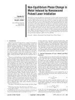
the calculated free electron distribution. The schematic of the
experimental setup is shown in Fig. 1. A Spectra-Physics
Spitfire regenerative amplifier system is used to produce
90 fs ͑full width at half maximum͒ pulses centered at
800 nm at a repetition rate of 0.5 kHz with a maximum en-
ergy of 1 mJ. An electronic shutter ͑Uniblitz LS6T2͒ is used
to select single pulses and a half-wave-plate-polarizer com-
bination is used to control the pulse energy. The pulses are
loosely focused ͓i.e., using a small numerical aperture ͑NA͔͒
inside fused silica by a 60 mm focal length lens, which is
able to focus the laser beam into a 40
m diam spot in air.
The focal length along with the nominal beam diameter of
4 mm yields a NA of about 0.03. Samples are 6.35 mm thick
fused silica ͑Corning 7980͒ which are optically polished on
all sides. The samples are cleaned with methanol and acetone
prior to laser irradiation and all the experiments are carried
out in air at atmospheric pressure. The plasma radiation is
observed from the side of the sample by using an imaging
system consisting of a 0.28 NA long-working distance Mitu-
toyo 10X objective, a 200 mm focal length tube lens, and a
charge coupled device camera. The camera is connected to a
frame-grabber card on a computer to enable the acquisition
of single-shot images. A filter is placed in front of the camera
to block any scattered 800 nm light.
The numerical model used to compute femtosecond
pulse absorption and propagation dynamics has been de-
scribed in detail elsewhere.
16
Briefly, the linearly polarized
laser pulse propagating is modeled using a 2͑spatial͒
+1͑temporal͒ dimensional wave propagation equation
coupled with a rate equation for the free electron density.
The generation of free electrons is predicted from the
Keldysh theory which includes both multiphoton ionization
and tunneling photoionization.
17
The propagation equation
takes into account the effects of diffraction, group velocity
dispersion, and laser energy absorption. Defocusing due to
the free electron plasma and self-focusing because of the
Kerr effect are simultaneously accounted for by computing
the dielectric constant based on the Drude model. The equa-
tions are solved numerically using a Crank–Nicholson finite-
differencing scheme to yield the spatial and temporal distri-
bution of the laser intensity inside fused silica and the free
electron densities.
a͒
Electronic mail: FIG. 1. Experimental setup for measurement of plasma radiation.
APPLIED PHYSICS LETTERS 88, 111502 ͑2006͒
0003-6951/2006/88͑11͒/111502/3/$23.00 © 2006 American Institute of Physics88, 111502-1
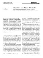
Downloaded 13 Dec 2007 to 128.46.193.173. Redistribution subject to AIP license or copyright; see />Figure 2 shows the recorded images of plasma radiation
when the sample is irradiated by a single pulse ͓Fig. 2͑a͔͒,
two pulses ͓Fig. 2͑b͔͒, and three pulses ͓Fig. 2͑c͔͒ with 70
and 80
J/pulse incident on the same spot. The laser pulse
propagates from left to right in the image. The white dashed
vertical lines represent the position of the focal plane in the
absence of any nonlinear phenomena, which is behind the
front surface at z = 1453
m ͑the sample surface is at z =0͒.
Plasma radiation is seen at a position behind the focal plane,
and it shifts forward with increase in incident laser energy.
Plasma formation behind the focal plan is due to the
competition between the defocusing and self-focusing of the
femtosecond pulse, which is also observed from the results
of the numerical simulation of free electron density. Figures
3͑a͒ and 3͑b͒ represent the radial dependence of normalized
time-integrated free electron density and normalized energy
flux at four different positions along the laser propagation
direction, with incident laser energy of 80
J/pulse. In the
absence of any nonlinear effect, the laser beam diameter
should remain almost constant inside the sample since under
the focusing condition described above, the Rayleigh length
is about 2.3 mm. However, it is seen that the laser pulse is
defocused strongly near the surface—the beam is wider at
z=5
m than that at surface, z =0
m. At z=90
m, the
Gaussian shape of the laser beam is distorted into a top-hat
shape. The defocusing is due to the dense free electron
plasma
18
formed in the target. Figures 4͑a͒ and 4͑b͒ show the
z position dependence of transmissivity, and the time inte-
grated free electron density at the beam center. It is seen that
very dense free electron plasma is formed close to the sample
surface, and its density drops quickly within 5
m because
of the strong absorption and defocusing. For zϾ90
m, the
laser intensity as well as the free electron density are greatly
reduced, leading to a focusing condition due to the dominant
self-focusing effect and shrinkage of the laser beam diameter
as shown in Fig. 3. The cumulative effect of defocusing and
self-focusing results in the laser beam being focused behind
the focal point as shown in Fig. 4͑b͒, which shows the free
electron density peaks behind the focal plane ͑the dashed
vertical line, z=1453
m͒. Note that the plot for z
Ͼ 600
m is magnified by 250 times for clarity.
In order to further clarify the defocusing effect of the
dense free electron plasma, Fig. 5 shows the image of time-
integrated plasma radiation generated by a single pulse fo-
cused on the sample surface marked by the dashed white
line. The incident laser energy is 80
J/pulse. Figure 5
clearly shows that the plasma is defocused strongly within
30
m below the surface, although the Rayleigh length is
around 2.3 mm. Some scattering of light, right to the dashed
line, can be seen inside the fused silica. The radiation in air
FIG. 2. ͑Color online͒ Experimental plasma radiation for the case of: ͑a͒
single pulse, ͑b͒ two pulses, and ͑c͒ three pulses with 70 and 80
J each
incident on the same spot.
FIG. 3. Simulation results of normalized, radial position dependence of: ͑a͒
time integrated free electron density and ͑b͒ energy flux. The laser energy is
80
J/pulse.
FIG. 4. Simulation results of z position dependence of ͑a͒ transmissivity and
͑b͒ time integrated free electron density at the beam center. The laser energy
is 80
J/pulse.
FIG. 5. ͑Color online͒ Experimental plasma radiation of single pulse fo-
cused on sample surface with 80
J/pulse.
111502-2 Wu, Chowdhury, and Xu Appl. Phys. Lett. 88, 111502 ͑2006͒
Downloaded 13 Dec 2007 to 128.46.193.173. Redistribution subject to AIP license or copyright; see />͑left to the sample surface͒ is due to the expansion of the
high dense plasma formed on the surface.
The above description of self-focusing and defocusing is
qualitatively explained with the density of free electron
plasma. In reality, there is complex interplay of self-
focusing, defocusing, group velocity dispersion, and diffrac-
tion which are all considered in the numerical model. Experi-
mentally, it is observed that the plasma radiation does occur
at about 150
m after the focal plane as shown in Fig. 2͑a͒,
and location of plasma formation moves forward as the laser
energy increases. The simulation results are not compared
with the experimental data quantitatively as both the detailed
formation of plasma radiation from the free electron plasma
and the effect of air on the laser beam propagation before the
sample are not considered in the simulation model.
In experiments, it is also observed that when more than
one pulse is incident at the same spot on the sample, plasma
radiation occurs at more than one location inside the sample,
resembling a filament broken up into multiple fragments.
This is shown in Figs. 2͑b͒ and 2͑c͒ which show the plasma
radiation measurements when the second and the third pulse
hit the sample. The multiple plasma radiation spots can prob-
ably be attributed to the creation of defect states or damage
by the preceding pulse inside the sample and the modifica-
tion near the surface as the incident laser energy is above the
damage threshold value. The subsequent pulses are absorbed
more strongly in these positions leading to enhanced plasma
radiation. This in turn leads to greater damage at these posi-
tions and therefore the plasma is observed to grow toward
the surface of the sample when multiple pulses are allowed
to hit the same spot.
In summary, the plasma radiation measurements and nu-
merical simulation of free electron density revealed the com-
plex nature of femtosecond pulse propagation in fused silica.
Due to the various nonlinear effects like self-focusing of the
Kerr effect and defocusing due to the free electron plasma,
the laser pulse is focused behind the focal plane. It was also
seen that in the case of irradiation with multiple pulses, the
preceding pulses create defect and damage that can alter the
absorption and propagation characteristics of the succeeding
pulses.
Support of this work by the National Science Foundation
and the Indiana 21st Century Research and Development
Fund is gratefully acknowledged.
1
A. M. Kowalevicz, V. Sharma, E. P. Ippen, J. G. Fujimoto, and K.
Minoshima, Opt. Lett. 30, 1060 ͑2005͒.
2
A. Saliminia, N. T. Nguyen, M. C. Nadeau, S. Petit, S. L. Chin, and R.
Vallee, J. Appl. Phys. 93, 3724 ͑2003͒.
3
Q. Wu, Y. Ma, R. Fang, Y. Liao, Q. Yu, X. Chen, and K. Wang, Appl.
Phys. Lett. 82, 1703 ͑2003͒.
4
S. J. Mihailov, C. W. Smelser, D. Grobnic, R. B. Walker, P. Lu, H. M.
Ding, and J. Unruh, J. Lightwave Technol. 22,94͑2004͒.
5
M. Li, K. Mori, M. Ishizuka, X. Liu, Y. Sugimoto, N. Ikeda, and K.
Asakawa, Appl. Phys. Lett. 83, 216 ͑2003͒.
6
M. Ventura, M. Straub, and M. Gu, Appl. Phys. Lett. 82,1649͑2003͒.
7
R. W. Boyd, Nonlinear Optics ͑Academic, San Diego, 1992͒, Sec. 6.2.
8
J. K. Ranka, R. W. Schirmer, and A. L. Gaeta, Phys. Rev. Lett. 77,3783
͑1996͒.
9
A. A. Zozulya, S. A. Diddams, A. G. Van Engen, and T. S. Clement, Phys.
Rev. Lett. 82, 1430 ͑1999͒.
10
L. Sudrie, A. Couairon, M. Franco, B. Lamouroux, B. Prade, S.
Tzortzakis, and A. Mysyrowicz, Phys. Rev. Lett. 89, 186601 ͑2002͒.
11
L. Berge, S. Skupin, F. Lederer, G. Mejean, J. Yu, J. Kasparian, E.
Salmon, J. P. Wolf, M. Rodriguez, L. Woste, R. Bourayou, and R.
Sauerbrey, Phys. Rev. Lett. 92, 225002 ͑2004͒.
12
A. L. Gaeta, Phys. Rev. Lett. 84, 3582 ͑2000͒.
13
Z. Wu, H. Jiang, Q. Sun, H. Yang, and Q. Gong, Phys. Rev. A 68, 063820
͑2003͒.
14
N. T. Nguyen, A. Saliminia, W. Liu, S. L. Chin, and R. Vallée, Opt. Lett.
28, 1591 ͑2003͒.
15
A. Saliminia, N. T. Nguyen, S. L. Chin, and R. Vallée, Opt. Commun.
241, 529 ͑2004͒.
16
A. Q. Wu, I. H. Chowdhury, and X. Xu, Phys. Rev. B 72, 085128 ͑2005͒.
17
L. V. Keldysh, Sov. Phys. JETP 20, 1307 ͑1965͒.
18
S. C. Rae and K. Burnett, Phys. Rev. A 46, 1084 ͑1992͒.
111502-3 Wu, Chowdhury, and Xu Appl. Phys. Lett. 88, 111502 ͑2006͒
Downloaded 13 Dec 2007 to 128.46.193.173. Redistribution subject to AIP license or copyright; see />