finite element analysis of pulsed
Bạn đang xem bản rút gọn của tài liệu. Xem và tải ngay bản đầy đủ của tài liệu tại đây (125.25 KB, 6 trang )
X. Richard Zhang
Xianfan Xu
1
e-mail:
School of Mechanical Engineering,
Purdue University,
West Lafayette, IN 47907-1288
Finite Element Analysis of Pulsed
Laser Bending: The Effect of
Melting and Solidification
This work developes a finite element model to compute thermal and thermomechanical
phenomena during pulsed laser induced melting and solidification. The essential elements
of the model are handling of stress and strain release during melting and their retrieval
during solidification, and the use of a second reference temperature, which is the melting
point of the target material for computing the thermal stress of the resolidified material.
This finite element model is used to simulate a pulsed laser bending process, during which
the curvature of a thin stainless steel plate is altered by laser pulses. The bending angle
and the distribution of stress and strain are obtained and compared with those when
melting does not occur. It is found that the bending angle increases continulously as the
laser energy is increased over the melting threshold value. ͓DOI: 10.1115/1.1753268͔
1 Introduction
Laser bending ͑or laser forming͒ is a non-contact technique
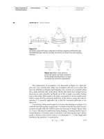
capable of achieving very high precision. The schematic of a laser
bending process is illustrated in Fig. 1. A target is irradiated by a
focused laser beam passing across the target surface. Heating and
cooling cause plastic deformation in the laser-heated area, thus
change the curvature of the target permanently. The mechanism of
laser bending has been explained by the thermo-elasto-plastic
theory, ͓1–3͔. Three laser bending mechanisms, i.e., the tempera-
ture gradient mechanism, the buckling mechanism, and the upset-
ting mechanism have been discussed in the literature, ͓4,5͔. For
the temperature gradient mechanism, a sharp temperature gradient
is generated by laser irradiation and the residual compressive
strain causes permanent bending deformation toward the direction
of the incoming laser beam. Most of the pulsed laser bending
processes are attributed to the temperature gradient mechanism
since the short pulse heating duration induces a very sharp tem-
perature gradient near the target surface.
Using a pulsed laser for bending is of particular interest in the
micro-electronics industry, where high precision bending, curva-
ture adjustment, and alignment are often required. Chen et al. ͓6͔
achieved bending precision on the order of sub-microradian on
stainless steel and ceramics targets, which is higher than any other
bending techniques. The relations between the bending angle and
laser processing parameters were studied with the use of a two-
dimensional finite element method, ͓7͔. In that study, the laser
energy was controlled so that no melting and solidification hap-
pened during the bending process. However, in some laser bend-
ing processes where larger bending angles are needed, the laser
energy used could be high enough to cause melting, ͓8͔.
The finite element method is a general and powerful tool for
investigating the complex thermal and thermomechanical prob-
lems involved in laser bending, ͓9–12͔. When an unconstrained
material melts, its stress and strain will be completely released,
and then begin to retrieve when solidification starts. In this re-
spect, the main challenge of simulations is the handling of the
stress and strain release and retrieval during melting and solidifi-
cation. The stress release is usually approximated by specifying
the temperature dependent material properties, for example, de-
creasing Young modulus and yield strength significantly near the
melting point, ͓9–12͔. On the other hand, the strain release is
hardly being considered due to the difficulty involved in the nu-
merical simulation.
In this paper, a finite element model for simulating pulsed laser
bending involving melting and solidification is developed using
the uncoupled thermal and thermomechanical theory. It is as-
sumed that the pulsed laser beam is uniform across the width of
the specimen ͑the x-direction in Fig. 1͒. Thus, a two-dimensional
thermal-stress model can be applied, which greatly reduces the
computational time. In order to release and retrieve the stress and
strain during melting and solidification, the element removal and
reactivation method is applied to each melted element. In addi-
tion, in order to compute the stress of the solidified element cor-
rectly, a second reference temperature for the thermal stress cal-
culation is used. The bending angle, residual stress, and residual
strain are obtained and compared with the results of pulsed laser
bending without melting.
2 Simulation Procedure
In order to calculate laser bending, a thermal analysis and a
stress and strain analysis are needed, which are considered as
uncoupled since the heat dissipation due to plastic deformation is
negligible compared with the heat provided by laser irradiation. In
an uncoupled thermomechanical model, a transient temperature
field is obtained first in the thermal analysis, and is then used as a
thermal loading in the subsequent stress and strain analysis to
obtain the transient stress, strain, and displacement distributions.
The finite element code, ABAQUS ͑HKS, Inc., Pawtucket, RI͒ is
used. As shown in Fig. 2, a dense mesh is generated around the
laser path and then stretched away in the length and thickness
directions ͑the y and z-directions͒. The domain size and laser pa-
rameters used in the simulations are given in Table 1. The same
mesh is used for both the thermal and stress analyses. A total of
1200 elements are used in the mesh. Mesh tests are conducted by
increasing the number of elements until the calculation result is
independent of the mesh density.
2.1 Thermal Analysis. The thermal analysis is based on
solving the two-dimensional heat conduction equation:
c
˜
ץ
T
ץ
t
ϭ ٌ•
͑
kٌT
͒
ϩ Q
˙
ab
(1)
1
To whom correspondence should be addressed.
Contributed by the Applied Mechanics Division of T
HE AMERICAN SOCIETY OF
MECHANICAL ENGINEERS for publication in the ASME JOURNAL OF APPLIED ME-
CHANICS. Manuscript received by the ASME Applied Mechanics Division, Aug. 29,
2001; final revision, June 30, 2003. Associate Editor: B. M. Moran. Discussion on
the paper should be addressed to the Editor, Prof. Robert M. McMeeking, Journal of
Applied Mechanics, Department of Mechanical and Environmental Engineering Uni-
versity of California–Santa Barbara, Santa Barbara, CA 93106-5070, and will be
accepted until four months after final publication of the paper itself in the ASME
J
OURNAL OF APPLIED MECHANICS.
Copyright © 2004 by ASMEJournal of Applied Mechanics MAY 2004, Vol. 71 Õ 321
where k is the thermal conductivity,
is the density of the stain-
less steel, c
˜
is the derivative of the enthalpy with respect to tem-
perature, and Q
˙
ab
is the volumetric heat source term resulted from
irradiation of a laser pulse. The temperature-dependent properties
of stainless steel 301, ͓13͔, are used in the calculation.
The parameter c
˜
is equal to the specific heat c
p
in solid and
liquid regions. When an impure metal, like stainless steel, is
heated from a solid state, it begins to melt at the solidus tempera-
ture T
s
and melts completely at the liquidus temperature T
l
.In
the mushy zone, i.e., the region where the temperature is between
T
s
and T
l
, c
˜
is defined by
c
˜
ϭ c
p
ϩ
L
T
l
Ϫ T
s
(2)
where L is the latent heat. Values of T
s
, T
l
, and L of stainless
steel 301 are listed in Table 2, ͓13͔. By using c
˜
, the effective
specific heat, the phase change problem can be solved within a
single domain. Solid and liquid material are treated as one con-
tinuous region and the phase boundary does not need to be calcu-
lated explicitly, ͓10͔.
The laser intensity is uniform in the x-direction and has a
Gaussian distribution in the y-direction, expressed as
I
s
͑
y,t
͒
ϭ I
0
͑
t
͒
e
Ϫ 8y
2
/w
2
(3)
where I
0
(t) is the time-dependent laser intensity at the center of
the laser beam and w is the laser beam width at the target surface.
The temporal profile of the laser intensity is treated as increasing
linearly from zero to the maximum at 60 ns, then decreasing lin-
early to zero at the end of the pulse at 120 ns. Therefore, the
volumetric heat source Q
˙
ab
in Eq. ͑1͒ can be expressed as
Q
˙
ab
ϭ
͑
1Ϫ R
f
͒
␣
I
0
͑
t
͒
e
Ϫ 8y
2
/w
2
e
Ϫ
␣
z
(4)
where R
f
is the optical reflectivity measured to be 0.66 for the
stainless steel specimens.
␣
is the absorption coefficient given by
␣
ϭ4
/. The imaginary part of the refractive index
of stain-
less steel 301 at the laser wavelength 1.064
m is unknown, and
ϭ4.5 of iron is used. The initial condition is that the whole
specimen is at the room temperature ͑300 K͒. Since the left and
right boundaries as well as the bottom surface are far away from
the laser irradiated area, the boundary conditions at these bound-
aries are prescribed as the room temperature. Convection and ra-
diation with the surrounding are neglected.
Analyses are carried out with the laser pulse energy of 260
J,
270
J, 280
J, and 300
J, respectively. The peak temperature
obtained by a 270
J pulse is 1703 K, higher than the liquidus
temperature T
l
͑1693 K͒. For comparison, thermal analyses of
three cases without melting are also performed; the laser pulse
energies are 200
J, 230
J, and 250
J, respectively. The peak
temperature obtained by a 250
J pulse is 1649 K, lower than the
solidus temperature T
s
͑1673 K͒.
2.2 Stress and Strain Analyses. In the stress and strain
analysis, the material is assumed to be linearly elastic-perfectly
plastic. The Von Mises yield criterion is used to model the onset
of plasticity. The left edge is completely constrained, and all other
boundaries are force-free. Eight-node biquadratic plane-strain el-
ements are employed.
As in the thermal analysis, the temperature dependent material
properties are used, ͓13͔. Poisson’s ratio of stainless steel AISI
304, ͓14͔, is used. Considering the incompressibility in the liquid
phase, the Poisson ratio of 0.4999 is used when the temperature is
higher than T
s
. The strain rate enhancement effect is neglected
since temperature dependent data are unavailable. Sensitivity of
unknown material properties on the computational results has
been discussed by Chen et al. ͓7͔.
2.3 The Method of Element Removal and Reactivation
In order to model the phenomena of melting and solidification, the
element removal and reactivation method, ͓15͔, is applied. An
element will be excluded from the stress and strain analysis when
its temperature is higher than T
s
, i.e., the element is removed
from the domain after being melted and its stress and strain are
released to zero. During cooling, the removed elements are reac-
tivated in the calculation when their temperatures are lower than
T
s
and the stress and strain start to retrieve.
For the elements starting to solidify, the initial temperature for
the thermal stress calculation T
i
is replaced with a new initial
temperature equal to the temperature at the moment when it is
reactivated, i.e., T
s
. This procedure is carried out for each ele-
ment experiencing melting and solidification with the aid of the
temperature history data obtained from the thermal analysis.
The reason for using a new initial temperature for a reactivated
element is explained as follows. As mentioned before, the thermal
stain of an unconstrained element is totally released after it melts.
During solidification, the thermal strain will change gradually
only if T
s
is used as the initial temperature. Otherwise, if the room
temperature T
i
is still used as the initial temperature, the thermal
strain will experience a sharp jump from zero to a high value,
which is physically incorrect. Therefore, two initial temperatures
should be used for each element involving melting and solidifica-
tion.
The element removal and reactivation would not affect the ther-
mal analysis since the thermal and the stress analysis are not
coupled, and the thermal analysis is performed before the stress
analysis. The forces in the element reaching the melting point are
reduced to zero gradually before the element is removed, which is
determined by the temperature-dependent stress-strain relations.
Therefore, there is no sudden change of stress in elements in-
volved in phase change. On the other hand, when the element is
reactivated with zero stress, it exerts no nodal forces on the sur-
Fig. 1 Schematic of the laser bending process
Fig. 2 Computational mesh
Table 1 Domain size and pulsed laser parameters
Specimen length ͑y͒ 600
m
Specimen thickness ͑z͒ 100
m
Laser wavelength 1.064
m
Laser pulse full width 120 ns
Laser pulse energy 200–300
J
Laser line width 30
m
Laser line length 1.3 mm
Table 2 Thermal properties of stainless steel 301
Solidus temperature, T
s
1673 K
Liquidus temperature, T
l
1693 K
Latent heat, L 265 J/g
322 Õ Vol. 71, MAY 2004 Transactions of the ASME
rounding elements. Thus the element removal and reactivation do
not have any adverse effect on the thermal and stress calculation.
Based on the above description, the stress and strain for the
elements involved in phase change are computed by the method of
element removal and reactivation and the use of a new initial
temperature at T
s
to calculate the stress/strain of the solidified
elements. During the calculation, element removal and reactiva-
tion are tracked for each element since each melted element be-
gins to melt and solidify at different times. Hence, the computa-
tion is intensive even for the two-dimensional problem considered
in this work.
3 Results and Discussion
Calculations are first conducted to verify the finite element
analysis of melting and solidification. Results of finite element
analysis are compared with exact solutions of solidification and
melting problems given by Carslaw and Jaeger ͓16͔. For the so-
lidification case, the target is initially at the liquid state with a
uniform temperature. At tϭ 0, the temperature at the surface (x
ϭ 0) is changed and held at a temperature lower than the melting
point. Freezing thus starts and proceeds into the material. The
position of the solid-liquid interface
␦
can be calculated with
known material properties, and its expression is given in the insert
of Fig. 3͑a͒. Figure 3͑a͒ shows the comparison of the results. It
can be seen that the result of the finite element analysis matches
exactly with the analytical solution. Similarly, results of the melt-
ing case are also compared. In this case, the target is initially at
the solid state at the melting point. At tϭ 0, the surface tempera-
ture is increased to and kept at a constant temperature higher than
the melting point. Again, exact match between the finite element
result and the analytical solution is obtained, as shown in Fig.
3͑b͒.
The above calculations are the only ones relevant to the prob-
lem studied here which have analytical solutions. There are no
analytical solutions for thermomechanical problems with solid/
liquid phase change since these problems are highly nonlinear.
The rest of this work is focused computing the laser bending
problem involving melting and solidification. We first present de-
tailed temperature and residual stress distributions induced by a
laser pulse at a fixed energy ͑270
J͒. Then, the laser pulse energy
is varied, and bending with and without melting is compared in
terms of the thermal strain, plastic strain, total strain, and stress.
The dependence of the bending angle on the laser energy is also
presented.
3.1 Results of Laser Bending With a Pulse Energy of 270
J. The transient temperature distribution in the target in first
calculated. Figure 4 shows temperature distributions along the x
and z-directions at different times. It can be seen that the maxi-
mum temperature, T
max
, is obtained at the pulse center and
reaches its peak value of 1703 K at 82.9 ns, and then drops slowly
to 446 K at 3.6
s. It can be estimated that the heat affected zone
͑HAZ͒ is around 40
m wide ͑the laser beam is 30
m wide͒.
Figure 4͑b͒ is the temperature distribution along the z-direction,
Fig. 3 Comparison between the results of FEA and an exact
solution for „
a
… solidification, „
b
… melting
Fig. 4 Temperature distributions at different moments „
E
Ä270
J…„
a
… along the
y
-direction on the top surface, „
b
… along
the
z
-direction „at
y
Ä0…
Journal of Applied Mechanics MAY 2004, Vol. 71 Õ 323
beginning from the upper surface of the target. It can be seen that
the temperature gradient during heating period is higher than 500
K/
m.
Distributions of the transverse residual stress
yy
along the y
and z-directions are shown in Fig. 5. It can be seen from Fig. 5͑a͒
that
yy
is tensile, and has a value larger than 1.0 GPa. The stress-
affected zone in the y-direction is about 30
m. In the z-direction,
yy
is more than 1.0 GPa within 1.0
m from the surface. It
becomes compressive at a depth of 1.5
m from the surface. The
maximum value of the compressive stress is about 250 MPa at z
ϭ 2.5
m, and it gradually reduces to zero in the deeper region.
Figure 6 shows the deformation distribution along the
y-direction. It can be seen that the permanent bending deformation
is in the direction toward the incoming laser beam and the deflec-
tion is 42 nm at the free edge (yϭ 300
m). There is a ‘‘⌳’’ shape
surface deformation around yϭ 0
m, the center of the laser
beam. This is produced by thermal expansion along the negative
z-direction because the surface is not constrained.
Detailed information about the thermal strain, the total strain,
and the stress for the elements involved in melting and solidifica-
tion and computed using the element removal and retrieval
method is presented next, together with the case without melting
for comparing their values.
3.2 Comparison Between Laser Bending With and With-
out Melting. Strain and stress histories during laser bending
with melting ͑270
J͒ are compared with those without melting
͑250
J͒. With the pulse laser energy of 270
J, the target begins
to melt at about 70 ns and is completely solidified after 200 ns.
Results of the center element on the top surface are compared.
Figure 7 shows histories of the thermal strain. For laser bending
without melting, the thermal strain first increases as the tempera-
ture rises due to laser irradiation, and reaches a maximum value of
0.0228 at 82.03 ns. It then reduces to zero as the target cools to the
room temperature. However, for bending involving melting, there
are three periods in the thermal strain development: heating, melt-
ing and solidification, and cooling. The thermal strain reaches the
peak value of 0.0232 at 69.52 ns. At this time, the corresponding
average temperature of the element is 1673 K, which equals the
solidus temperature. The element is excluded from the stress and
strain analyses when it melts, which lasts for more than 28 ns.
When it starts to solidify at 97.52 ns, the initial temperature of the
element is replaced by the solidus temperature T
s
, and then the
thermal strain starts from zero to retrieve a negative value, which
decreases continuously and reaches a residual value of Ϫ0.0229.
The final thermal strain is very different from that of the nonmelt-
ing case because of the use of a second initial temperature.
Transverse plastic strains with and without melting are shown
in Fig. 8. The compressive plastic strains are created during the
Fig. 5 Residual stress
yy
distributions „
E
Ä270
J…„
a
… along
the
y
-direction on the top surface, „
b
… along the
z
-direction
„at
y
Ä0…
Fig. 6 Bending deformation along the
y
-direction „
E
Ä270
J…
Fig. 7 Transient thermal strain at the center point on the top
surface
324 Õ Vol. 71, MAY 2004 Transactions of the ASME
heating period since the thermal expansion of the heated area is
constrained by the surrounding cooler materials. In the subsequent
cooling period, the plastic strain decreases gradually, and is par-
tially canceled with a residual value of Ϫ0.0047 for the case with-
out melting. For bending involving melting, the compressive plas-
tic strain is created during heating and it is released to zero during
melting. This represents a significant difference between the two
cases. Physically, the melted material can not support any strain
due to the free surface while the material not melted can support a
relatively large strain because of the surrounding cooler material,
which is exactly what modeled here and shown in the results.
After the melted element begins solidified, a tensile plastic strain
develops, and a residual plastic strain of 0.0185 is obtained.
The history of the total transverse strain
yy
up to 2000 ns is
shown in Fig. 9. Despite the differences in the thermal and plastic
strains, it can be seen that the total strains in both cases have a
similar trend. The total strain increases and then decreases, and at
about 100 ns it increases rapidly and reaches the maximum value
at around 400 ns as the target bends away from the laser beam.
After that, it decreases slowly and the residual value is about
Ϫ0.0015 for bending without melting and Ϫ0.0017 for bending
with melting ͑not shown in the figure͒. In both cases, the final
bending angle is positive, meaning in the direction toward the
laser beam.
Unlike strain, the overall trend of the stress development is not
much affected by melting and solidification. As shown in Fig. 10,
the development of the transverse stress follows a similar trend
and a tensile residual stress of about 0.97 GPa is obtained in both
cases. This is because the yield stress and the Young’s modulus
are reduced significantly at high temperature. Fort the case with-
out melting, the stress is released to almost zero near the melting
point, while the stress is reduced to zero for the case with melting.
Figure 11 shows the relation between the bending angle and the
pulse energy. Bending angle increases almost linearly with the
pulse energy. The dash line is the fitted line for laser bending
without melting and is extracted to compare with the data with
melting. There is no discontinuity or large change in the relation
between the bending angle and the laser energy when the laser
energy is increased across the melting threshold. This is in con-
sistent with the results of total strain calculations since bending is
Fig. 8 Transient plastic strain at the center point on the top
surface
Fig. 9 Transient total strain
yy
at the center point on the top
surface
Fig. 10 Transient transverse stress
yy
at the center point on
the top surface
Fig. 11 Bending angle as a function of laser pulse energy
Journal of Applied Mechanics MAY 2004, Vol. 71 Õ 325
directly related to the total residual strain. As discussed previ-
ously, no large change of the total strain is found when the laser-
energy is increased across the melting threshold.
4 Conclusion
A two-dimensional finite element model for calculating pulsed
laser bending with melting and solidification is developed. The
element removal and reactivation method is applied to each
melted element to account for the stress and strain release in the
melted material. A second initial temperature is necessary for the
reactivated elements in order to compute the stress and strain de-
velopment correctly. The bending angle and the residual stress and
strain distribution of stainless steel irradiate by a laser pulse are
obtained using this model. Results are also compared with those
of laser bending without melting. No sudden change of the total
residual strain, stress, and the bending angle is found when the
laser energy is increased across the melting threshold.
Acknowledgment
Support of this work by the National Science Foundation
͑DMI-9908176͒ is gratefully acknowledged.
Nomenclature
E ϭ laser pulse energy
I
0
ϭ laser intensity at the center of the laser beam
I
s
ϭ laser flux
L ϭ latent heat
Q
˙
ab
ϭ volumetric heat source term induced by irradiation of
a laser pulse
R
f
ϭ optical reflectivity
T ϭ temperature
T
l
ϭ liquidus temperature
T
s
ϭ solidus temperature
c
˜
ϭ effective specific heat
c
p
ϭ specific heat
k ϭ thermal conductivity
t ϭ time
w ϭ laser beam width
x, y, z ϭ Cartesian coordinates
␣
ϭ absorption coefficient
␦
ϭ position of solid-liquid interface
yy
ϭ total strain along the y-direction
yy
p
ϭ plastic strain along the y-direction
yy
th
ϭ thermal strain along the y-direction
ϭ imaginary part of the refractive index
ϭ wavelength
ϭ density
yy
ϭ stress along the y-direction
References
͓1͔ Namba, Y., 1986, ‘‘Laser Forming in Space,’’ International Conference on
Lasers, C. P. Wang et al., eds., STS Press, Las Vegas, NV, pp. 403–407.
͓2͔ Scully, K., 1987, ‘‘Laser Line Heating,’’ J. Ship Prod., 3, pp. 237–246.
͓3͔ Arnet, H., and Vollertsen, F., 1995, ‘‘Extending Laser Bending for the Genera-
tion of Convex Shapes,’’ Proc. Inst. Mech. Eng., 209, pp. 433–442.
͓4͔ Vollertsen, F., 1994, ‘‘Mechanisms and Models for Laser Forming,’’ Laser
Assisted Net Shape Engineering, Proc. of the LANE, M. Geiger et al., eds.,
Meisenbach, Bamburg, Germany, 1, pp. 345–360.
͓5͔ Geiger, M., and Vollertsen, F., 1993, ‘‘The Mechanisms of Laser Forming,’’
Annals of the CIRP, 42, pp. 301–304.
͓6͔ Chen, G., Xu, X., Poon, C. C., and Tam, A. C., 1998, ‘‘Laser-Assisted Micros-
cale Deformation of Stainless Steels and Ceramics,’’ Opt. Eng., 37, pp. 2837–
2842.
͓7͔ Chen, G., Xu, X., Poon, C. C., and Tam, A. C., 1999, ‘‘Experimental and
Numerical Studies on Microscale Bending of Stainless Steel With Pulsed La-
ser,’’ ASME J. Appl. Mech., 66, pp. 772–779.
͓8͔ Zhang, X., and Xu, X., 2001, ‘‘Fundamental and Applications of High Preci-
sion Laser Micro-Bending,’’ IMECE, ASME, New York.
͓9͔ Feng, Z., Zacharia, T., and David, S. A., 1997, ‘‘Thermal Stress Development
in a Nickel Based Superalloy During Weldability Test,’’ Weld. Res. Suppl.,
Nov., pp. 470–483.
͓10͔ Lewis, R. W., and Ravindran, K., 1999, ‘‘Finite Element Simulation of Metal
Casting,’’ Int. J. Numer. Methods Eng., 47, pp. 29–59.
͓11͔ Taljat, B., Zacharia, T., and Wang, X., etc., 1998, ‘‘Numerical Analysis of
Residual Stress Distribution in Tubes With Spiral Weld Cladding,’’ Weld. Res.
Suppl., Aug., pp. 328–335.
͓12͔ Taljat, B., Radhakrishman, B., and Zacharia, T., 1998, ‘‘Numerical Analysis of
GTA Welding Process With Emphasis on Post-Solidification Phase Transfor-
mation Effects on Residual Stresses,’’ Mater. Sci. Eng., A, 246, pp. 45–54.
͓13͔ Maykuth, D. J., 1980, Structural Alloys Handbook, Metals and ceramics infor-
mation center, Battelee Columbus Laboratories, Columbus, OH, 2, pp. 1–61.
͓14͔ Takeuti, Y., and Komori, S., 1979, ‘‘Thermal-Stress Problems in Industry 3:
Temperature Dependency of Elastic Moduli for Several Metals at Tempera-
tures From Ϫ196 to 1000°C,’’ J. Therm. Stresses, 2, pp. 233–250.
͓15͔ ABAQUS User’s Manual, Version 5.8, 1997, Hibbitt, Karlsson and Sorensen,
Inc.
͓16͔ Carslaw, H. S., and Jaeger, J. C., 1959, Conduction of Heat in Solids, 2nd Ed.,
Oxford University Press, Oxford, UK, Chap. XI, pp. 285–288.
326 Õ Vol. 71, MAY 2004 Transactions of the ASME