simulation of microscale densification during femtosecond laser processing of dielectric materials
Bạn đang xem bản rút gọn của tài liệu. Xem và tải ngay bản đầy đủ của tài liệu tại đây (1.24 MB, 4 trang )
DOI: 10.1007/s00339-004-2576-3
Appl. Phys. A 79, 945–948 (2004)
Materials Science & Processing
Applied Physics A
x.r. zhang
1
x. xu
1,✉
a.m. rubenchik
2
Simulation of microscale densification
during femtosecond laser processing
of dielectric materials
1
School of Mechanical Engineering, Purdue University, West Lafayette, IN 47907, USA
2
Mail stop L399, Lawrence Livermore National Laboratory, Livermore, CA 94550, USA
Receiv ed: 1 October 2003/Accepted: 17 December 2003
Published online: 26 July 2004 • © Springer-Verlag 2004
ABSTRACT It has been demonstrated that femtosecond laser
pulses can be used to process dielectric materials such as optical
glass. One of the applications of this process is to produce sub-
diffraction-limit structures whose index of refraction is different
from that of the host medium. Due to the small size of these
‘bits’, it has been proposed to use this technique for high-density
optical data storage. This paper is concerned with the mechan-
isms of the change of the index of refraction in such a small
domain. We propose that the laser-induced strain field is respon-
sible for the localized change of the index of refraction. It is
demonstrated that the compressive strain field could be smaller
than the area where the laser energy is absorbed in the glass.
PACS 42.62 b; 78.20.Hp; 81.40.Lm
1 Introduction
Recently, many investigators have demonstrated
that, by using femtosecond laser pulses, three-dimensional
(3-D) sub-microstructures with modified index of defraction
can be written in dielectric materials. Applications include
three-dimensional optical storage [1–3] and fabrication of
waveguides in glass [4–9]. The mechanisms responsible for
the change of the index of refraction could vary, due to dif-
ferent laser parameters, such as energy and spot size, and
material properties involved in these processes. Several mech-
anisms that may play a role have been reviewed recently [10].
The mechanism with regard to plastic stress and strain in-
duced by the laser irradiation has not, however, been firmly
established.
In this work, we propose that the change of the index of
refraction is caused by laser-induced plastic residual strain
and perform three-dimensional finite-element simulations to
compute such changes. When laser pulses are focused in-
side a glass sample, the temperature of the irradiated region
increases rapidly and the highest temperature is achieved at
the center. A further increase of the temperature results in
a conversion of the thermal expansion into plastic compres-
sive strain, due to the fact that a free expansion of the heated
✉ Fax: +1-765/494-0539, E-mail:
zone is restricted by the surrounding cooler material. When
the irradiated volume cools down, shrinkage of the heated ma-
terial occurs. The thermal strain is totally canceled out after
the sample completely cools down, but not the compressive
strain generated during heating. We propose that this residual
compressive strain is responsible for local densification and
consequently the increase of the refractive index of the glass.
Several researches have been performed to study the stress
and strain fields induced during laser processing of glass.
A finite-element model was used to relate interferometric and
birefringence data to the densification of fused silica under
UV laser excitation [11]. In the experimental and numerical
study of femtosecond laser-induced modifications in quartz,
a strong compressive strain field was found surrounding the
irradiated core [12]. The stress field inside the silica plates
produced by femtosecond laser irradiation was revealed by
investigating the topography of surface relaxation [13].
In this paper, we perform rigorous simulations of fem-
tosecond laser heating of fused-silica glass and the subsequent
stress and strain evolution using the finite-element method.
Unlike most of the previous studies, which dealt with pulse
energies higher than the threshold of optical breakdown, we
consider a process in which the peak temperature in the glass
is controlled below its softening point by using low-energy
femtosecond laser pulses. Simulation results reveal the re-
sidual strain field and show that the microscale densification
and local refractive-index changes occur in a region smaller
than the area where the laser energy is absorbed.
2 Numerical calculation
Laser heating and stress and strain development in
silica glass are calculated using a 3-D finite-element model.
The localized heating by high-power laser pulses produces
a non-uniform temperature field and this thermal load induces
the residual stress and strain around the heated region. There-
fore, both a thermal analysis and a stress and strain analysis
are needed. These two analyses are treated as uncoupled since
the heat dissipation due to deformation is negligible compared
with the heat provided by the lasers. In an uncoupled thermo-
mechanical model, a transient temperature field is obtained
first in the thermal analysis and is then used as a thermal load-
ing in the subsequent stress and strain analysis to obtain stress
and strain distributions.
946 Applied Physics A – Materials Science & Processing
The thermal analysis is based on solving the 3-D heat-
conduction equation. The initial condition is that the whole
domain is at room temperature (
300 K). The boundary condi-
tions are prescribed as the room temperature for all surfaces
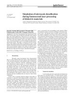
except the top surface, as shown in Fig. 1. The laser pulse is
focused onto the top surface with a diameter of
2 µm,andthe
laser irradiation is treated as a surface heat flux. The laser in-
tensity at the top surface is considered as having a Gaussian
distribution in both
x and y directions, which can be expressed
as:
I
s
(x, y, t) = I
0
(t) exp
−2
(x −x
0
)
2
+(y − y
0
)
2
r
2
, (1)
where
I
0
(t) is the time-dependent laser intensity at the center
of the laser pulse (
x = x
0
; y = y
0
)andr is the beam radius. The
temporal profile of the laser intensity is treated as increasing
linearly from zero to the maximum at
0.5psand then decreas-
ing to zero at the end of the pulse at
1ps. This is equivalent
to considering the laser pulse as
0.5ps FWHM. Practically,
many femtosecond lasers have shorter pulse width, of the
order of
100 fs. However, the time for energy to transfer from
electrons to the lattice is much longer. It was estimated to be
about
10 ps by measuring the damage threshold of fused sil-
ica as a function of laser pulse width [14]. Our calculations
show that, at a given fluence, this lattice heating time does not
change the peak temperature and the stress and strain as long
as it is less than
10 ps.
The local radiation intensity
I(x, y, t) within the target
is calculated considering exponential attenuation and surface
reflection as
I(x, y, t) = (1 − R
f
)I
s
(x, y, t), (2)
where
R
f
is the optical reflectivity. Properties of the fused
silica (Corning 7980) are used.
The thermal analysis is carried out for laser pulse en-
ergies of
0.2nJ, 0.25 nJ,and0.3nJ, respectively. Note that
FIGURE 1 Computational mesh (x : 10 µm, y : 10 µm, z : 3 µm)
this energy is the energy absorbed in a skin depth. In an ac-
tual process, the absorption of laser energy is low and the
depth of absorption is long; both depend on the laser inten-
sity. The maximum temperatures obtained are all lower than
the softening point of fused silica (
1858 K).
The transient temperature field obtained from the thermal
analysis is used as the thermal loading to solve the quasi-static
force equilibrium equations. The material is assumed to be
linearly elastic–perfectly plastic. The von Mises yield crite-
rion is used to model the onset of plasticity. The boundary
conditions are zero displacement in the bottom plane and no
displacement along the
z axis in the top surface, and all other
surfaces are stress-free. Details of the equations to be solved
have been described elsewhere [15].
Once the residual strain distribution is obtained, we can
compute the change of the index of refraction, since it is pro-
portional to the density as a first-order approximation. Kita-
mura et al. established a simple relationship to estimate the
change of the index of refraction resulting from densification
as [16]
∂n
n
= 0.4505
∂
, (3)
where n is the index of refraction of glass and δ/ is the den-
sification. The densification is related to the sum of the three
diagonal linear strains as
∂
=−
∂V
V
=−
∂u
∂x
+
∂v
∂y
+
∂w
∂z
. (4)
The non-linear finite-element solver, ABAQUS (HKS, Inc.,
Pawtucket, RI), is employed for the simulation. The mesh
used for the femtosecond pulsed laser simulation is shown
in Fig. 1. The Cartesian coordinate system is attached to the
computational domain, which has dimensions of
10 µm ×
10 µm ×3 µm. The elements have uniform size (0.2 µm)
along the
x and y directions and the size is stretched along
the
z direction. The total element number is 25 000.Mesh-
refinement tests are performed by increasing the mesh density
until calculations are independent of the mesh density. The
same mesh is used for both thermal and stress analyses.
Temperature-dependent properties are used, including
yield strength and Young’s modulus. However, the strain-
enhancement effect is neglected since data are not available.
3 Results and discussion
Temperature distributions along the x direction at
1ps are shown in Fig. 2. The laser pulse energy is 0.25 nJ
and the pulse center is located at x = y = 0 µm. The peak
temperature reaches a value of
T
max
= 1438 K at 1ps. It can
be estimated that the laser-heated region is around
1.6 µm
in radius on the top surface, slightly larger than the diam-
eter of the focused laser spot, which is
2 µm. We also cal-
culate the temperature distribution induced by laser pulses
with pulse widths of
100 fs, 10 ps,and1ns, respectively, using
the same laser energy. As shown in Fig. 3, the peak tempera-
tures induced by
100-fs and 10-ps pulses are about the same
as that by the
1-ps pulse. But, for the 1-ns pulse, the peak
temperature is only
986 K and is much lower than those ob-
tained from shorter pulses. This is because the heat-diffusion
ZHANG et al. Simulation of microscale densification during femtosecond laser processing of dielectric materials 947
FIGURE 2 Temperature profile along the x direction (laser pulse energy
0.25 nJ, pulse width 1 ps, laser spot size 2 µm)
1100
1000
900
800
FIGURE 3 Peak temperature induced by different laser pulse widths (laser
pulse energy 0.6 nJ, laser spot size 4 µm)
depth within a few ps is almost negligible. It is found that
temperature profiles of the
100-fs laser pulse are exactly the
same as those of the
1-ps laser pulse except that the peak
temperature is reached at
132 fs instead of 1ps.However,
as explained previously, even for a
100-fs femtosecond laser
pulse, it still takes picoseconds for energy to be coupled to
the lattice. With the same peak temperature, the laser-induced
strain and stress development is determined by the cooling
rate, which is the same in the two cases. Therefore, it is
not so critical to know exactly when the peak temperature is
obtained.
The distribution of the residual strain,
ε
xx
, on the surface
is shown in Fig. 4. It can be seen that the residual strain is
compressive with the maximum value at the core of the irra-
diated area. The compressive strain indicates densification of
the glass, and the area of compressive strain is smaller than
the laser spot size,
2 µm. The change of the index of refrac-
tion is calculated using (3) and (4), and is shown in Fig. 5.
Due to the symmetry of the model, only the change along the
x direction is plotted. Three different laser pulse energies are
used in the calculations. As shown in Fig. 5, the change of the
index of refraction increases with the pulse energy. The max-
imum value of
∆n is 0.5 ×10
−3
for the 0.3-nJ pulse, while it
FIGURE 4 Residual strain ε
xx
distribution (laser pulse energy 0.25 nJ,
pulse width 1 ps, laser focusing size 2 µm)
FIGURE 5 Change of index of refraction of fused silica irradiated by a sin-
gle ultra-fast laser pulse (laser pulse energy 0.2, 0.25, and 0.3 nJ, pulse width
1 ps, laser spot size 2 µm)
is only about 0.15 ×10
−3
for the 0.2-nJ pulse. The size of the
densified region where the index of refraction increases can
be estimated to be around
1 µm, which is one-half of the laser
spot size.
Figure 6 shows the diameters of the densification zone
in glass induced by different laser spot sizes but where the
peak temperature obtained during heating is kept the same.
It is found that the diameters of the strained regions are all
about one-half of the laser spot sizes. This small size is first
due to the negligible heat diffusion during the short period
of time. Further, the plastic strain is produced only in the
near-center region, since generation of plastic strain is highly
temperature dependent due to the temperature-dependent
stress–strain relation (similar to the narrowing of the ab-
sorption profile in a non-linear optical absorption process).
These two effects are responsible for the localized change
of the index of refraction as compared with the laser-heated
area.
948 Applied Physics A – Materials Science & Processing
FIGURE 6 Diameter of densification zone inside the fused glass induced
by different spot sizes but the same peak temperature (T
max
= 1438 K)
Lastly, it is noticed that the interaction between the fem-
tosecond laser pulse and the glass is a multi-photon process.
Considering the multi-photon effect, the region where the
laser pulse is absorbed as defined by the Gaussian distribu-
tion function is a factor of
√
n smaller than the laser beam
diameter, where
n is the number of photons involved in the ab-
sorption process. For most glasses, their band gaps are more
than twice the energy of the photons from a
Ti : sapphire laser
(
1.55 eV); therefore, a three or more photon absorption pro-
cess occurs. For a three-photon process, the absorption profile
is 1.73 times smaller than the laser spot. Or, in this calcu-
lation, the
2-µm-diameter region where the laser energy is
absorbed originates from a
3.46-µm-diameter laser spot. Our
computation results show that the change of the index of re-
fraction is confined in a region of
1 µm when the laser pulse
is absorbed in a
2-µm spot. This indicates that a 3.46-µm
laser beam can produce a change of index of refraction within
a
1-µm-diameter spot.
4 Summary
Femtosecond laser processing of fused silica is
simulated by using the finite-element method. Calculations
show that a localized change of index of refraction occurs
in an area smaller than the laser-heated region. The densifi-
cation zone is about one-half of the region where the laser
energy is absorbed. This densification zone is further re-
duced if the multi-photon absorption effect is considered.
Thus, we conclude that the laser-induced strain field, as well
as the multi-photon absorption effect, is responsible for the
localized change of the index of refraction of the glass.
ACKNOWLEDGEMENTS Support of this work by the National
Science Foundation (DMI-9908176) is gratefully acknowledged.
REFERENCES
1 E.N. Glezer, M. Milosavljevic, L. Huang, R.J. Finlay, T H. Her,
J.P. Callan, E. Mazur: Opt. Lett. 21, 2023 (1996)
2 K. Yamasaki, S. Juodkazis, M. Watanabe, H.B. Sun, S. Matsuo, H. Mi-
sawa: Appl. Phys. Lett. 76, 1000 (2000)
3 J.R. Qiu, K. Miura, K. Hirao: Jpn. J. Appl. Phys. Part 1 37, 2263 (1998)
4 K.M. Davis, K. Miura, N. Sugimoto, K. Hirao: Opt. Lett. 21, 1729
(1996)
5 K. Miura, J.R. Qiu, H. Inouye, T. Mitsuyu, K. Hirao: Appl. Phys. Lett.
71, 3329 (1997)
6 D. Homoelle, S. Wielandy, A.L. Gaeta, N.F. Borrelli, C. Smith: Opt.
Lett. 24, 1311 (1999)
7 C.B. Schaffer, A. Brodeur, J.F. Garcia, E. Mazur: Opt. Lett. 26, 93 (2001)
8 M. Will, S. Nolte, B.N. Chichkov, A. Tunnermann: Appl. Opt. 41, 4360
(2002)
9 A.M. Streltsov, N.F. Borrelli: J. Opt. Soc. Am. B 19, 2496 (2002)
10 C.B. Schaffer, J.F. Garcia, E. Mazur: Appl. Phys. A 76, 351 (2003)
11 N.F. Borrelli, C. Smith, D.C. Allan, T.P. Seward III: J. Opt. Soc. Am.
B 14, 1606 (1997)
12 T. Gorelik, M. Will, S. Nolte, A. Tuennermann, U. Glatzel: Appl. Phys.
A 76, 309 (2003)
13 B. Poumellec, L. Sudrie, M. Franco, B. Prade, A. Mysyrowicz: Opt.
Express 11, 1070 (2003)
14 B.C. Stuart, M.D. Feit, S. Herman, A.M. Rubenchik, B.W. Shore,
M.D. Perry: Phys. Rev. B 53, 1749 (1996)
15 G. Chen, X. Xu: J. Manuf. Sci. Eng. 123, 66 (2001)
16 N. Kitamura, Y. Toguchi, S. Funo, H. Yamashita, M. Kinoshita: J. Non-
Cryst. Solids 159, 241 (1993)