Điện tử số part 5
Bạn đang xem bản rút gọn của tài liệu. Xem và tải ngay bản đầy đủ của tài liệu tại đây (679.89 KB, 127 trang )
5/1
©
R.Lauwereins
Imec 2001
Digital
design
Combina-
torial
circuits
Sequential
circuits
FSMD
design
VHDL
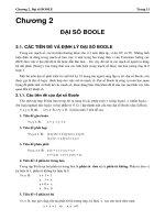
Course contents
•
Digital design
•
Combinatorial circuits: without status
•
Sequential circuits: with status
•
FSMD design: hardwired processors
Language based HW design: VHDL
5/2
©
R.Lauwereins
Imec 2001
Digital
design
Combina-
torial
circuits
Sequential
circuits
FSMD
design
VHDL
Language based HW design:
a VHDL primer
•
Introduction
•
A first look at VHDL
•
Signals and data types
•
VHDL operators
•
Concurrent versus sequential
statements
•
Sequential construction statements
•
Higher performance, less portability:
e.g. synthesis issues for Xilinx
5/3
©
R.Lauwereins
Imec 2001
Digital
design
Combina-
torial
circuits
Sequential
circuits
FSMD
design
VHDL
Language based HW design:
a VHDL primer
Introduction
•
A first look at VHDL
•
Signals and data types
•
VHDL operators
•
Concurrent versus sequential
statements
•
Sequential construction statements
•
Higher performance, less portability:
e.g. synthesis issues for Xilinx
5/4
©
R.Lauwereins
Imec 2001
Digital
design
Combina-
torial
circuits
Sequential
circuits
FSMD
design
VHDL
VHDL primer: Introduction
•
Acronym:
VHDL = VHSIC Hardware Description Language
VHSIC = Very High Speed Integrated Circuit
•
What is VHDL?
A programming language for describing the behavior
of digital systems
Design entry language, used for
Unambiguous specification at behavioral and RTL
level
Simulation (executable specification…)
Synthesis
Documentation
•
Standardisation: IEEE 1076
First version: 1986
Second version: 1993
New version about to appear
5/5
©
R.Lauwereins
Imec 2001
Digital
design
Combina-
torial
circuits
Sequential
circuits
FSMD
design
VHDL
VHDL primer: Introduction
•
When to use VHDL instead of
schematics?
Drawbacks:
VHDL is easy to learn but hard to master
(semantics are quite different from software
languages)
VHDL has a difficult syntax (Language sensitive
editors with templates for all language
constructs)
VHDL is very ‘wordy’: lots of code to type for just
a few simple things
A list of instructions is less intuitive to
understand than a block diagram for a human
being
VHDL is designed to make simulation efficient:
contains aspects that have hardly anything to do
with hardware behavior, but is useful to speed-up
event driven simulation
5/6
©
R.Lauwereins
Imec 2001
Digital
design
Combina-
torial
circuits
Sequential
circuits
FSMD
design
VHDL
VHDL primer: Introduction
•
When to use VHDL instead of
schematics?
Easier to capture complex circuits: higher level
of abstraction with automated synthesis
you specify ‘add’ instead of jotting
down a specific type of adder: the
synthesis tool will instantiate the
best type of adder under timing, area
& power constraints
easy to parametrise (e.g. word
length, queue depth)
easy to specify arrays of
components
Portable across many tools for simulation,
synthesis, analysis, verification, … of different
vendors (e.g. Synopsys, Mentor Graphics, …)
5/7
©
R.Lauwereins
Imec 2001
Digital
design
Combina-
torial
circuits
Sequential
circuits
FSMD
design
VHDL
VHDL primer: Introduction
•
Limitations of VHDL
The standard only describes syntax and
semantics, but not the coding style
you can specify the same behavior (e.g. MUX) in
an almost unlimited number of ways
each leading to a completely different
implementation (e.g. Multiplexor or tri-state bus)
which is synthesis tool dependent.
You should do lots of experimentation with style-
tool combinations to be able to predict how the
hardware will look like that will be synthesised. Is
prediction necessary? You also do not predict the
ASM generated by C; C is less efficient than ASM
but faster to write. Currently, it is hard to tolerate
the inefficiency caused by the higher level
specification for hardware.
Note: for DSP processors programmed in C, we do
predict ASM and have to experiment with style-
compiler combinations for efficiency reasons!!
5/8
©
R.Lauwereins
Imec 2001
Digital
design
Combina-
torial
circuits
Sequential
circuits
FSMD
design
VHDL
VHDL primer: Introduction
•
Limitations of VHDL (ctud)
Only a subset of VHDL can be automatically
synthesised; each vendor supports a different
subset
Only digital; special extension (not yet widely
adopted) for analog: VHDL-AMS (acronym for
VHDL Analog and Mixed Signal)
IEEE standard 1076.1-1999
is a super-set of the full IEEE VHDL
1076-1993 standard for digital design
5/9
©
R.Lauwereins
Imec 2001
Digital
design
Combina-
torial
circuits
Sequential
circuits
FSMD
design
VHDL
VHDL primer: Introduction
•
Abstraction levels
Behavioral
Interconnected functions
Only info on functions or algorithms
(what)
Only timing needed to let the
function work correctly
OK for VHDL
Behavioral synthesisers immature;
used for high level executable
specification in top-down design and
manual synthesis into RTL
5/10
©
R.Lauwereins
Imec 2001
Digital
design
Combina-
torial
circuits
Sequential
circuits
FSMD
design
VHDL
VHDL primer: Introduction
•
Abstraction levels
RTL
Interconnected registers and combinatorial units
Info on function (what) and architecture (how)
Cycle accurate
No technology dependent timing info
OK for VHDL
Good synthesisers
Gate level
Interconnected gates and flip-flops
Info on function and architecture
Info on technology dependent timing (gate delays)
Layout
Info on layout on silicon
Continuous timing
Analog effects
5/11
©
R.Lauwereins
Imec 2001
Digital
design
Combina-
torial
circuits
Sequential
circuits
FSMD
design
VHDL
VHDL primer: Introduction
•
Other hardware description languages
(HDL)
Verilog
More widespread in USA than in
Europe
Often required for gate level or RTL
level ASIC sign-off
Never ending discussion which is
better
PLD languages like ABEL, PALASM, …
These are more at the gate level,
capturing also technology dependent
features (e.g. detailed timing)
5/12
©
R.Lauwereins
Imec 2001
Digital
design
Combina-
torial
circuits
Sequential
circuits
FSMD
design
VHDL
VHDL primer: Introduction
•
Difference between HDLs and traditional
software programming languages
Concurrency: all hardware components operate
in parallel
Data types: support is needed for arbitrary size
integers, bit vectors, fixed point numbers
Concept of time
5/13
©
R.Lauwereins
Imec 2001
Digital
design
Combina-
torial
circuits
Sequential
circuits
FSMD
design
VHDL
Language based HW design:
a VHDL primer
•
Introduction
A first look at VHDL
•
Signals and data types
•
VHDL operators
•
Concurrent versus sequential
statements
•
Sequential construction statements
•
Higher performance, less portability:
e.g. synthesis issues for Xilinx
5/14
©
R.Lauwereins
Imec 2001
Digital
design
Combina-
torial
circuits
Sequential
circuits
FSMD
design
VHDL
A First look at VHDL:
Example 1 task description
•
Design a circuit named ‘Test’ with 3 8-bit
inputs (In1, In2, In3) and two boolean
outputs (Out1, Out2). The first output
equals ‘1’ when the first and second input
are equal; the second output equals ‘1’
when the first and third input are equal.
•
Let’s first make a schematic design:
5/15
©
R.Lauwereins
Imec 2001
Digital
design
Combina-
torial
circuits
Sequential
circuits
FSMD
design
VHDL
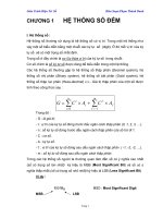
A First look at VHDL:
Schematic specification
•
The circuit will be hierarchically
decomposed into a top level component
‘Test’ containing 2 instantiations of a
comparator component ‘Compare’
In1
In2
In3
Test
Out1
Out2
Compare
A
B
EQ
Compare
A
B
EQ
5/16
©
R.Lauwereins
Imec 2001
Digital
design
Combina-
torial
circuits
Sequential
circuits
FSMD
design
VHDL
A
B
EQ
Compare
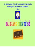
A First look at VHDL:
Schematic specification
•
The comparator is then hierarchically
decomposed into a gate level
combinatorial circuit
A[0]
B[0]
A[1]
B[1]
A[7]
B[7]
EQ
XNOR
AND
5/17
©
R.Lauwereins
Imec 2001
Digital
design
Combina-
torial
circuits
Sequential
circuits
FSMD
design
VHDL
A First look at VHDL:
Entity and Architecture
•
Declaration of the ‘Compare’ design
entity:
Eight bit comparator
entity Compare is
port( A,B: in bit_vector(0 to 7);
EQ: out bit);
end entity Compare;
architecture Behav1 of Compare is
begin
EQ <= ‘1’ when (A=B) else ‘0’;
end architecture Behav1;
‘Entity’ specifies
the interface
to the circuit, the
black box of a
schematic
Input and output
signals are called
‘ports’
‘Architecture’ describes
the behavior and structure
of the entity,
the internals of the box
Notes:
- Multiple architectures per entity are possible: different ways
of implementing same behavior
- This architecture specifies behavior at RTL level and not
the actual structure of gates; synthesis tool will automatically
translate this RTL behavioral description into gate level
- Ports have an explicit direction and are (vectors of) bits
5/18
©
R.Lauwereins
Imec 2001
Digital
design
Combina-
torial
circuits
Sequential
circuits
FSMD
design
VHDL
A First look at VHDL:
Component and Instantiation
•
Specification of the next higher level in
the circuit hierarchy: ‘Test’
Dual comparator Test component
entity Test is
port( In1,In2,In3: in bit_vector(0 to 7);
Out1,Out2: out bit);
end entity Test;
architecture Struct1 of Test is
component Comparator is
port( X,Y: in bit_vector(0 to 7);
Z: out bit);
end component Comparator;
begin
Compare1: component Comparator port map (In1,In2,Out1);
Compare2: component Comparator port map (In1,In3,Out2);
end architecture Struct1;
Two instantiations
of the same component
‘Comparator’ with its
signal binding
Notes:
- The two ‘comparator’ components work concurrently!!!
- This architecture describes structure, i.e. how this entity
consists of an interconnection of lower level components
Virtual device: allows
for concurrent
development of both
hierarchical levels,
by different persons.
‘Comparator’ will be
bound to ‘Compare’
later
5/19
©
R.Lauwereins
Imec 2001
Digital
design
Combina-
torial
circuits
Sequential
circuits
FSMD
design
VHDL
A First look at VHDL:
Comparison with C
•
This is very similar to software
programming languages, e.g. C
/* Eight bit comparator
*/
int Compare
(int A, int B)
{
return (A == B);
}
Interface to the function
Behavior of the function
Notes:
- Only one behavior per function possible
- Behavior is specified at rather high level and will be
automatically translated by the compiler into ASM instructions
- Function arguments do not have a direction and are of type int
Inputs and outputs are
called ‘arguments’
5/20
©
R.Lauwereins
Imec 2001
Digital
design
Combina-
torial
circuits
Sequential
circuits
FSMD
design
VHDL
A First look at VHDL:
Comparison with C
•
This is how the higher hierarchical level
looks like in C
/* Dual comparator Test program
*/
main()
{
int In1, In2, In3;
int Out1, Out2;
Out1 = Compare(In1, In2);
Out2 = Compare(In1, In3);
}
Two calls to the function
‘Compare’ with its
argument binding
Notes:
- The two ‘compare’ function calls are executed sequentially
- This main program is executed once and stops. In VHDL, all
components describe relations that are valid continuously and
forever
5/21
©
R.Lauwereins
Imec 2001
Digital
design
Combina-
torial
circuits
Sequential
circuits
FSMD
design
VHDL
A First look at VHDL:
Configuration
•
When an entity has multiple
architectures, how do you indicate which
one to use?
•
How do you bind ‘Components’ to
‘Entities’?
Configuration information: architecture selection
and component-entity binding
configuration Build1 of Test is
for Struct1
for Compare1: Comparator use entity Compare(Behav1)
port map (A => X, B => Y, EQ => Z);
end for;
for others: Comparator use entity Compare(Behav1)
port map (A => X, B => Y, EQ => Z);
end for;
end for;
end configuration Build1;
Note: ‘configuration’ corresponds in SW to ‘linking’
Both ‘use entity’s could
be combined in one:
for All: Comparator
5/22
©
R.Lauwereins
Imec 2001
Digital
design
Combina-
torial
circuits
Sequential
circuits
FSMD
design
VHDL
A First look at VHDL:
Syntax
ENTITY:
entity Entity_name is
port( Signal_name: in Signal_type;
Signal_name: out Signal_type);
end entity Entity_name;
ARCHITECTURE:
architecture Architecture_name of Entity_name is
local_signal_declarations;
component_declarations;
begin
statements;
end architecture Architecture_name;
5/23
©
R.Lauwereins
Imec 2001
Digital
design
Combina-
torial
circuits
Sequential
circuits
FSMD
design
VHDL
A First look at VHDL:
Syntax
COMPONENT:
component Component_name is
port( Signal_name: in Signal_type;
Signal_name: out Signal_type);
end component Component_name;
COMPONENT INSTANTIATION:
component instantiation
Instance_name: component Component_name
port map (Signal_list);
or
direct instantiation
Instance_name: entity Entity_name(Architecture_name)
port map (Signal_list);
SIGNAL LIST:
two variants:
variant 1: ordered list of signals as in software languages
e.g. (In1,In2,Out1)
variant 2: named list
e.g. (B => In2, EQ => Out1, A => In1)
Locally used name
Name used in
component declaration
5/24
©
R.Lauwereins
Imec 2001
Digital
design
Combina-
torial
circuits
Sequential
circuits
FSMD
design
VHDL
A First look at VHDL:
Syntax
CONFIGURATION:
configuration Config_name of Entity_name is
for Architecture_name
for Instance_name: Component_name use entity
Entity_name(Architecture_name)
port map (Signal_list);
end for;
end for;
end configuration Config_name;
5/25
©
R.Lauwereins
Imec 2001
Digital
design
Combina-
torial
circuits
Sequential
circuits
FSMD
design
VHDL
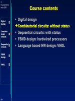
A First look at VHDL:
Example 2
•
Declare a 3-input AND gate
A
B
C
Y
3-input AND gate
entity AND3 is
port ( A,B,C: in bit;
Y: out bit);
end entity AND3;
architecture RTL of AND3 is
begin
Y <= ‘1’ when ((A=‘1’) and (B=‘1’) and (C=‘1’)) else ‘0’;
end architecture RTL;