rf power control ho parameters
Bạn đang xem bản rút gọn của tài liệu. Xem và tải ngay bản đầy đủ của tài liệu tại đây (484.75 KB, 155 trang )
RF Power Control and Handover
Algorithm
dn9814129
Issue 12-0 en
# Nokia Corporation
Nokia Proprietary and Confidential
1 (155)
2003219
S10.5 ETSI documentation set
The information in this document is subject to change without notice and describes only the
product defined in the introduction of this documentation. This document is intended for the use
of Nokia's customers only for the purposes of the agreement under which the document is
submitted, and no part of it may be reproduced or transmitted in any form or means without the
prior written permission of Nokia. The document has been prepared to be used by professional
and properly trained personnel, and the customer assumes full responsibility when using it.
Nokia welcomes customer comments as part of the process of continuous development and
improvement of the documentation.
The information or statements given in this document concerning the suitability, capacity, or
performance of the mentioned hardware or software products cannot be considered binding but
shall be defined in the agreement made between Nokia and the customer. However, Nokia has
made all reasonable efforts to ensure that the instructions contained in the document are
adequate and free of material errors and omissions. Nokia will, if necessary, explain issues
which may not be covered by the document.
Nokia's liability for any errors in the document is limited to the documentary correction of errors.
NOKIA WILL NOT BE RESPONSIBLE IN ANY EVENT FOR ERRORS IN THIS DOCUMENT
OR FOR ANY DAMAGES, INCIDENTAL OR CONSEQUENTIAL (INCLUDING MONETARY
LOSSES), that might arise from the use of this document or the information in it.
This document and the product it describes are considered protected by copyright according to
the applicable laws.
NOKIA logo is a registered trademark of Nokia Corporation.
Other product names mentioned in this document may be trademarks of their respective
companies, and they are mentioned for identification purposes only.
Copyright © Nokia Corporation 2002. All rights reserved.
2 (155) # Nokia Corporation
Nokia Proprietary and Confidential
dn9814129
Issue 12-0 en
RF Power Control and Handover Algorithm
Contents
Contents 3
List of tables 5
List of figures 6
Summary of changes 7
1 Overview to RF Power Control and Handover Algorithm 11
2 RF power control and handovers in BSC 15
3 RF Power Control and Handover Algorithm: radio link measurement
processing in BTS and BSC 19
4 RF Power Control and Handover Algorithm: averaging of MSBS
distance 27
5 Bookkeeping and averaging of the RXLEV of the adjacent cell 29
6 RF Power Control and Handover Algorithm: MS speed averaging 33
7 RF Power Control and Handover Algorithm: variable averaging
window size 37
8 RF Power Control and Handover Algorithm: averaging of rapidly
changing signal level 39
9 RF Power Control and Handover Algorithm: FER 41
10 RF Power Control 47
10.1 RF Power Control and Handover Algorithm: threshold comparison and
command 47
10.2 RF Power Control and Handover Algorithm: MS power increase due to
signal level 49
10.3 RF Power Control and Handover Algorithm: MS power decrease due to
signal level 51
10.4 RF Power Control and Handover Algorithm: MS power increase due to
signal quality 52
10.5 RF Power Control and Handover Algorithm: MS power decrease due to
signal quality 56
10.6 RF Power Control and Handover Algorithm: BTS power increase due to
signal level 61
10.7 RF Power Control and Handover Algorithm: BTS power decrease due to
signal level 63
10.8 RF Power Control and Handover Algorithm: BTS power increase due to
signal quality 65
10.9 RF Power Control and Handover Algorithm: BTS power decrease due to
dn9814129
Issue 12-0 en
# Nokia Corporation
Nokia Proprietary and Confidential
3 (155)
Contents
signal quality 69
11 RF Power Control and Handover Algorithm: BSC handovers 75
11.1 RF Power Control and Handover Algorithm: handover due to uplink/
downlink interference 76
11.2 RF Power Control and Handover Algorithm: handover due to uplink/
downlink quality 79
11.3 RF Power Control and Handover Algorithm: handover due to uplink/
downlink level 82
11.4 RF Power Control and Handover Algorithm: target cell evaluation
according to radio criteria 84
11.5 RF Power Control and Handover Algorithm: handover due to MS-BS
distance 86
11.6 RF Power Control and Handover Algorithm: handover due to rapid field
drop 91
11.7 RF Power Control and Handover Algorithm: handover due to fast/slow-
moving MS 93
11.8 RF Power Control and Handover Algorithm: power budget handover 100
11.9 RF Power Control and Handover Algorithm: umbrella handover 103
11.10 RF Power Control and Handover Algorithm: handover due to turn-around-
corner MS 108
11.11 RF Power Control and Handover Algorithm: traffic reason handover 112
11.12 RF Power Control and Handover Algorithm: forced handover 113
11.13 RF Power Control and Handover Algorithm: BSC Initiated Traffic Reason
Handover 114
11.13.1 BSC Initiated Traffic Reason Handover with GSM-WCDMA Inter-System
Handover 117
11.14 RF Power Control and Handover Algorithm: Directed Retry Procedure 117
11.15 RF Power Control and Handover Algorithm: order of preference of target
cells 120
11.16 RF Power Control and Handover Algorithm: interval between handovers
and handover attempts 121
11.17 RF Power Control and Handover Algorithm: channel allocation criteria
based on the minimum acceptable C/N ratio 124
11.18 RF Power Control and Handover Algorithm: optimisation of the MS power
level in handover and in call set-up 128
12 RF Power Control and Handover Algorithm parameters 133
4 (155) # Nokia Corporation
Nokia Proprietary and Confidential
dn9814129
Issue 12-0 en
RF Power Control and Handover Algorithm
List of tables
dn9814129
Issue 12-0 en
# Nokia Corporation
Nokia Proprietary and Confidential
5 (155)
List of tables
List of figures
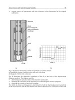
Figure 1. Implementation of Power Control and Handover 11
Figure 2. Example of correlation table of one codec, hopping or non-hopping 42
Figure 3. Example of calculated FEP values of one codec derived from the
correlation table, hopping or non-hopping 42
Figure 4. Correction values for updating the correlation table 43
Figure 5. Inversed correction values for using the correlation table 45
Figure 6. MS power increase due to signal level 49
Figure 7. MS power decrease due to signal level 51
Figure 8. MS power increase due to signal quality 53
Figure 9. MS power decrease due to signal quality 57
Figure 10. BTS power increase due to signal level 61
Figure 11. BTS power decrease due to signal level 64
Figure 12. BTS power increase due to signal quality 66
Figure 13. BTS power decrease due to signal quality 70
Figure 14. Handover due to uplink/downlink interference 77
Figure 15. Handover due to uplink/downlink quality 80
Figure 16. Handover due the uplink/downlink level 83
Figure 17. Handover due to MS-BS distance 87
Figure 18. Handover due to rapid field drop 92
Figure 19. Handover due to fast/slow-moving MS 95
Figure 20. Power budget handover 101
Figure 21. Umbrella handover 104
Figure 22. Handover due to turn-around-corner MS 109
Figure 23. Traffic reason handover 112
Figure 24. BSC Initiated Traffic Reason Handover 115
Figure 25. Directed Retry Procedure 118
6 (155) # Nokia Corporation
Nokia Proprietary and Confidential
dn9814129
Issue 12-0 en
RF Power Control and Handover Algorithm
Summary of changes
Summary of changes
Changes between document issues are cumulative. Therefore, the latest document
issue contains all changes made to previous issues.
Changes made between issues 11 and 10
The document has been revised throughout to comply with the latest
documentation standards.
Chapter Processing of radio link measurements
Section FER added.
Chapter RF Power control, section PC threshold comparison and PC
command
The mention of maximum MS transmission power parameters updated and GSM
850 information added.
Chapter RF Power control, section MS power increase due to signal quality
Note of AMR PC Rx Quality thresholds added in subsection
Threshold
comparison
.
Chapter RF Power control, section MS power decrease due to signal quality
Note of AMR PC Rx Quality thresholds added in subsection
Threshold
comparison
.
Chapter RF Power control, section BTS power increase due to signal quality
Note of AMR PC Rx Quality thresholds added in subsection
Threshold
comparison
.
Chapter RF Power control, section BTS power decrease due to signal
quality
Note of AMR PC Rx Quality thresholds added in subsection
Threshold
comparison
.
Chapter Handover and Chapter Parameters, section Figures
Equations of Pa, PBGT(n), MAX_INTF_LEV, MS_TXPWR_OPT, pwr(n) and
their explanations updated. Also GSM 850 information added.
dn9814129
Issue 12-0 en
# Nokia Corporation
Nokia Proprietary and Confidential
7 (155)
Summary of changes
Chapter Handover, section Handover due to uplink/downlink interference
In subsection Threshold comparison, uplink quality corrected to downlink quality
in the mention of handover cause downlink interference.
Chapter Handover, section Handover due to uplink/downlink quality
Note of new AMR HO Rx Quality thresholds added in subsection
Threshold
comparison
.
Chapter Handover, section Handover due to fast/slow-moving MS
In figure
Handover due to fast/slow-moving MS
the equation
FastMovingThreshold(n)=0 corrected to FastMovingThreshold(n)>0.
Chapter Handover, section BSC initiated traffic reason handover
Note of parameter
TrhoGuardTime
applying added.
Chapter Handover, section Optimisation of the MS power level in handover
and in call set-up
The mention of maximum MS transmission power parameters updated and GSM
850 information added.
Chapter Parameters
Parameter
AmhTrafficControlMCN
added.
GSM 850 information added to parameters
gsmMacrocellThreshold
,
gsmMicrocellThreshold
and
MsTxPwrMin
.
New parameters
AmrHandoverFr.ThresholdDLRXQual
,
AmrHandoverFr.
ThresholdULRXQual
,
AmrHandoverHr.ThresholdDLRXQual
,
AmrHandoverHr.ThresholdULRXQual
,
AmrPowerControlFr.
PcLowerThresholdDLRxQual
,
AmrPowerControlFr.
PcLowerThresholdULRxQual
,
AmrPowerControlFr.
PcUpperThresholdDLRxQual
,
AmrPowerControlFr.
PcUpperThresholdULRxQual
,
AmrPowerControlHr.
PcLowerThresholdDLRxQual
,
AmrPowerControlHr.
PcLowerThresholdULRxQual
,
AmrPowerControlHr.
PcUpperThresholdDLRxQual
and
AmrPowerControlHr.
PcUpperThresholdULRxQual
added.
Parameter
MsTxPwrMax
changed to parameters
MsTxPwrMaxGSM
(BTS) and
MsTxPwrMaxGSM1x00
(BTS). Parameter
MsTxPwrMaxCell
changed to
parameters
MsTxPwrMaxGSM
(ADJ) and
MsTxPwrMaxGSM1x00
(ADJ).
Also GSM 850 information added.
8 (155) # Nokia Corporation
Nokia Proprietary and Confidential
dn9814129
Issue 12-0 en
RF Power Control and Handover Algorithm
Chapter Parameters, section Figures
In figure
Handover due to fast/slow-moving MS
the equation
FastMovingThreshold(n)=0 corrected to FastMovingThreshold(n)>0.
Changes made between issues 10 and 9
Chapter RF power control, section BTS power decrease due to signal level
Description of variable downlink power step size added. Figure
BTS power
decrease due to signal level
and its caption updated.
Chapter RF power control, section BTS power decrease due to signal level
In section Threshold comparison the sentence The BTS power is always
decreased by fixed step removed due to the addition of the description of
variable downlink power step size.
Chapter RF power control, section BTS power decrease due to signal
quality
Description of variable downlink power step size added to figure
BTS power
decrease due to signal quality.
Chapter RF power control, section BTS power decrease due to signal
quality
In section Threshold comparison the sentence The BTS power is always
decreased by fixed step removed.
Chapter RF power control, section BTS power decrese due to signal quality
Description of variable downlink power step size added to its own subsection
Power change step size.
Chapter Handover, section Handover due to fast/slow moving MS
Description of the definition of the maximum power capability of the MS
corrected in subsection
Target cell evaluation
.
Chapter Handover, section Umbrella handover
Figure
Umbrella handover
modified.
Chapter Handover, section BSC initiated traffic reason handover
Figure
BSC initiated traffic reason handover
updated.
dn9814129
Issue 12-0 en
# Nokia Corporation
Nokia Proprietary and Confidential
9 (155)
Summary of changes
Description of the use of parameter
Cause Field in Handover Request Supported
corrected.
Chapter Parameters
New parameters
OptimumRxLevDL
and
VariableDLStepUse
added.
Changes made between issues 9 and 8
Chapter Handover, section BSC initiated traffic reason handover
A new section.
Chapter Parameters
New parameters:
AmhMaxLoadOfTgtCell, AmhTrhoPbgtMargin,
AmhUpperLoadThreshold, TrhoGuardTime, UpperLimitCellLoadHSCSD
.
10 (155) # Nokia Corporation
Nokia Proprietary and Confidential
dn9814129
Issue 12-0 en
RF Power Control and Handover Algorithm
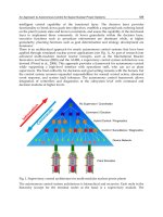
1 Overview to RF Power Control and
Handover Algorithm
The Radio Frequency (RF) Power Control and Handover Algorithm is
responsible for processing radio link measurements and for the threshold
comparison and decision of Power Control (PC) and Handover (HO). The
following figure shows how the different functions involved in the preparation
and decision of Power Control and Handover are physically implemented.
Figure 1. Implementation of Power Control and Handover
The Base Station Controller (BSC) supports plain measurement preprocessing in
the Base Transceiver Station (BTS); the BTS can calculate an average from two,
three or the maximum of four measurement results and send the averaged results
to the BSC in the same form as the raw measurement results. The purpose of the
preprocessing in the BTS is to cut down the load of the LAPD-link when
necessary by reducing the number of measurement results that the BTS sends to
the BSC.
B S C
M S / B T S
M S C
- measurement
averaging
- HO threshold
comparison
- HO target cell
evaluation
- HO decision
& command
- PC threshold
comparison
- PC command
Radio
link
measurements
external HO:
- decision
& command
dn9814129
Issue 12-0 en
# Nokia Corporation
Nokia Proprietary and Confidential
11 (155)
Overview to RF Power Control and Handover Algorithm
The BSC executes the final processing of the measurement samples:
bookkeeping of the last received samples and averaging procedure. After the
averaging procedure the BSC performs both the PC threshold comparison and the
HO threshold comparison. The BSC determines the Radio Frequency (RF) output
power of the Mobile Station (MS) and the BTS by comparing the processed
measurement results with the PC thresholds. If the HO threshold comparison
indicates that a handover might be required, the BSC examines the potential
target cells for the handover. The BSC performs intra-BSC handovers
autonomously. If there is an inter-BSC handover to be performed, the BSC sends
a list of the preferred cells to the MSC and the MSC performs the handover
according to the list.
The software of the BSC is divided into program blocks according to different
functions. The main functions of the handover and power control are divided into
two program blocks. One is responsible for the actual performance of the
handover, and the other for processing the radio link measurements, the threshold
comparison and the decision algorithms of the handover and power control.
The required parameters are stored in the BSS Radio Network Configuration
Database. All parameters controlling the handover and power control are
administered either on a cell-by-cell basis or on a transceiver-by-transceiver basis
by O & M; that is, by using the local MMI in the BSC site or the Nokia NetAct.
By changing the values of the parameters it is possible to affect the RF power
control and handover decisions at all stages of the procedure, that is during
measurement preprocessing, threshold comparison, and the decision algorithm.
Related topics
RF power control and handovers in BSC
Radio link measurement processing in BTS and BSC
Averaging of MS-BS distance
Bookkeeping and averaging of the RXLEV of the adjacent cell
MS speed averaging
Variable averaging window size
Averaging of rapidly changing signal level
FER
RF power control
12 (155) # Nokia Corporation
Nokia Proprietary and Confidential
dn9814129
Issue 12-0 en
RF Power Control and Handover Algorithm
BSC handovers
Parameters
dn9814129
Issue 12-0 en
# Nokia Corporation
Nokia Proprietary and Confidential
13 (155)
Overview to RF Power Control and Handover Algorithm
14 (155) # Nokia Corporation
Nokia Proprietary and Confidential
dn9814129
Issue 12-0 en
RF Power Control and Handover Algorithm
2 RF power control and handovers in BSC
The Radio Frequency (RF) power control strategy employed by the BSC defines
the RF power command that is signalled to the MS, and the RF power level that is
used by the BTS. The RF power control optimises the RF output power of the MS
and the BTS and simultaneously ensures that the signal level required at the BTS/
MS is sufficient to maintain adequate speech/data quality.
The RF power level to be employed in each case is based on the measurement
results reported by the MS /BTS and on the various parameters set for each cell.
BSC handovers
The handover decisions made by the BSC are based on the measurement results
reported by the MS/BTS and on the various parameters set for each cell.
A handover is normally caused by radio criteria but the handover algorithm
present is also able to perform handovers caused by six other reasons:
.
The radio network recovery management initiates a forced handover (intra-
cell or inter-cell) in order to empty a cell or a TRX (see Radio Network
Recovery and State Management ).
.
The radio resource management initiates a forced inter-cell handover in
order to make room for a high priority call in situations of congestion, that
is, Pre-emption Procedure (see Radio Resource Pre-emption and Queueing
in BSC ).
.
Due to congestion in the call set-up phase, a handover from a Stand Alone
Dedicated Control Channel (SDCCH) of the serving cell to a Traffic
Channel (TCH) of an adjacent cell, that is, Directed Retry Procedure (see
Directed Retry Procedure in BSC ).
.
The MSC requests the BSC to perform a specified number of handovers
from one specified cell to other specified cells, that is, Traffic Reason
Handover (see Traffic Reason Handover Procedure in BSC ).
dn9814129
Issue 12-0 en
# Nokia Corporation
Nokia Proprietary and Confidential
15 (155)
RF power control and handovers in BSC
.
A handover from an extended range cell to an inner cell and vice versa
when the site type is Nokia 2nd generation (see Extended Cell ), or when
the site type is Nokia Talk-family, a handover between normal and
extended coverage areas within an extended range cell (see Extended Cell
Range ).
.
BSC internal traffic control (for example, a handover from an umbrella cell
to a microcell).
The BSC uses different handover decision algorithms for handovers caused by
normal radio criteria and handovers caused by other reasons than radio criteria.
When an MS moves from one cell coverage area to another, the radio link
measurements show low signal level (RXLEV) and/or quality (RXQUAL) on the
current serving cell and a better RXLEV available from a neighbouring cell, or
the neighbouring cell allows communication with a lower RF power level. The
crucial principle for the BSC selecting the target cells for the handover caused by
radio criteria is that the neighbouring cell must be better than the current serving
cell in order for the handover to be useful.
If other reasons than radio criteria cause the handover, it is not necessary for the
target cell to be better than the serving cell. It suffices that the target cell serves
the call well enough; for example, a handover from an umbrella cell to a
microcell is performed whenever the call can be maintained on the neighbouring
microcell.
Target cell evaluation
The evaluation on the preferred list of the target cells is based on:
1. radio link measurements
2. priority levels of the neighbouring cells
3. load of the neighbouring cells which belong to the local BSS
First the BSC defines and selects those cells which meet the requirements for the
radio link properties. Then it ranks the cells according to the priority levels and
the load of the neighbouring cells, with the exceptions of the forced handover
procedure, the directed retry procedure and the traffic reason handover procedure
when the BSC ranks the cells only according to radio link properties.
Handover types
The possible types of handover are the following:
16 (155) # Nokia Corporation
Nokia Proprietary and Confidential
dn9814129
Issue 12-0 en
RF Power Control and Handover Algorithm
.
intra-BTS handover (interference problems)
.
intra-BSC handover
.
inter-BSC handover (that is, MSC performs the handover)
The handover may take place during a call from a TCH to a TCH (see Handover
Signalling in BSC ). An intra-BTS handover can take place either to a radio time
slot on a new carrier or to a different time slot on the same carrier.
A handover may also take place from an SDCCH to a stand alone dedicated
control channel during the initial signalling period of call set-up (see Handover
Signalling in BSC ). The parameter EnableSdcchHO indicates whether the
handover from SDCCH to SDCCH is enabled. As far as the algorithm is
concerned, the handover from SDCCH to SDCCH does not differ from the
handover from a TCH to a TCH. However, umbrella handover is not performed
from SDCCH to SDCCH.
During the call setup phase in situations of congestion (see Directed Retry
Procedure in BSC ) a handover can take place from the SDCCH of the serving
cell to a traffic channel of an adjacent cell (the parameter EnableSdcchHO has
no effect on the directed retry procedure).
The handover is synchronised or non-synchronised, depending on whether the
cells are synchronised or not. This information is administered on an adjacent
cell-by-cell basis by means of the O & M with the parameter Synchronised ,
which indicates whether the adjacent cell is synchronised with the serving cell.
The value 'yes' indicates that the cells are synchronised.
Interdependence of handover and power control
The Power Control (PC), for both the BTS and the MS, runs independently in
parallel with the handover (HO). With a proper choice of the PC and HO
thresholds, the BSC maintains call quality by means of power control and
proposes handover only when the MS actually reaches the border of the serving
cell. If both the HO and PC threshold conditions are fulfilled, the handover has
greater priority than the power control. If the handover cannot be performed at
that very moment, power increase may be used as first aid.
The BSC determines which RF power level the MS that has been handed over
will use as the initial RF power in the target cell. The default initial RF power
level is the maximum RF power that an MS is permitted to use on a traffic
channel in the target cell. However, in the case of an intra-BSC handover, the PC/
HO algorithm is also able to optimise the initial RF power level so that the RF
power level is lower if the radio link properties of the target cell are good.
Optimisation of the MS power level in a handover cuts down the probability of
dn9814129
Issue 12-0 en
# Nokia Corporation
Nokia Proprietary and Confidential
17 (155)
RF power control and handovers in BSC
high RF power peaks in the uplink after HOs. This way it reduces the uplink
interference in the radio network. This property is controlled by the parameters
MsPwrOptLevel(n) (inter-cell handover) and the parameter
OptimumRxLevUL (intra-cell handover).
Note
Optimisation of the MS power level in a handover is an optional feature.
Back to Overview to RF Power Control and Handover Algorithm.
18 (155) # Nokia Corporation
Nokia Proprietary and Confidential
dn9814129
Issue 12-0 en
RF Power Control and Handover Algorithm
3 RF Power Control and Handover
Algorithm: radio link measurement
processing in BTS and BSC
Measurement preprocessing in BTS
The measurement preprocessing in the BTS comprises of plain averaging of the
following measurement results:
.
uplink signal level
.
uplink signal quality
.
downlink signal level (serving cell)
.
downlink signal quality
.
MS-BS distance
.
MS speed
.
signal level of the adjacent cells
The averaging procedure is controlled by the parameter BTSMeasAver . The
parameter indicates whether the BTS can calculate the average over 1, 2, 3 or 4
SACCH multiframes (value 1 actually means that the BTS will not perform
averaging). The parameter is controlled on a cell-by-cell basis.
When averaging is not active in the BTS, the BTS sends the raw measurement
results it has received from the MS (downlink) and the results of its own
measurements (uplink) to the BSC in every SACCH multiframe period. If
averaging is used in the BTS, the BSC does not receive measurement results from
the BTS in every SACCH multiframe period, but the BTS sends the averaged
results in every second, third or fourth SACCH multiframe period. The BTS
sends the averaged results to the BSC in the same form as the raw measurement
results. The BSC executes the final averaging of the measurement samples.
dn9814129
Issue 12-0 en
# Nokia Corporation
Nokia Proprietary and Confidential
19 (155)
RF Power Control and Handover Algorithm: radio link measurement processing in BTS
and BSC
Note
When the other averaging parameters are being selected, the factor to be taken
into consideration is whether averaging will be performed already in the BTS,
otherwise it is possible that the averaging window sizes accidentally become
much longer than expected.
Weighted averaging of quality and level
The following measurement results are averaged according to the weighted
averaging technique to produce a reliable quality and level estimate:
.
uplink signal level
.
uplink signal quality
.
downlink signal level (serving cell)
.
downlink signal quality
The measurement results are averaged separately for both handover and power
control.
The weighting takes the reliability of each measurement sample into
consideration in the averaging procedure. The reliability of the measurement
samples varies in consequence of discontinuous transmission (DTX).
Power control and handover parameters for weighted averaging
The averaging procedure is controlled by parameters. Power control and
handover have averaging parameters of their own. The BSC uses separate
parameters for quality and level measurements as well as for uplink and downlink
measurements. All averaging parameters are administered on a cell-by-cell basis
by Nokia NetAct. The averaging parameters are the following:
1. PcAveragingLevDL is used for calculating averaged values from
downlink signal level measurements for PC threshold comparison.
2. PcAveragingLevUL is used for calculating averaged values from
uplink signal level measurements for PC threshold comparison.
3. PcAveragingQualDL is used for calculating averaged values from
downlink signal quality measurements for PC threshold comparison.
4. PcAveragingQualUL is used for calculating averaged values from
uplink signal quality measurements for PC threshold comparison.
20 (155) # Nokia Corporation
Nokia Proprietary and Confidential
dn9814129
Issue 12-0 en
RF Power Control and Handover Algorithm
5. HoAveragingLevDL is used for calculating averaged values from
downlink signal level measurements for HO threshold comparison.
6. HoAveragingLevUL is used for calculating averaged values from
uplink signal level measurements for HO threshold comparison.
7. HoAveragingQualDL is used for calculating averaged values from
downlink signal quality measurements for HO threshold comparison.
8. HoAveragingQualUL is used for calculating averaged values from
uplink signal quality measurements for HO threshold comparison.
Each averaging parameter is composed of two parts: the size of the averaging
window (Window size ) and the weighting factor (Weighting ). The range of
the averaging window size is from 1 to 32 SACCH multiframe periods, where the
value 1 means that there is basically no averaging at all. The range of the
weighting factor is from 1 to 3. These values are the same for all the parameters
listed above.
Averaging methods for quality and level
The BSC calculates new averaged values in every SACCH multiframe period (if
preprocessing is used in the BTS, in every second, third or fourth SACCH
multiframe, in other words whenever the BSC receives measurement results from
the BTS). The averaging procedure is able to take into account the maximum of
32 most recent measurement samples.
The basic averaging procedure does not start until the required number of
measurement samples is available. After the averaging procedure has started, the
BSC calculates a new averaged value from the most recent measurement samples
in every SACCH multiframe period (sliding window technique).
For example, if the value of the parameter PcAveragingLevUL/Window
size is 8, the averaging of uplink level for power control can start as soon as
the BSC has received 8 measurement results.
Fast averaging method
The BSC is also able to start the averaging of level and quality from the first
measurement sample. In this case the BSC calculates averaged values from those
measurement samples which are available until the number of measurement
samples is adequate to calculate averaged values over the intervals determined by
the parameters (Window size ). For example, if the value of the parameter
PcAveragingLevUL/Window size is 8 but the number of available
measurement samples is 5, the BSC calculates the average from those 5 available
measurement samples. This property is known as the fast averaging method and it
is controlled by the following parameters:
dn9814129
Issue 12-0 en
# Nokia Corporation
Nokia Proprietary and Confidential
21 (155)
RF Power Control and Handover Algorithm: radio link measurement processing in BTS
and BSC
1. EnaFastAveCallSetup parameter indicates whether the fast
averaging method is enabled at the beginning of a SDCCH seizure (either
in a call or in a SDCCH handover). The fast averaging method is enabled
when the value is 'yes'.
2. EnaFastAveHO parameter indicates whether the fast averaging method
is enabled at the beginning of a TCH seizure (either in a call or in a
handover). The fast averaging method is enabled when the value is 'yes'.
3. EnaFastAvePC parameter indicates whether the fast averaging of signal
quality measurements and the scaling of signal level measurements are
enabled just after the increase/decrease of the MS/BTS transmission power.
The fast averaging method and the scaling of measurement results are
enabled when the value is 'yes'.
The advantage of the fast averaging method is that handover and power control
threshold comparisons can start as soon as the BSC has received the first
measurement sample. The fast averaging method does not, however, effect in any
way the threshold comparison. The BSC performs the threshold comparison in
the same way whether the fast averaging method is used or not. The parameters
listed above need to be on when using the fast averaging method, if not then the
BSC functions as normally. However, they do not all have to be on at the same
time, because each parameter affects a different stage.
Note
The fast averaging method concerns only the measurement results of the serving
cell not the measurement results of the adjacent cell (see Bookkeeping and
averaging of the RXLEV of the adjacent cell ).
Weighted averaging method
Besides the measurement results, the MS/BTS indicates to the BSC whether
Discontinuous Transmission (DTX) was used during the previous SACCH
multiframe period (uplink/downlink). DTX NOT USED indicates that the MS/
BTS has transmitted all TDMA frames during the previous SACCH multiframe
period. DTX USED indicates that the MS/BTS did not transmit all TDMA frames
during the previous SACCH multiframe period. For speech communication DTX
is randomly distributed over the SACCH multiframe periods. If the DTX value
cannot be determined, the BSC assumes that DTX was used.
If the MS/BTS did not transmit all TDMA frames, the reliability of quality and
level estimation is not as good as it would be if all TDMA frames were
transmitted. Because of this, during the averaging procedure, the samples
accessed over all TDMA frames are given more weight than the samples accessed
over a subset of TDMA frames. For example, when uplink signal quality for the
22 (155) # Nokia Corporation
Nokia Proprietary and Confidential
dn9814129
Issue 12-0 en
RF Power Control and Handover Algorithm
PC is being averaged, the weighting factor has the value of the parameter
PcAveragingQualUL/Weighting (range from 1 to 3) if DTX was not
used, whereas the weighting factor is 1 for the measurement results when DTX
was used.
The corresponding weighted averaging technique which takes into account
whether the MS/BTS has used Discontinous Transmission (DTX) during the
previous SACCH multiframe period is described below by averaging the uplink
signal level for the PC.
DTX is not allowed on the SDCCH.
Examples
The example below indicates the averaging procedure where the samples
available include indication on either DTX not used (0) or DTX used (1). In the
example, the parameters (PcAveragingLevUL ) are Weighting , which has
the value 2, and Window size , which has the value 8.
>time
sample: 1 2 3 4 5 6 7 8
DTX used: 0 1 0 0 1 1 1 0
uplink
level: 35 42 33 36 39 40 3 9 35
(2*35)+ (1*42)+ + (2*35)
AV_RXLEV_UL_PC = = 36
2+1+2+2+1+1+1+2
The example below indicates the averaging procedure where the samples
available include indication on either DTX not used (0) or DTX used (1). In the
example, the parameters (PcAveragingQualUL) are Weighting , which
has the value 2, and Window size , which has the value 6.
>time
sample: 1 2 3 4 5 6
DTX used: 0 1 0 0 1 1
uplink
quality: 0 4 0 0 2 1
BER: 0.14% 2.26% 0.14% 0.14% 0.57% 0.28%
(2*0.14)+ (1*2.26)+ + (1*0.28)
AV_RXQUAL_UL_PC = = 0.43%
2+1+2+2+1+1
dn9814129
Issue 12-0 en
# Nokia Corporation
Nokia Proprietary and Confidential
23 (155)
RF Power Control and Handover Algorithm: radio link measurement processing in BTS
and BSC
Note that the BSC uses Bit Error Rate (BER) values defined for each quality band
when it averages the signal quality measurements (this also concerns threshold
comparison) (see
GSM Recommendation 05.08
).
Averaged results of quality and level
The following correspondence is found between the measurement results,
averaging parameters and the averaged results. These averaged results are used in
the equations for handover and power control threshold comparison.
AV_RXLEV_DL_PC
AV_RXLEV_UL_PC
AV_RXQUAL_DL_PC
AV_RXQUAL_UL_PC
AV_RXLEV_DL_HO
AV_RXLEV_UL_HO
AV_RXQUAL_DL_HO
AV_RXQUAL_UL_HO
MEASUREMENT
RESULT
AVERAGING
PARAMETERS
AVERAGED
RESULT
downlink
level
uplink
level
downlink
quality
uplink
quality
downlink
level
uplink
level
downlink
quality
uplink
quality
PcAveragingLevDL
- Window size
- Weighting
PcAveragingLevUL
- Window size
- Weighting
PcAveragingQualDL
- Window size
- Weighting
PcAveragingQualUL
- Window size
- Weighting
HoAveragingLevDL
- Window size
- Weighting
HoAveragingLevUL
- Window size
- Weighting
HoAveragingQualDL
- Window size
- Weighting
HoAveragingQualUL
- Window size
- Weighting
24 (155) # Nokia Corporation
Nokia Proprietary and Confidential
dn9814129
Issue 12-0 en
RF Power Control and Handover Algorithm
Case of a missing downlink measurement report
If, for any multiframe, the downlink measurement report which is normally
received from the MS is missing or the report includes an indication that
downlink measurement results are not valid, the basic procedure is that the BSC
executes merely the processing for the uplink measurement results (uplink signal
level and uplink signal quality) and both the PC threshold comparison and the
HO threshold comparison for these averages.
In this case no new averaged values are calculated from downlink measurements.
As a result, no threshold comparison based on those particular averages is started
(for example BTS power control). Similarly, the bookkeeping of the downlink
measurement results is frozen.
As long as downlink measurement reports are missing (or they are not valid), the
BSC is only able to control the power of the MS and perform handovers (intra-
cell or inter-cell) whose cause is either uplink quality or uplink interference.
Normal actions will be resumed when the next valid downlink measurement
report arrives.
If the optional feature "Chained cells in rapid field drop" is employed, the BSC is
also able to perform an imperative handover caused by a rapid field drop to an
adjacent cell, despite the missing (or non-valid) downlink measurement report.
The principle and the function of the feature "Chained cells in rapid field drop"
will be explained in detail in RF Power Control and Handover Algorithm: BSC
handovers .
Initialisation of the old measurement results
The measurement results (uplink or downlink) preceding an MS/BTS power
change are not valid after the power change. If the scaling of measurement results
is disabled (selected with the parameter EnaFastAvePC ), the averaging and
threshold comparison based on those measurement results (uplink/downlink)
must start from the beginning after the power change (this concerns both
handover and power control). In this case the BSC initialises the measurement
results preceding the power change as follows:
1. MS power increase/decrease:
.
The BSC initialises uplink measurement results.
2. BTS power increase/decrease:
.
The BSC initialises downlink measurement results (serving cell).
dn9814129
Issue 12-0 en
# Nokia Corporation
Nokia Proprietary and Confidential
25 (155)
RF Power Control and Handover Algorithm: radio link measurement processing in BTS
and BSC